
Abstract
An analysis of fiber mechanics during cutting is conducted using a rotating cutting set up. It was found that high cutting speeds, low cutting angles, and high cutting normal forces lead to low values of cutting force. In this study, a set of high performance organic and inorganic fiber types are tested throughout different conditions of cut testing. Inorganic fibers gave the lowest specific cutting force. Values of cutting stresses on the edge of the blade were proved to be a function of fibers’ Young’s moduli. Higher Young’s moduli give lower cutting stresses on the blade edge while cutting fibers. Organic fibers were found to have a higher cutting resistance than carbon and glass fibers. A significant indirect correlation was found between the shear stress of the fibers and the fiber Young’s modulus. The value of the cutting force is significantly affected by both normal force and cutting velocity. The analysis of fiber mechanics during cutting is conducted using a rotating cutting set-up. It was found that high cutting speeds, low cutting angles, and high cutting normal forces lead to low values of cutting force. In this study, a set of high performance organic and inorganic fiber types are tested throughout different conditions of cut testing. Inorganic fibers gave the lowest specific cutting force. Values of cutting stresses on the edge of the blade were proved to be a function of fibers Young’s modulus. Higher Young’s modulus gives lower cutting stresses on the blade edge while cutting fibers. Organic fibers were found to have a higher cutting resistance than carbon and glass fibers. A significant indirect correlation was found between the shear stress of the fibers and the fibers Young’s modulus. The value of the cutting force is significantly affected by the normal force, cutting angle, and cutting velocity.
Introduction
In the last decades of the twentieth century, a new generation of synthetic fibers (HPF) has been modified with high tenacity and high modulus of elasticity, which opened a wide field of applications with superior technical requirements, such as protection fabric, stab and bullet-prove armors, tire cords, and ropes. Also, the HPF polymer composites (HPPC) found use in high-end automobile components, bicycle frames, belts, protective cases, fishing rods, and more recently in Aeronautics and Aerospace industries, Oil and Gas industry, Unmanned aerial vehicles, Satellite, and Wind turbine blades [1,2]. Polymer fibers have now reached tenacities over 3.5 N/tex and Young’s modulus over 150 N/tex. The carbon fiber was introduced with a high modulus and tenacity over 5 GPa and up to 800 GPa [3], respectively. In all cases, these materials may be knitted, woven, or braided to form the final required product, and thereafter be cut into suitable sizes. In some products such as gloves, stab, and bullet resistance armors, the fabrics are subjected to cutting forces [3–5]. High-performance fibers (HPF) can be used for innovative diversified high tech applications because of their high strength and temperature stability. They replace the traditional use of metals in places where the weight is to be reduced. Other areas will evolve because of the ever-growing stringent requirements of energy saving in transportation. Thus, these fibers have the potential to participate in the solutions of high tech products of today and tomorrow [6]. The HPPC being non-homogeneous, anisotropic, and reinforced by fiber is difficult to cut or machine. Nevertheless, it is essential to increase the cutting efficiency of composite laminates with the least damages. Many recent studies have focused on the relationship between process parameters and cutting quality [7,8]. The HPF shows different behavior of failure fraction morphology and depends on the balance of internal bonding [9]. Under the tensile load, several types of fractional cracks occur due to the deference of internal bonding [10]. Various shapes of the fractural morphology of the fiber failure were classified: brittle, ductile, axial splits, and granular, according to each type of fiber. Due to their high strength-to-weight ratio, high damping ability, low density, carbon fiber-reinforced polymer (CFRP) composites are used widely in many areas, such as aerospace, automobile, and energy industry [11]. The protection against cuts and punctures requires deep investigation of HPF cutting resistance at the actual working conditions. In some cases, the best protection is achieved when high-performance fibers are combined with stainless steel or glass fibers [12]. The high-performance fibers have found increasing attention in the application in several industrial composites, tires, conveyers, transition belts, and mechanical transitions parts, bullet helmets, hard protection panels, different vehicle parts, and aircraft reinforcement parts. Therefore, several methods and standards to measure the cutting force of filament, yarns, or fabric have been introduced [3,13–17]. Each method gives a different evaluation of the material results. However, few investigations have been done on the cutting resistance of textile materials. Kevlar and Vectran fibers, generally, demonstrate excellent cut resistance, although this can depend upon the test used [18]. Early tests measured the load necessary for a 5 cm diameter blade to begin cutting a tensioned knitted fabric, which indicates the high cut resistance [13]. The measured cutting force for protective clothing is used to provide knowledge about cut, tear, and puncture fabric resistance. The cutting force distribution profile is determined by the sharpness of a blade. It can be observed from the experimental results that the cutting force is proportional to the contact length between the blade and the material [3]. The design of the robotic-controlled razor blade required the knowledge of the normal load value and the cutting speed suitable for each type of fabric according to its aerial density to perform a clear cut of the fabric [19]. In some applications, it is required to chop continuous filament into pieces, hence it possesses better processability due to its good process compatibility with the traditional manufacturing processes, such as injection molding and extrusion compounding [20]. A large amount of work remains to be done to fully integrate all the components to understand how the cut mechanism and testing can evolve to be better predictive tools [15]. In this work, a new principle for measuring the cutting force was introduced to facilitate the measurement of all parameters affecting the cutting force value, especially important the cutting speed and the cutting angle. The new cut set-up has been developed to measure the cut resistance of some of the high-performance filament yarns, including Kevlar 29, Kevlar 129, Vectran, Carbon fiber, Glass-S fiber, and Polyester. On the developed cutting set-up, the cutting force and the effective parameters were experimentally analyzed as a function of filament yarn material.
Materials and methods
Materials
Fiber properties
The multifilament yarn properties such as linear density, tensile modulus, strain to failure, and tensile strength are measured. Table 1 shows the tested fiber types. All the filament yarns characterized in this study were multifilament.
Fiber properties.
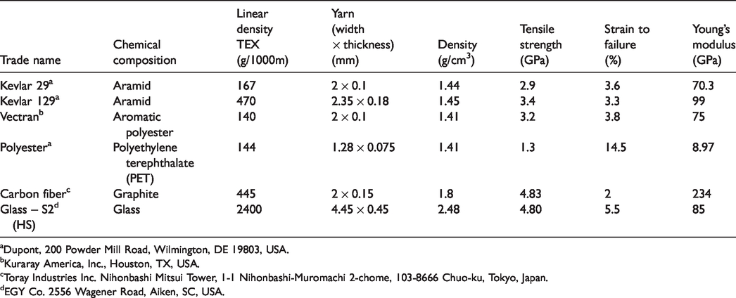
aDupont, 200 Powder Mill Road, Wilmington, DE 19803, USA.
bKuraray America, Inc., Houston, TX, USA.
cToray Industries Inc. Nihonbashi Mitsui Tower, 1-1 Nihonbashi-Muromachi 2-chome, 103-8666 Chuo-ku, Tokyo, Japan.
dEGY Co. 2556 Wagener Road, Aiken, SC, USA.
Basic design set-up
A prototype of the test apparatus was developed [22] to satisfy the requirements for measuring the cutting resistance of the fabric as well as the cutting resistance of the fibers and filament yarns. Figure 1 illustrates the main elements of the set-up.
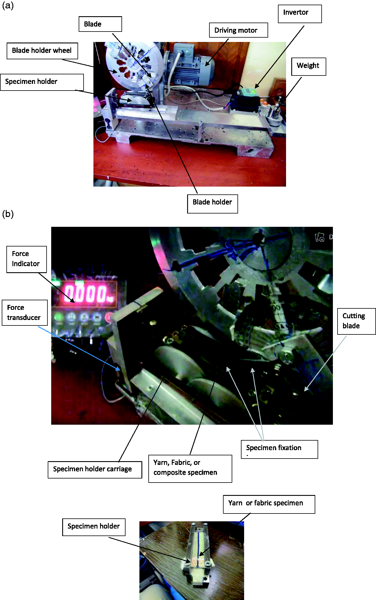
Cutting resistance set-up: (a) cutting set-up; (b) sample holder.
The sample of the filament yarn is clamped in the specimen holder. The holder itself is fixed on the holder carriage which can slide freely on one end of the lever. While the other end of the lever under a dead weight presses the sample to the blade path only during the cutting process. The blade is fixed on the blade holder wheel at the adjusted cutting angle. The rotation of the blade holder wheel will direct the blade edge against the fixed specimen in carriage pushing its end against the load cell to measure the value of the cutting force. The value of the load will be displayed on the force indicator. The signal will be instantaneously fed to DA system and recorded on an excel file as a time function.
Figure 1(b) shows the fixture for gripping a fiber, filament yarn, or fabric specimen on opposing sides of the sample holder. To mount a specimen for cut testing, one end was clamped in the test fixture, and then the fabric was pre-tensioned to 5cN using a static weight on the other side. The rpm of the blade holder was adjusted through the variable speed motor that can attain a cutting speed up to 250 mm/s. The blade cutting angle can be adjusted between 0° – 90°. The average maximum cutting force (CFmax) “N”, the cutting energy (CE) “J”, and their coefficient of variation CV% were calculated for each specimen as well. A new blade cutting edge was used for each experiment to minimize blade dulling effects.
Measuring shear stress of the filament yarns
To determine the shear stress of the different fibers, a special attachment was manufactured to fix the fibers firmly with a notch of a width of one mm. Tensile strength tester Multitest 5-xt was used to perform a cutting through the cross-section of the filament yarn. The attachment with the sample was mounted in the place of the lower jaw of the tester. Cutting was performed by a fixed blade mounted in the upper jaw at the speed of 100 mm/s.
Figure 2 shows the testing arrangement for measuring the sheer force of the filament yarns. Five specimens were tested for each type of filament yarns.

Filament yarn shear testing attachment.
Results and discussions
Analysis of the mechanism of cutting on the setup
The cutting during any mechanical action with a sharp blade is usually combined cutting with tension and flexing of the sample while the blade is passing through the material. The designed set-up successfully simulates this situation. Figure 3 shows the mechanism of sample cutting by the blade fixed on the rotating wheel.

Analysis of the mechanism of cutting.
The analysis of the cutting process videos for the filament yarns or fabric on the set-up, illustrated in Figure 3, shows that the material was deformed during the cutting in both x-y and y-z planes, and the contact point of material slides over the blade edge. This model simulates the cutting in the case of stabbing or slashing the material which depends on the blade cutting angle, blade sharpness, coefficient of friction, fiber material, the value of normal force on the sample, cutting angle, and cutting speed [3,4,20,21,23]. While the sheer force of the material depends on the molecular structure, the mechanical properties of the cut sample, tensile property, Young’s modulus, as well as the cutting angle.
Analysis of the continuous filament yarns cutting resistance
Several types of filament yarns were tested on the set-up to study the effect of the normal force and cutting velocity on their cutting resistance force. Figure 4 shows the cutting force versus displacement of various types of high-performance filament yarns at a normal load of 760 cN. In all cases, in Figure 4, cutting force showed a gradual increase in the intensity with the displacement of the blade through the filament yarn, followed by a rapid drop in the cutting force accompanying the failure of most filaments. Since the filament yarns have different counts, the specific cutting resistance force was calculated and illustrated in Figure 5. The highest values of the specific cutting force were given by Kevlar 29 and Vectran filament yarns while the inorganic fibers, carbon and glass, gave the lowest specific cutting force, despite the high modulus, the high strength, and the fair strain of carbon fibers at failure. It was noticed that there is a distinct difference in fracture characteristics in the different organic types of fibers.
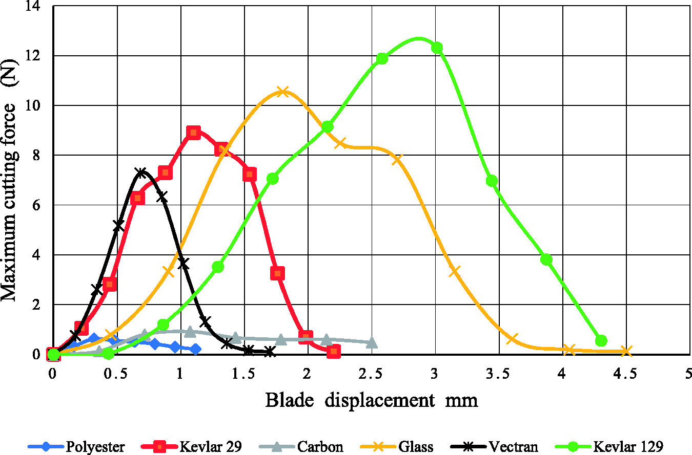
Cutting resistance force versus displacement of the different fibers.

Specific cutting resistance force versus displacement of the different fibers.
Mechanism of cutting
The mechanism of cutting starts with pushing the filaments at the point of contact of the material with the blade while increasing the force. When the normal stress exceeds the material shear stress at the point of contact, the blade starts to make a micro-crack on the surface of the filament. The cutting mechanism on the set-up indicates that the filaments will also be subjected to tensile stress and flexing stress, and the failure will take place under the effect of these three stresses [22]. The required total cutting force is equal to the force needed to reach the value of the material’s failure equivalent stress. Thus, the material starts being cut at the indentation point causing a micro-crack. The filament will then continue to partially fail under the shear stress, tensile stress, and flexing stress. According to the molecular structure, the failure will occur at the point with the lowest value of the material stress. In the case of the inorganic high modulus fibers, once the blade starts to provide microcrack on the surface of the fibers, the tensile and flexural stresses increase, leading to a quick fracture [23].
To verify the above statement, the SEM of carbon and Kevlar 29 multifilament filament yarns were performed under the following conditions: pure cutting and cutting on the cutting set- up the unit. The SEM of the carbon fibers and Kevlar fibers are given in Figures 6 and 7, which illustrates that the cutting on the set-up is a combination of cutting tension and flexural failure. The pure cutting by the blade is shown in Figure 6(a) and (b) for carbon fiber, and Figure 7(a) and (b) for Kevlar fiber. The SEM of the fibers cut on the set-up is given in Figure 6(c) and (d) and Figure 7(c) and (d). The morphology of the failure of the fiber cut in the case of the pure cut is smooth and particulate while the cut on the set-up is smooth cut, particulate, and of granular morphology due to the effect of the tensile and flexural stresses [23]. For carbon fibers, the stress concentration, which depends on the depth of the crack, causes a crack to grow over the blade fiber contact region, and hence the crack is initiated. The break of carbon fiber under the tensile stress shows the granular form reflecting the void structure [24] as shown in Figure 6(d). Carbon fibers will break when even a low curvature is applied during the testing, therefore reducing its cutting force [24]. This is why carbon fibers have lower specific cutting forces.

SEM micrographs of the pure cut, cutting, tensile, and flexural fracture of carbon fibers: (b) carbon filament yarn; pure cutting failure; (c) cutting under tension; (d) cutting under tension.
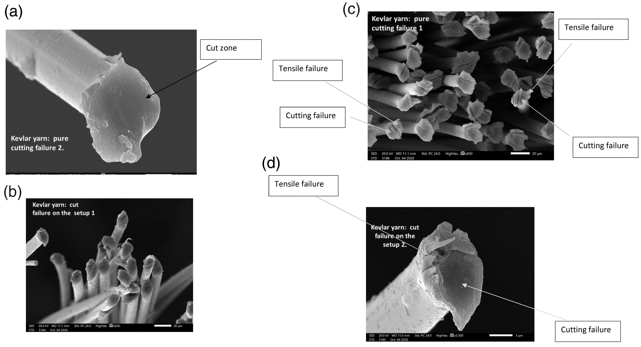
SEM micrographs of the pure cut, cutting, tensile and flexural fracture of Kevlar fibers: (a, b) pure cutting; (c, d) cutting under tension.
In the case of Kevlar filament yarn, the failure is quite different from that of the carbon fiber, as illustrated in Figure 7(a) to (d). Different shapes are found according to the stress applied. Branching of the crack leads the ends with the fibrillated break in a single or multiple split [25]. In the case of cutting under the tensile strength, the fibrils will retain back after the failure, as shown in Figure 7(c) and (d), and the fibrillated break is noticed.
The transverse cross-section of carbon and Kevlar fibers (Figure 7), in the case of pure cutting and after cutting on the set-up, proves the soundness of the above analysis of the cutting mechanism. The value of the specific cutting stress was found to be different, as illustrated in Figure 8(a), and the specific cutting stress value of the Kevlar fibers was the highest compared to the carbon and glass fibers, while the polyester filament yarns gave the lowest specific cutting stress. The cutting angle has a great influence on the value of the specific force as indicated in Figure 8(b), generally, as the cutting angle increases the measured cutting force decreases, for all measured types of fiber. This is because the failure of the yarns is due to cutting stress, and no tensile or flexing stresses are participating in the failure of the specimen.

Specific cutting force of tested fibers: (a) specific cutting force for different types of fibers; (b) specific cutting force vs cutting angle for Kevlar fibers.
The values of cutting stress of the different filament yarns are given in Figure 9, which indicates that the Polyester fibers need higher cutting stress than the glass and carbon fibers.
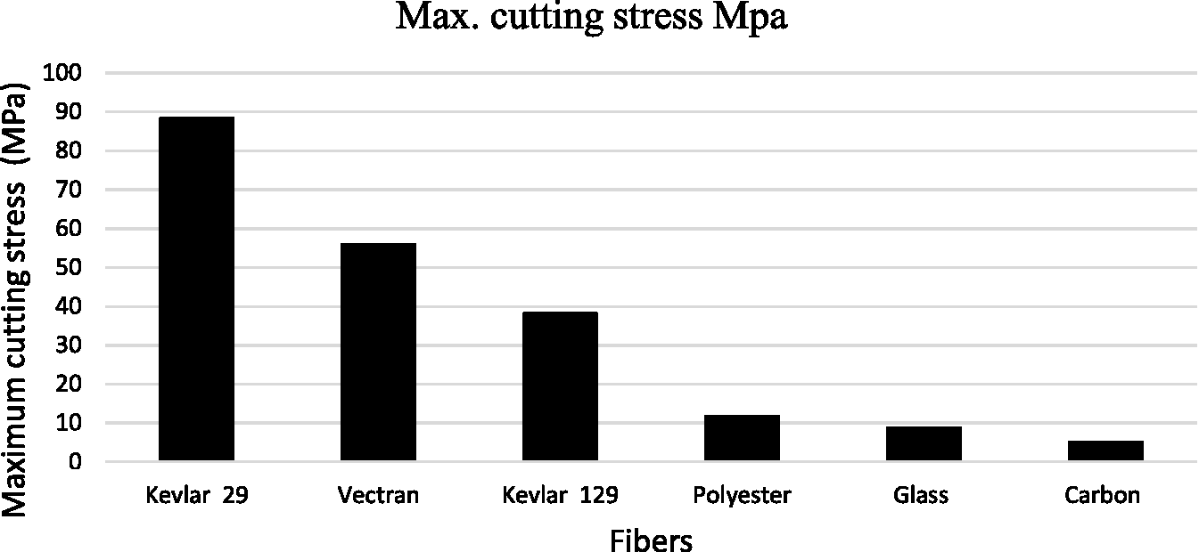
Maximum cutting stress for different types of fibers.
For the organic fibers, the microcrack starts under the high value of indentation stress. The tensile stress and flexural stress play a lower effect on the value of the cutting resistance force of the material [11]. Figure 10 illustrates that the stress needed causes failure of the filament yarn under the cutting stress caused by the blade edge for Kevlar 29 filament yarns has the highest value. Higher stress must be applied to cause its failure.
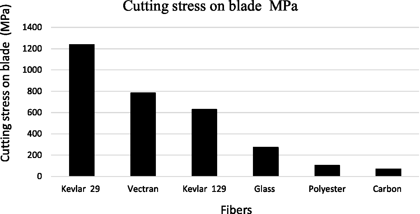
Cutting stress acting on the blade edge for different types of fibers.
Figure 11 indicates the existence of a direct correlation between the cutting stress on the blade edge and the maximum cutting stress on the filament yarns. The coefficient of correlation is 0.99.

Cutting stress on the blade edge versus the maximum cutting stress on the filament yarns.
The material’s stiffness is directly proportional to its Young’s modulus, consequently, the possibility of formation and spreading of microcrack under the low indentation stress increases as the Young’s modulus increases. The above results indicate that there is a relation between the filament yarn cutting stress and the blade edge stress and the filament yarn Young’s modulus, as shown in Figure 12.

Filament yarn cutting stress versus Young’s modulus: (a) blade cutting stress; (b) filament yarn cutting stress.
The specific cutting energy is expected to be higher for Kevlar 29 and lower for carbon, glass, and polyester filament yarns, due to their early failure due to the propagation of the microcracks (Figure 13). The specific cutting energy was found to be inversely proportional to the material’s Young’s modulus, and hence the material stiffness is directly proportional to their Young’s modulus.

Specific cutting energy: (a) for different fibers; (b) versus Young’s modulus.
The difference in the cutting resistance of the fibers may be directly related to the molecular structure, which characterized the orientation of the chains and bonding of the polymer molecules. They may be very highly oriented, as in the case of Kevlar and Vectran, compared to the Polyester fibers. For example, Kevlar fiber has a tensile strength due to the presence of the hydrogen bond between the chains. These hydrogen bonds are tying the polymer molecules together which results in increasing the tensile strength. Vectran, spun from Vectran liquid crystal polymer (LCP) which is highly oriented, has an excellent tensile strength similar to Kevlar. Carbon fibers exhibit substantially better strength and stiffness values. However, carbon fiber is very sensitive to flexural stress. The glass fiber is a rigid and brittle material because the molecules are locked into place with a little wiggle room, consequently, the micro-crack will propagate at a higher speed than the cutting speed and a lower value of cutting force was recorded. This will explain the difference between the fiber cutting force and cutting energy results illustrated in Figures 8 to 13.
Fiber shear stress
The shear force was measured on the set-up, illustrated in Figure 2, using the same traveling speed of the cutting blade 100 mm/s. Figure 14 indicated that Kevlar 29 fibers have the highest value of the shear stress while the glass fibers have the lowest value.

Shear stress of different fibers.
Comparing the values of the cutting stress and the shear stress for the different fibers, Figures 9 and 14 show that in all cases the shear stress of fiber is higher than its maximum cutting stress. This proves that failure is not purely shear of the full fiber cross-section, as explained by the SEM photos (Figure 7), and the percentage of the components of the total stress plays a decisive role in the determination of the fiber cutting mechanism. A high correlation factor was found between the shear stress of the fibers and the fiber Young’s modulus, R = −0.95.
Effect of the normal force
The increase of the normal load on the filament yarn affects the value of the cutting force. This is because it will increase the initial pressure on the filament at the point of contact with the edge of the cutting blade. Consequently, it will speed up the formation of the micro-crack at the point of the contact and accelerate the shear failure of the material, especially for an inorganic fiber as shown in Figure 15. Depending on the strength-fraction toughness relation of the material, both the crack-initiation and crack-growth toughness will increase [26].

Maximum cutting force versus normal load: (a) carbon filament yarn; (b) Kevlar filament yarn.
Effect of cutting velocity
The blade moves at a certain cutting velocity, consequently, the energy of cutting the yarn will be higher as the cutting velocity increases, this probably increases the shear stress at the point of yarn - blade contact. It also, that speeds up the mechanism of failure at a low value of cutting force.
Experimentally it was found that the cutting force decreases significantly [27] as the cutting speed increases, as illustrated in Figure 16. In the case of the inorganic filament yarns, carbon, the rate of the decrease of the cutting force is highly affected by the cutting velocity than in the case of the organic fibers, Kevlar 29.

Maximum cutting force versus cutting velocity for carbon filament yarn and Kevlar filament yarn.
Conclusion
The cut resistance of the high-performance filament yarns under tension-shear loading conditions was measured using a newly developed rotating set-up. The cutting force-blade displacement relation and the energy required to cut through the yarn were determined for the filament yarns, Kevlar 29, Kevlar 129, Vectran, Carbon, Glass, Polyester, as well as their shear stress. From this study, the following can be summarized: The resistance of the high-performance filament yarn to cutting in tension-shear can be consistently measured on the designed rotary cutting set-up. The cutting resistance of the filament yarn is inversely proportional to the square of its Young’s modulus. The stress on the blade edge is much higher than the yarns cutting stress and inversely proportional to their Young’s modulus. The specific cut energy is inversely proportional to the fibers Young’s modulus. The cutting resistance depends on the material toughness to initiate the micro-crack in the material at the blade edge. SEM examination of the fiber cross-section indicates that the failure mechanisms of the filament happened under the cutting, flexing, and tension stresses. The cutting force of the filament yarn is affected significantly by the normal load and cutting speed.
Creating an appropriate model for the calculation of forces is necessary to completely understand the behavior of the high-performance fibers under different cutting conditions.
Footnotes
Declaration of conflicting interests
The author(s) declared no potential conflicts of interest with respect to the research, authorship, and/or publication of this article.
Funding
The author(s) received no financial support for the research, authorship, and/or publication of this article.