
Abstract
Different from the other design parameters in general drogues, there are few studies about the parameter of Length-Width Ratio (LWR). Therefore, the fluid structure coupling model based on the Finite Element Method was used to study the deceleration characteristics and terminal trajectory stability of parachute system in this work. And the graphic transformation technology commonly used in Computer Graphics was used to realize the following of flow field with the trajectory movement. In this work, the cruciform parachutes with different LWR were taken as the research objects, and the above method was used to obtain the trajectory curves, deceleration characteristic curves, and stability curves of the cruciform parachutes under different external conditions. It was found that the deceleration performance was negatively correlated with the LWR when the other design parameters and working conditions remained unchanged, and the trajectory stability and the stability of the parachute were positively correlated with the LWR. Subsequently, the cruciform parachute with the LWR of 4.5 was used for airdropping test, and the accuracy of numerical method used in this work was verified. Then the deceleration processes of cruciform parachute (LWR: 4.5) under different dropping conditions were calculated. It could be found that the external launching conditions had a limited impact on the deceleration performance. The LWR was another design parameter that had a greater impact on the deceleration performance after the parameter of canopy area. Finally, the drag coefficient correction equation representing the deceleration performance was proposed for the first time.
Keywords
Introduction
As a typical fabric product, parachute has the characteristics of light weight, easy folding, and low cost. It has an irreplaceable position in the fields of aviation, aerospace, and weapons. In the field of weapons, parachutes are not only used to decelerate the aerial bombs, to ensure that the aerial bombs have a certain amount of loitering time, but also used to control the terminal trajectory of the aerial bombs to ensure the damage effect of the aerial bombs. At present, there are more than 10 types of parachutes existed, but not all of them could be used for weapons, such as circle parachutes and square parachutes. On the one hand, the common types have a larger oscillation angle (circle parachutes: ± 10°– ± 40°, square parachutes: ± 20°1,2), which has a significant influence on the terminal trajectory of parachute. On the other hand, the common types have a larger drag coefficient (circle parachutes: 0.75–0.8, square parachutes: 0.8–11,2), which leads to long time hanging and cannot meet the demand for attack timeliness. The other types, such as parafoils, are too complicated in structure and too large in compression volume. They cannot be installed on aerial bombs at all. Therefore, the parachutes used for aerial bombs mainly include cone parachutes, wave-ring parachutes, guide surface parachutes, high damping rotary parachutes, cruciform parachutes, etc. However, the first three types have longer cords, larger opening dynamic load coefficient, and the weight of the whole parachute system is almost 1.5 times than that of the latter two types. 1 As for some small separated aerial bombs which are used for special purposes, such as sub-munitions, the first three types are almost impossible to install. Meanwhile, the high damping rotating parachutes have the characteristics of high processing cost, so the cruciform parachutes are widely used in the deceleration and control of terminal trajectory of small separated aerial bombs.
In addition to the parachute design parameters such as nominal area, cords length, and fabric porosity, the unique design parameter LWR of the cruciform parachute also has a very important impact on the stability, attitude and contact angle of the aerial bombs. However, in the field of parachute design and research, only general design parameters such as nominal area, cords length and fabric porosity are studied at present. While, the existing parachute design manuals only make a qualitative conclusion on LWR, that is, LWR has an impact on the stability of the cruciform parachute opening.1,2 What’s more, the more important effect of LWR on deceleration performance and stability of terminal trajectory are rarely reported. Currently, the research methods to study the influence of design parameters on parachute performance mainly include test and numerical simulation. The test method can be further subdivided into wind tunnel test, airdrop test, and ground drag test. However, the test method has a long cycle and requires a lot of manpower and financial resources. Due to the limitation of test conditions and data collection technologies, test results have strong randomness and contingency, and it is difficult to obtain the law of influence from the test results. Contrarily, with the development of computer hardware and the increasing maturity of algorithms, numerical methods are increasingly used in parachute design. The numerical model can be roughly divided into multi-body dynamics model and discrete model. The multi-body dynamics model regards the parachute-payload system as a rigid body, and it is relatively simple to deal with the external wind field, and cannot consider the influence of external conditions on the deceleration characteristics during the parachute opening. Therefore, it is mainly used for the terminal trajectory analysis of the parachute-payload system. For example, Guglieri 3 used multi-body dynamics model to simulate the trajectory of parachute system. 3 Meanwhile, similar models were also used for trajectory analysis of other types of parachute systems,4,5 and even for parachute dropping prediction in Mars environment. 6 Compared to multi-body dynamics model, the discrete models are mainly based on fluid structure coupling methods, such as Computational Fluid Dynamics/Mass spring Damper (CFD/MSD) models. The fabric is discretized into a series of mass points connected by springs and dampers. Under the force of the flow field, those points will move accordingly. This method focuses on the calculation of the dynamic shape of the fabric, and the stress change of the fabric cannot be obtained. 7 Deforming Spatial Domain/Stabilized Space Time (DSD/SST) coupling method uses the body-fitted dynamic grid technology to update the flow field. This method has high calculation accuracy, but the calculation amount is large, and it is difficult to apply to the study of inflatable expansion of complex folded fabrics. 8 Immersed Boundary Method (IBM) can be used for calculating the inflating processes of two-dimensional or three-dimensional fabrics, but it is limited to calculation within a certain Reynolds number range.9,10 Besides, Ghost Fluid Method (GFM), Smoothed Particle Hydrodynamics/Finite Element (SPH/FE), Simplified Arbitrary Lagrangian-Eulerian (SALE) and Embedded Boundary Method (EBM) also could be used in the research of inflation deployment.11–15 With the enrichment of discrete models, some scholars also used numerical methods to analyze the parachute performance with different parameters, such as the initial folded shape 16 and fabric permeability. 17 The above discrete models can obtain abundant flow field information and structural field information, but compared with the multi-body dynamics model, it has the characteristic of larger calculation amount. Therefore, the discrete models are mainly used for the analysis of parachute deceleration characteristics.
In order to study the influence of the LWR on the deceleration performance and terminal trajectory stability of the cruciform parachutes, the fluid structure coupling method was used to carry out the research. The CG’s graphic transformation technology was referenced, the local coordinates of the projectile was used to control the subsequent movement of the flow field. Thus, the number of flow field grids and the amount of calculation were reduced. In this work, cruciform parachutes with five different LWRs were used as the research objects, and the terminal trajectory, deceleration characteristics and the stability of the parachute under the most unfavorable wind directions (downwind and upwind) conditions and windless condition were obtained. In addition, one of the cruciform parachutes (LWR: 4.5) was used for airdropping test, and the accuracy of the numerical method used in this work was verified by experimental result. Then the influence of different initial trajectory angles, wind directions and speeds on deceleration characteristics were also obtained. Finally, the correction equation of drag coefficient related to LWR was fitted according to the calculation results.
Mathematical model
In this work, the structural domain and flow field are described by Finite Element Method (FEM). Since the entire calculation process does not involve heat transfer issues, and the FEM based on Lagrangian description can naturally describe the change of the material boundary, the entire calculation process only needs to solve the momentum equation. Then, momentum conservation equations of the flow field and structural domain are show as following.


The canopy is in a folded state at the initial stage, and a large number of random folds will be formed during the canopy inflation, which makes it difficult to use body-fitted grids to discretize the space inside the parachute. Therefore, the structural domain grids are directly inserted into the flow field to avoid the establishment of body-fitted flow field grids. Based on the Lagrangian description, the problem of information coupling between the two domains can be transformed into a contact problem. The penalty function method commonly used in the explicit finite element method to realize the coupling.
First at all, the node of flow field element is defined as slave node Determine the location of the touch element node.
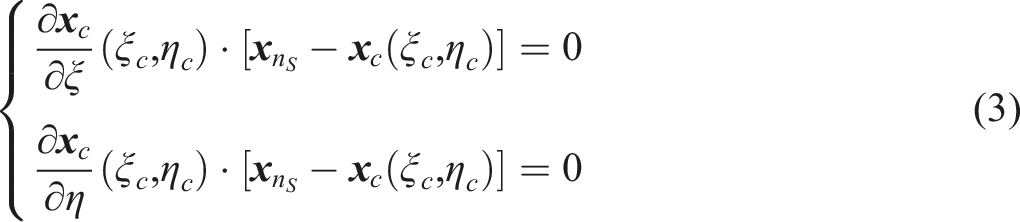
The dot product Schematic diagram of flow field reconstruction and information update.

In addition, in order to ensure that the flow field always wraps the structural domain and moves with it, the transformation matrix

Case study
Generally, the design manuals recommend the value of LWR to be 3.0–3.8.1,2 But, in actual projects, the value of LWR is almost large. As described in the design manual, the values of LWR in the two actual cases are 3.9 and 4.6, respectively.
2
The main purpose of this work is to study the influence of the design parameter LWR on deceleration performance and terminal trajectory stability. Therefore, the value range of LWR is expanded and two limit values are added in this work. Here, five different LWR cruciform parachutes are used for research (Figure 3), and the LWRs are 2.28, 3.06, 3.78, 4.5, and 5.22, respectively. The remaining design parameters and material parameters of the above five models are exactly the same. The total area of all cruciform parachutes is 1.28 m2, the fabric elastic modulus is 0.42 GPa, the thickness is 0.4 mm, and the air permeability of the fabric is 0.327 m/s under the pressure difference of 49 Pa (Russian standard). The parachute cord length is 1.4 m (total 12 cords), and the elastic modulus of cord is 0.6 GPa. Illustration of geometric parameters of cruciform parachutes with different LWRs.
Subsequently, this work establishes finite element models of the folded parachute system based on the above geometric parameters, in which the canopies are discretized by triangular elements with same size. And the number of canopy elements of different designs is between 7900 and 8500. The flow field is discretized by 930,600 hexahedral elements. The flow field and the structure are assembled by interpenetrating with each other (Figure 4). The projectile mass is 7.5 kg, the initial trajectory angle is 60°, the initial speed is 300 m/s, and the flight time of the projectile in the air is 3.5 s. In addition, this work also considers the impact of downwind (+Y direction) and upwind (-Y direction) with 8 m/s on deceleration performance and terminal trajectory stability. Calculation model after assembly (LWR: 5.22).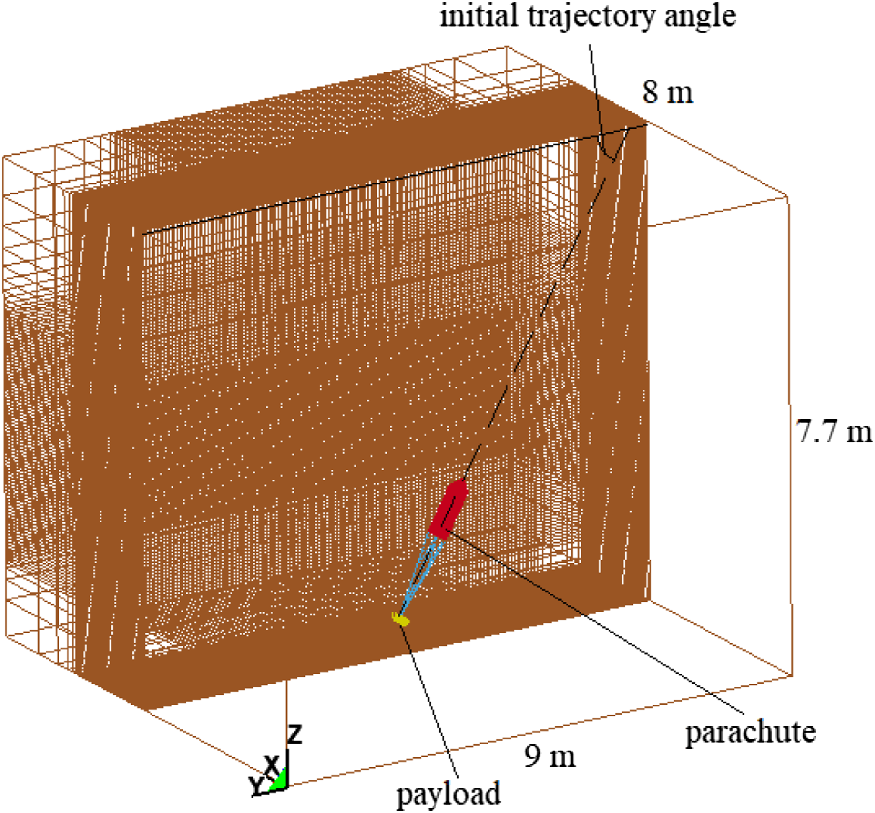
Results and discussions
Analysis of the terminal trajectory of the projectile
Figure 5 shows the comparison of the projectile’s terminal trajectory and resultant displacement. The host graph is the comparison of the projectile’s terminal trajectory, and the upper left sub-graph is the comparison of the projectile’s resultant displacement. Comparison of terminal trajectory and resultant displacement (a). Model 2.28; (b). Model 3.06; (c). Model 3.78; (d). Model 4.5; (e). Model 5.22; (f). no wind condition.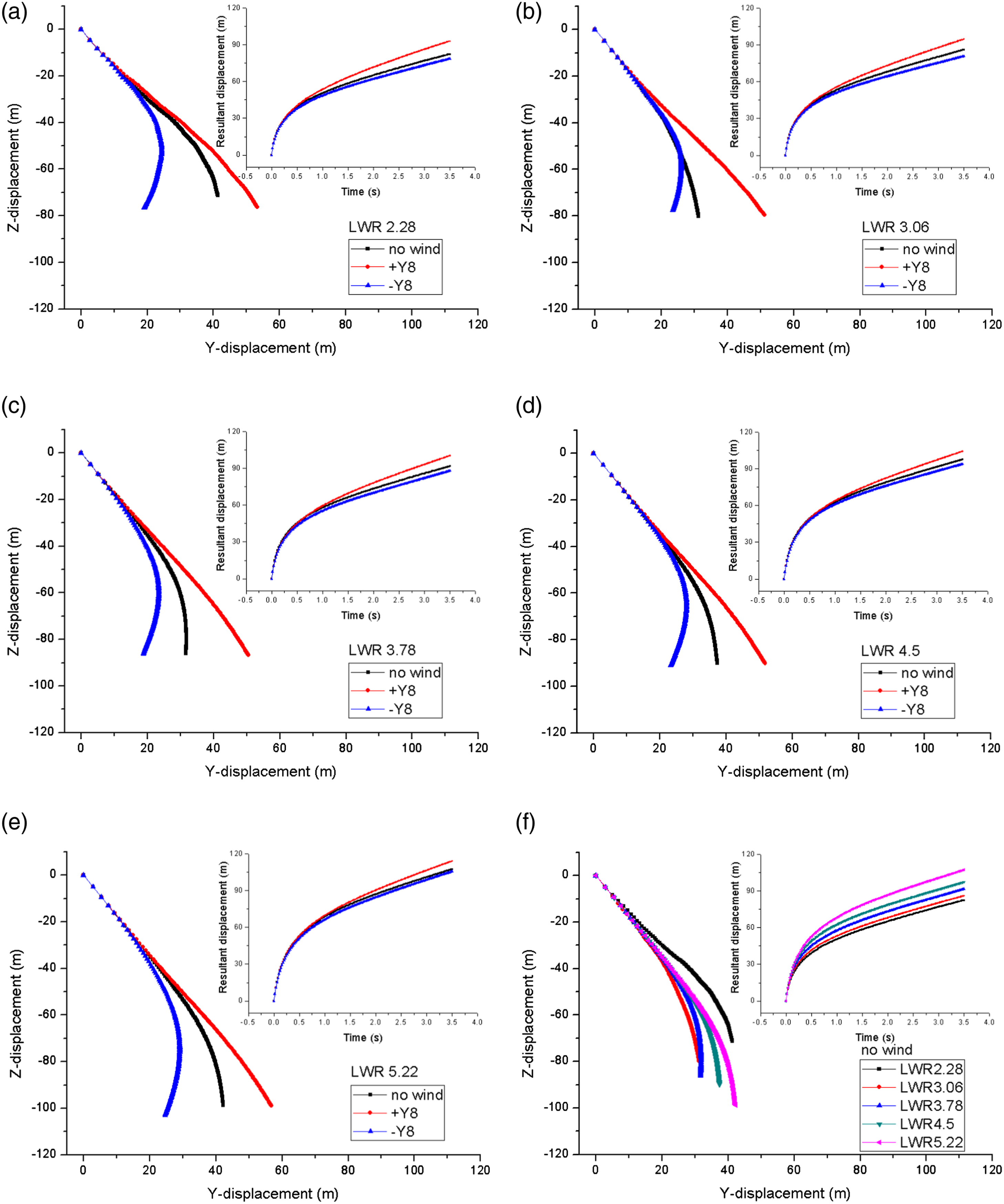
From Figure 5(f) (upper left sub figure), it can be found that the resultant displacement of the model with an LWR of 5.22 (hereinafter referred to as Model 5.22, other models are named similarly) is 107.48 m, while the resultant displacement of Model 2.28 is 82.41 m. The maximum difference between those two models can be up to 25.07 m. And the former is almost 1.3 times than that of the latter, while the resultant displacements of the other models are between those two models. And the resultant displacement increases with the increase of the design parameter LWR. This indicates that under the condition that the canopy area, material and other designs are exactly the same, the smaller the LWR, the stronger the deceleration ability of the cruciform parachute. From the perspective of the influence of the external wind field on the resultant displacement of the projectile (Figure 5(a)–€), the resultant displacements are in order of downwind conditions, no wind conditions and upwind conditions. The maximum difference of the resultant displacements of all models does not exceed 15m. Therefore, the influence of the external wind field on the resultant displacement is less than the design parameter LWR.
Comparison of the time required to reach 70 m height and the maximum horizontal displacement difference.

In addition, it is obvious from the trajectory comparison shown in Figure 5. As the LWR increases, the terminal trajectory curve changes more smoothly. The Model 2.28 trajectory curve (Figure 5(a)) has slight mutations locally, which leads to irregularity in the trajectory comparison of all models under windless conditions (Figure 5(f)). This is mainly due to the poor stability of Model 2.28 itself.
Analysis of the deceleration characteristics of the projectile.
Figure 6 shows the comparison of the resultant acceleration and acceleration components of the projectile. The host graph is the comparison of the resultant acceleration of the projectile, and the upper left sub-graph is the comparison of the acceleration components in the Z direction and the Y direction of the projectile. Comparison of resultant acceleration and acceleration components (a). Model 2.28; (b). Model 3.06; (c). Model 3.78; (d). Model 4.5; (e). Model 5.22; (f). no wind condition.
It can be found that the acceleration change trend of the same model under windless, downwind and upwind conditions is basically the same (Figure 6(€(e)). Due to the additional drag generated by the wind field, the upwind condition causes the projectile’s overload to be slightly higher than the windless condition and the downwind condition. Therefore, the inherent deceleration characteristics are extremely limited by the external wind field. Meanwhile, it can be found that the canopy area of all models is exactly the same, and the projectile reaches its maximum acceleration almost at the same time in Figure 6(f). And the maximum resultant acceleration values (arranged from small to large according to LWR) are 3026.4 m/s2, 2744 m/s2, 2495.6 m/s2, 225.3 m/s2, and 2046.9 m/s2, respectively. The smaller the LWR value, the greater the maximum overload that the projectile has, and the faster the overload decreases. However, as the parachute system enters the steady dropping stage after 0.6 s, the acceleration curve of each model does not change much. This shows that the smaller the LWR, the stronger the deceleration ability of the cruciform parachute, and the higher the deceleration efficiency.
According to the flow field results at the time of maximum overload (0.02s) of each model projectile reached, it can be found that Model 2.28 is the first to complete the canopy inflation. The canopy arm of Model 2.28 is the shortest (only 1.366 m), but the canopy can form an efficient aerodynamic deceleration surface. That the outflow of air inside the canopy is blocked, forming a high-pressure area inside, and the low-pressure area formed by the external turbulence causes the Model 2.28 to form a relatively large aerodynamic drag in a short time (Figure 7(a)). As the LWR increases, more and more air inside the canopy can flow out from the gaps between canopy arms. Therefore, it is difficult to form a high-pressure zone again (Figure 7(a)–(e)). At the same time, the increase in LWR means that the longer the parachute arm with the same area (Figure 3). The long canopy arms will further hinder the surrounding air from entering the inside of the canopy at the bottom. Even a local high-pressure area is formed outside the canopy, which further extends the inflation time of the cruciform parachute. The smaller the LWR, the shorter the inflation time of the cruciform parachute, and the higher the deceleration efficiency. However, the smaller LWR design would lead to greater overload and stress, which will put forward higher requirements for the strength design of the whole system. Comparison of pressure contour, velocity vector and effective stress contour at 0.02s under windless condition (a). Model 2.28; (b). Model 3.06; (c). Model 3.78; (d). Model 4.5; (e). Model 5.22.
Figure 8 shows the comparison of the resultant velocity and velocity components of the projectile. The host graph is the comparison of the resultant velocity of the projectile, and the upper left sub-graph is the comparison of the velocity components on the Z direction and the Y direction. In the initial stage of deceleration, the projectile speed of the same model in the downwind conditions is slightly higher, and the speed in the upwind conditions is slightly lower (Figure 8(a)–(e)). Meanwhile in the early stage of deceleration, the smaller the LWR, the higher the deceleration efficiency of the cruciform parachute, and the lower the speed of the projectile (Figure 8(f)). However, after 0.6s, as the deceleration process enters the steady dropping stage, the above-mentioned speed curve changes gradually stabilize, and the difference gradually becomes smaller. At about 3.5 s, the steady dropping speed of all models remains at 12–13.8 m/s. In the end, the speed curves of all models show that the external wind field has a limited effect on deceleration, but the steady dropping speed is positively correlated with LWR. Comparison of resultant velocity and velocity components (a). Model 2.28; (b). Model 3.06; (c). Model 3.78; (d). Model 4.5; (e). Model 5.22; (f). no wind condition.
Analysis of cruciform parachute stability
Figure 9 shows the comparison of the oscillation angle and trajectory angle of the cruciform parachute. The host graph is the comparison of the oscillation angle and the sub-graph in the upper left is the comparison of the trajectory angle of the cruciform parachute. Comparison of oscillation angle and trajectory angle (a). Model 2.28; (b). Model 3.06; (c). Model 3.78; (d). Model 4.5; (e). Model 5.22; (f). no wind condition.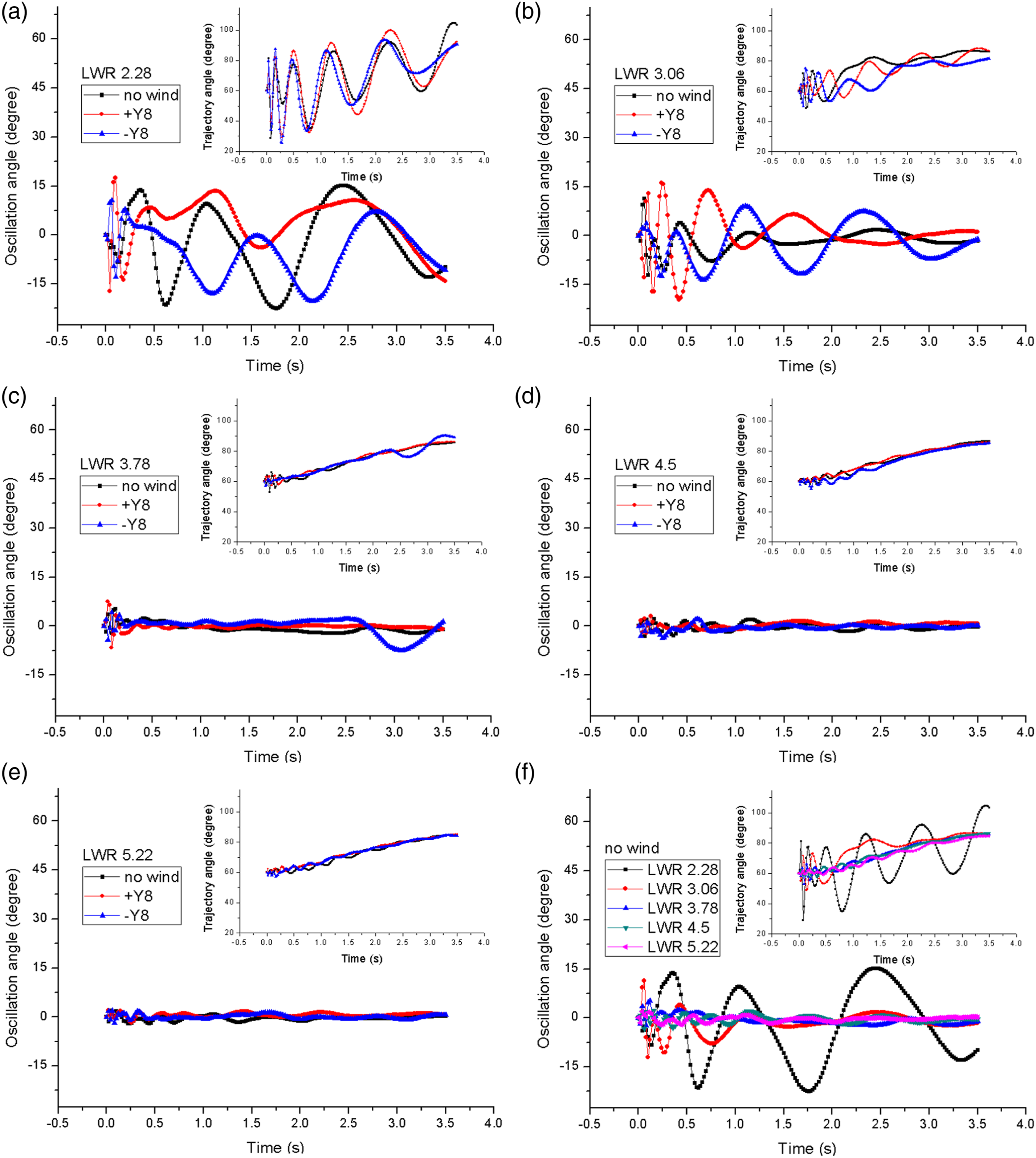
From the comparison of the oscillation angle, it can be found that the oscillation angle change frequency of all models is higher in the early stage of deceleration. However, as the cruciform parachute enters the steady dropping stage, the oscillate frequency decreases, and the external wind field has little effect on the change of the cruciform parachute oscillation angle (Figure 9(a)–(e)). The design parameter LWR has a greater influence on the oscillation angle amplitude. The larger the LWR, the smaller the oscillation amplitude of the canopy during the steady dropping stage (Figure 9(f)). This shows that the stability of the canopy itself is positively correlated with the design parameter LWR.
The changing law of the trajectory angle of the canopy is also the same as the changing law of the oscillation angle. The trajectory angle of all models changes from the initial 60°–90°. In this process, the influence of the additional aerodynamic drag caused by the external wind field on the deceleration characteristics also becomes weaker. This also explains the reason that the velocity or acceleration difference caused by external wind gradually becomes smaller in steady dropping stage (Figures 6 and 8). However, the difference in the terminal trajectory of the projectile does not decrease (Figure 5), and the influence of the external wind field on the terminal trajectory can be divided into indirect and direct influence. In the early stage of parachute dropping, due to the existence of an initial trajectory angle other than 90°, the external wind field will form additional aerodynamic drag on the tangent direction of the trajectory, which directly affects the deceleration characteristics and indirectly affects the trajectory. In the steady dropping stage, the additional aerodynamic drag gradually disappeared and the external wind field hit the canopy vertically, which directly affects the trajectory.
According to the above analysis, it can be found that the design parameter LWR has a greater influence on the stability of the cruciform parachute. The canopy stability will further affect the trajectory stability of the projectile. This also explains the reason that the curve changes of Model 2.28 shown in Figure 5(a), Figure 6(a) and Figure 8(a) are not smooth. However, this conclusion only applies to models with smaller parameter of LWR.
According to the results of Model 3.78 in upwind conditions (Figure 9(c)), it can be found that the oscillation angle and trajectory angle of the canopy change drastically at 2.6s. This change has almost no effect on the trajectory stability and deceleration characteristics of the projectile. The reason for this dramatic change is that there was a partial twist at the bottom of the canopy at that moment. Meanwhile, Model 3.78 has a larger gap between the canopy arms, and the high-pressure area at the top of the parachute cannot expand downward to the bottom (Figure 10). The slack bottom cannot be restored to its original shape in a short time, and then the asymmetric flow at the bottom aggravates the instability of the cruciform parachute. The Model 4.5 and Model 5.22 also have bottom slack or local twist in different working conditions. However, their arms are relatively longer and the windward area at the bottom is smaller, and the slack bottom of the canopy has limited influence on its own stability. Aerodynamic shape and pressure contour of Model 3.78 at 2.62s.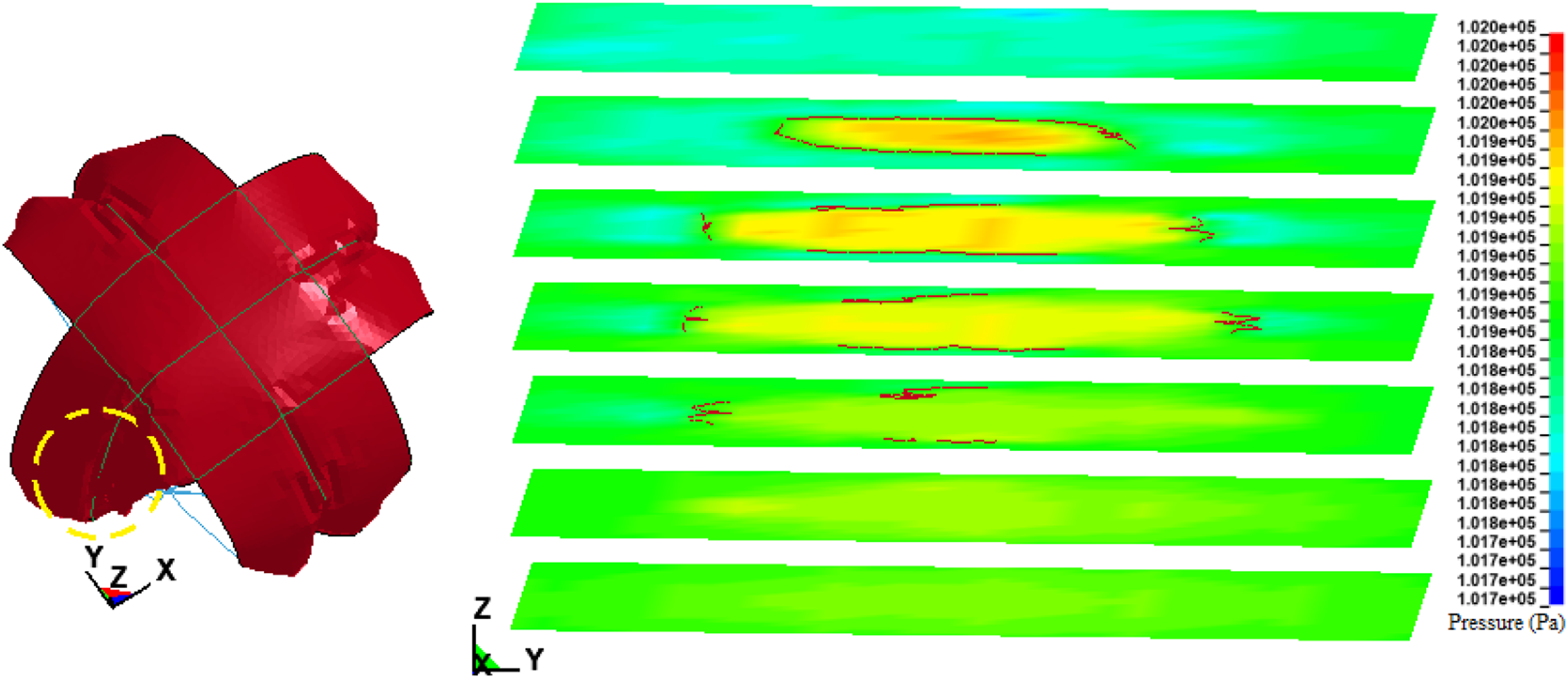
Therefore, the smaller the design parameter of LWR, the worse the stability of the cruciform parachute. While the influence of the parachute stability on the trajectory stability and deceleration decreases with the increase of LWR.
Quantitative analysis of deceleration characteristics of cruciform parachute
In order to verify the accuracy of the numerical method, Model 4.5 is used for airdropping experiment. The experiment conditions are the same with the calculation conditions shown in Analysis of cruciform parachute stability section. But the direction and speed of external wind field are uncontrollable, and the wind speed near the ground is about 5 m/s in airdropping experiment. In addition, due to the limitations of the experiment conditions and consideration of safety factors, only the steady dropping speed is obtained based on the high-speed camera records. The experimental value of 13.5 m/s is relatively close to the calculation value of Model 4.5 (12.6–13.5 m/s).
In order to further analyze the influence of other factors on the deceleration characteristics, this work continues to take Model 4.5 as the research object. The deceleration processes of the projectile with different initial trajectory angles and different external wind field are calculated. From the calculation results shown in Figure 11, it can be found that the initial trajectory angle and wind speed have almost no effect on the deceleration of the projectile. The additional drag caused by the wind field only has an impact on the early stages of deceleration. When the parachute system enters the steady dropping stage, the speed difference is further reduced. The final speed difference is even smaller than that caused by parameter of LWR (Figure 8(f)). Comparison of the resultant velocity and acceleration of the projectile with different initial trajectory angles and external wind field.
Based on the results shown in Figure 6, Figure 8, and Figure 11, it can be found that the external wind field has a limited impact on the deceleration ability of the cruciform parachute. LWR is another design parameter that has a greater impact on the deceleration performance of the cruciform parachute after the canopy area. Finally, the correction equation (6) of drag coefficient Fitting of correction equation of drag coefficient.

Conclusion
The fluid structure coupling method is used to analyze the influence of the design parameter LWR on the deceleration performance and terminal trajectory stability of the cruciform parachute in this work. Then, based on the calculation results, the drag coefficient correction equation that characterizes the deceleration performance is obtained for the first time. The main conclusions of this work are as follows: 1. As an important design parameter of the cruciform parachute, the LWR directly determines the deceleration characteristics of the cruciform parachute. The external wind field (wind speed and direction) and initial working conditions (initial trajectory angle) have limited influence on the deceleration characteristics of the cruciform parachute. 2. The external wind field has an indirect influence on the trajectory in the early stage of dropping, and a direct influence on the steady dropping stage. But the influence of the external wind field on the projectile stability is not as good as the design parameter LWR. The smaller the LWR, the stronger the trajectory stability. 3. The LWR has a greater impact on the stability of the cruciform parachute, while the external wind field has a smaller impact on the stability of the cruciform parachute.
In summary, under the premise that the other design parameters and dropping conditions are completely the same, the deceleration performance is negatively correlated with the LWR, and the trajectory stability and the stability of the cruciform parachute are positively correlated with the LWR.
Footnotes
Declaration of Conflicting Interests
The author(s) declared no potential conflicts of interest with respect to the research, authorship, and/or publication of this article.
Funding
The author(s) received no financial support for the research, authorship, and/or publication of this article.