
Abstract
In recent decades, electromagnetic wave pollution has become more and more serious. In order to reduce the adverse effects of these waves, the nickel–iron/polymers of p-phenylene terephthamide (PPTA)–blended single yarn and plied yarn were manufactured, and the nickel–iron fibers with various contents (10%, 15%, and 20%) as raw materials were used. Nickel–iron/PPTA-blended yarns were knitted with three knit structures and three looped deep (11.25, 11.50, and 12.00 mm). The electromagnetic absorption effect was examined using the reflectance arch method at a frequency range between 2 and 18 GHz. The results show that the fabric with plied yarn, nickel–iron fiber content of 10%, looped deep of 12.00 mm, and loop notation of structure C has the best electromagnetic wave absorption performance, which can reach −30 dB reflectivity at 5.1 GHz, and the bandwidth with reflectivity lower than −5 dB reaches 2.5 GHz. In order to make the fabric obtain more functions, water-repellent treatment of the fabric is carried out. The results show that the best finishing effect can be obtained by using 40% water repellent and drying at 170°C for 5 min so that the sample can resist the hydrostatic pressure of 49.1 kPa. Finally, through the vertical burning test, the flame retardancy of the fabric can reach level B1.
Keywords
Introduction
Nowadays, with the rapid development of science and technology, various electronic devices have been widely used. However, while providing convenience for people, these electronic devices also produce a large amount of electromagnetic radiation. These electromagnetic radiations will have a negative impact on people’s health, while affecting the operation of other electronic equipment, resulting in electromagnetic pollution. 1
Absorbing material is a kind of functional material that can absorb electromagnetic waves and convert the energy of electromagnetic waves into heat energy. It can not only reduce electromagnetic pollution but also has a wide application in radar stealth technology.2,3 However, when absorbing materials are used in different outdoor environments, such as absorbing tents in rainforests and deserts, to achieve radar stealth effect, absorbing materials often lose their absorbing function due to accelerated aging in humid and high-temperature environment. Therefore, it is of great significance to develop new absorbing materials with composite functions, such as water-repellency and flame retardancy.
Electromagnetic wave-absorbing materials mainly rely on electric loss or magnetic loss to obtain the absorbing effect, which can be roughly divided into the following types according to the different types of constituent materials: metallic absorbing materials, such as ferrite,4–6 nickel, and7,8 cobalt;9–11 carbon absorbing materials, such as carbon fiber, 12 graphene, and 13 carbon nanotubes; 14 ceramic absorbing materials, such as silicon carbide; and 15 conductive polymer absorbing materials, such as polyaniline,16,17 polypyrrole, 18 plasma materials, and 19 chiral materials 20 . There are many ways to prepare electromagnetic wave-absorbing materials, including blending, chemical plating, and coating. Among them, textile-absorbing materials have high flexibility, easy portability, and can be mass-produced, so it has certain advantages. Sometimes, it is difficult for a single material or method to meet the requirements of some properties of materials, so a combination of multiple materials or methods can be used to solve such problems.21,22
Microwave-absorbing textiles are less studied in microwave-absorbing materials. Ding DH et al. 23 prepared KD-I SiC fiber fabrics and tested the microwave absorption performance. The results show that the fabric achieves the lowest reflection loss of −25.4 dB at 10.3 GHz, and its absorbing frequency band is about 4 GHz. Li WP et al. 24 coated 85 wt% modified CIP on non-woven fabric and tested the microwave absorption performance of the fabric. The results showed that non-woven fabric-absorbing material has a reflection loss of −26 dB with the matching thickness of 2.08 mm at 9.35 GHz. In other literature, it has been reported that the shielding efficiency of the flexible fabrics made from cotton–stainless steel core yarn could be tailored by the fabric design, and the developed shields could mitigate very-high frequency (VHF) to ultrahigh frequency (UHF) bands of electromagnetic waves to the extent of 55%. 25
Nickel and iron are both good absorbing metal materials, but most of them are in the form of metal powder. At present, there is little research on using the nickel–iron fiber to prepare absorbing materials directly. In fact, the nickel–iron fiber possesses pretty high permeability and low coercivity. As an anisotropic material, its electromagnetic parameters can be changed by adjusting the length and diameter, making it become an excellent wave-absorbing material. 26 Most importantly, the cost of producing nickel–iron fibers is much lower than that of metal powder and can be produced in large quantities. Therefore, this article innovatively uses the nickel–iron fiber as the main absorbing material. Next, polymerization of p-phenylene terephthamide (PPTA) itself is flame retardant, and its structure has a high limiting oxygen index, which can inhibit the cracking of large molecules into flammable small molecules, making the fiber difficult to be ignited. Besides, it also has high tensile strength, high wear resistance, as well as corrosion resistance 27 . As a result, the excellent performance of PPTA introduced above could make up for the shortcomings of the nickel–iron fiber such as low strength and high brittleness, so it is quite possible to blend nickel–iron fibers and PPTA fibers into yarn. And, the fabric made of this yarn possesses both wave absorption and flame-retardant properties. At present, people are committed to the study of flexible absorbing materials. Compared with woven fabrics, knitted fabrics have higher flexibility and ductility. Therefore, knitted fabrics are used as the research object in this study. Beyond that, water-repellent finishing is also required in order to increase the water-repellent performance of the fabric.
In this study, the textile is made of nickel–iron fibers and PPTA fibers for the first time. First, the nickel–iron fiber and PPTA fiber were blended, and the basic physical properties of the blended yarn were tested. Then, different kinds of fabrics were knitted with different content of nickel–iron fiber (10%, 15%, and 20%), weft-knitted structure (all three structures comprise 1 × 1 rib stitch and different Jersey stitch), looped deep (11.25 mm, 11.50 mm, and 12.00 mm), and single or plied yarn. The physical properties and absorbing properties of the fabrics are tested. Therefore, the fabric with better absorbing property is selected for water-repellent finishing, and the optimal finishing scheme is explored. Finally, the flame retardancy of the fabric was tested, and the standard was judged.
Experimental materials and methods
Parameters of fibers used in the experiment
X-ray diffraction data of the nickel–iron fiber.

Yarn spinning process
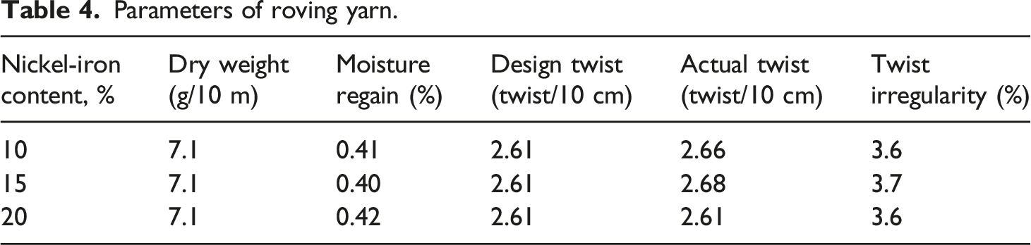
Nickel–iron fibers and PPTA fibers were blended into yarn by ring spinning. The technological process and parameters are shown in Figure 1 and Tables 2–4. Considering the mechanical properties of the fabric, the yarn linear density is determined to be 59 Tex. After repeated tests, when the proportion of the nickel–iron fiber exceeds 25%, the spinning process is difficult because of the greater rigidity of the metal fiber. Therefore, 10%, 15%, and 20% nickel–iron fibers and PPTA fibers are blended into yarns. To achieve this effect, two types of nickel–iron card sliver, 2.0 g/m and 5.8 g/m, respectively, with fiber length of 38–40 mm and two types of PPTA card sliver, 3.6 g/m and 4.6 g/m, respectively, with fiber length of 37–40 mm were used. After the nickel–iron/PPTA blended yarn is produced, the strength and elongation of the yarn are tested. Process flow of nickel–iron/PPTA blended yarn. Yarn sample preparation. Drawing process parameters. Parameters of roving yarn.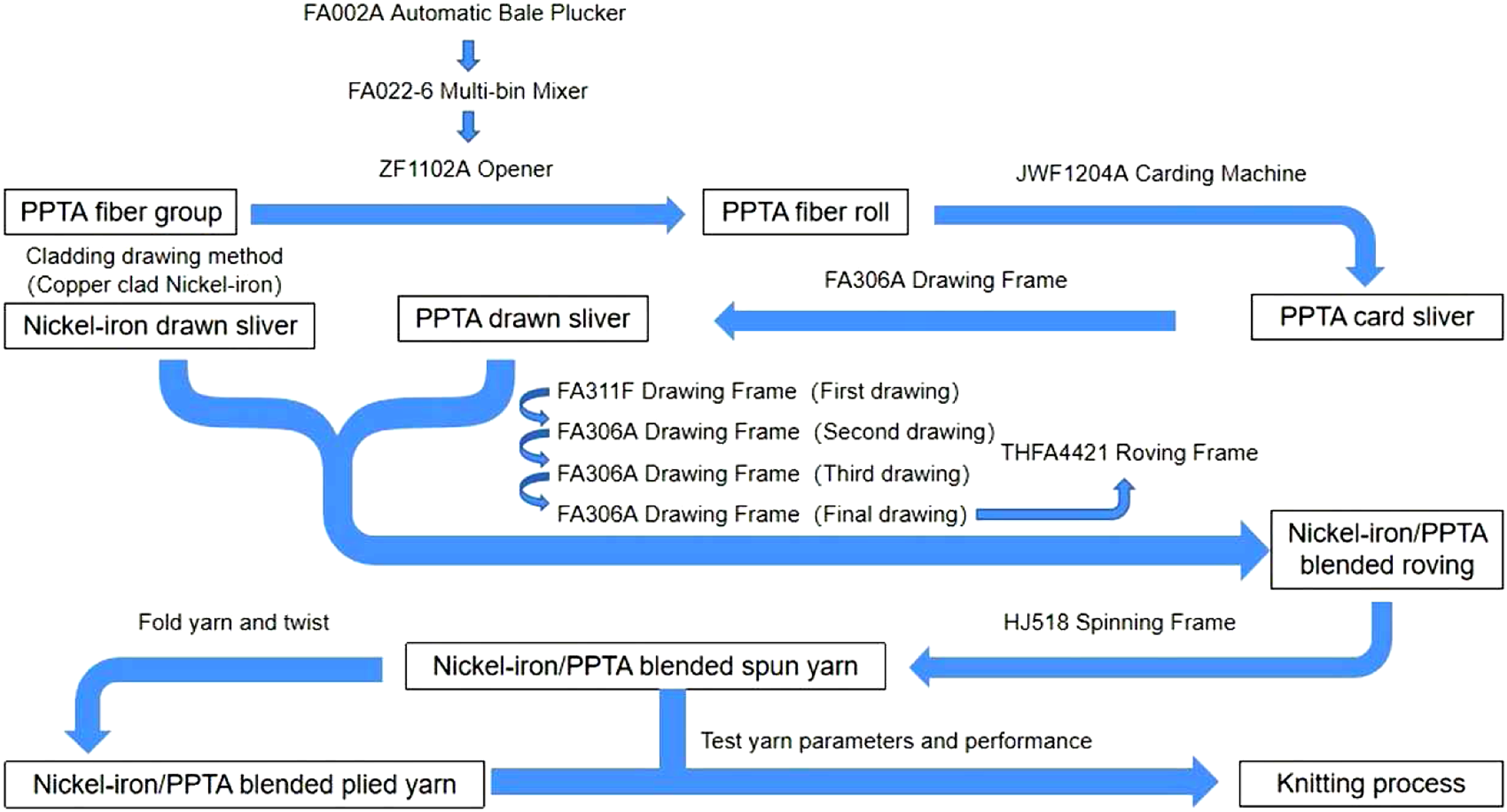


Preparation of microwave-absorbing knitted fabric
The weft-knitted fabrics were obtained by using a Stoll CMS 530 HP E 7–14 computer-controlled flat knitting machine, and the fabric design and settings were programmed on an M1plus pattern station. The WMF value of the machine is set to 3. Considering that the knitted fabric is made up of yarn in loops and the organization with different looped deep (the vertical distance between the jaw of the sinker and the inner point of the needle hook when the needle descends to its lowest point) will lead to different fabric density and thickness, which will affect the absorbing effect of the fabric, the article explores the absorbing performance of the knitted fabric. The content of the nickel–iron fiber, looped deep, and the kinds of structures are taken as variables. Single yarn and plied yarn are knitted separately to find out the fabric with the best electromagnetic wave absorption effect. Among these variables, the content of the nickel–iron fiber was 10%, 15%, and 20% The looped deep is 11.25 mm, 11.50 mm, and 12.00 mm.
This article also designed three weft-knitted structures as the test variables; their loop notations are shown in Figure 2. Strictly speaking, these three structures are not standard weft-knitted structures. Structure A is comprises two 1×1 rib stitch knitting systems and four Jersey stitch knitting systems, in which the upper needles of the first and fourth knitting systems do not work, and only the lower needles with even numbers work; the lower needles of the 2nd and 5th knitting systems do not work, and only the upper needles with even numbers work; the 3rd and 5th knitting systems are 1×1 rib stitch. Structure B comprises one 1×1 rib stitch knitting system, and four 1×1 knit Miss Jersey knitting systems, in which the upper needle of the first and second knitting systems does not work, and the lower needle works at intervals; the lower needle of the 3rd and 4th knitting systems does not work, and the upper needle works at intervals. The 5th knitting system is a 1×1 rib stitch. Structure C is similar to structure B, and both have a 1×1 rib stitch knitting system. The difference is that 1×1 knit Miss Jersey has become a 2×2 knit Miss Jersey knitting structure, and the number of knit Miss Jersey knitting systems has increased from 4 to 6. Loop notations of the weft-knitted structure.
A total of 18 kinds of fabrics are knitted, each of which is 180 mm × 180 mm in size. The wales per 5 cm, courses per 5 cm, loop length, mass per unit area (GSM), thickness, strength, and elongation (warp direction) properties of these samples were tested and recorded.
Test method for electromagnetic wave reflectivity of fabrics
Reflectivity is an important index to characterize the absorption properties of materials. With certain transmittance, the lower the reflectance, the better the absorption. It is more convenient to use the reflectance arch method to test the sample of fabric flat sheet material. The schematic illustration of the reflectance test principle of the arch method is shown in Figure 3. The reflection power of the sample and conductive metal platform can be obtained by transmitting and receiving electromagnetic waves. The reflectivity of the sample is then calculated according to equation (1). The test ranges from 2 to 18 GHz, the most common radar wave range (including S, C, X, and Ku four Chinese microwave standard band). Schematic illustration of the reflectance test principle of the arch method.

Test method for water-repellent finishing of fabrics
After the electromagnetic wave-absorbing capability test, the sample with the best wave absorption performance was selected for the water-repellent finishing test. In this test, the type of water-repellent agent used is Organic Fluorine DM-3640C. Using the method of double-dip–double-nip, the liquid carrying rate (the ratio of the weight of liquid carried by the fabric after dip rolling to the original weight of the fabric) is 50%. After the waterproof finishing of the fabric, the water penetration resistance (hydrostatic pressure) of the sample was tested.
In order to explore the best water-repellent finishing process, three different variables were designed in this experiment. They are water-repellent finishing agent (20%, 40%, and 60%), drying temperature (130°C, 150°C, and 170°C), and drying time (3 min, 5 min, and 7 min). Due to the large number of experimental combinations, a lot of samples will be wasted if all the experiments are carried out. Therefore, an orthogonal experimental design is adopted, which only needs to carry out tests of nine schemes. For the sake of accuracy of the data, each test was repeated three times, and the average value was taken as the test results.
Test method for flame retardancy of fabrics
According to the GB/T 5455–2014 “Vertical Combustion Method” (Chinese standard), the test sample is flame retardant. The specimen was exposed to a flame with a height of (40 ± 2) mm for 12 s, and then the damage length, afterglow time, and afterflame time parameters of the specimen were measured.
The experiment includes all contents from fiber to preparation of electromagnetic wave absorption, water-repellent, and flame-retardant knitted fabric. The experimental process is shown in Figure 4. Whole process of multifunctional electromagnetic wave-absorbing fabric preparation.
Results and discussion
Nickel–iron/PPTA-blended yarn test results
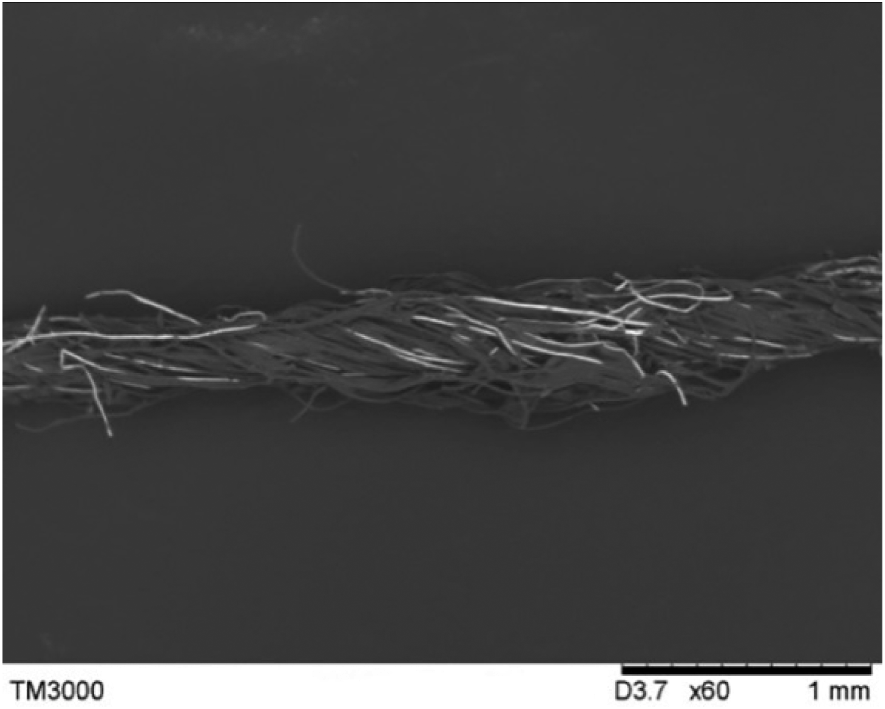
The picture and SEM image of nickel–iron/PPTA-blended yarn produced in the test are shown in Figures 5 and 6. The strength and elongation of yarn are shown in Table 5. It can be seen that with the increase in nickel–iron fiber content and the decrease in PPTA fiber content in the blended yarn, the yarn strength decreases gradually. This is because PPTA fibers are much stronger than nickel–iron fibers. The decline in yarn strength also has an adverse effect on the subsequent weaving process. Therefore, considering the adverse effect of the metal fiber on spinning and knitting process, the content of the nickel–iron fiber should be controlled within 20%. Nickel–iron/PPTA-blended yarn produced in the test. SEM image of nickel–iron/PPTA-blended yarn. Test results of blended yarn properties.

Knitted fabric test results
The knitted fabric samples produced are shown in Figure 7, and their parameters and properties are shown in Table 6 (numbers 1–9 are knitted by single yarn, 10–18 are knitted by plied yarn). As can be seen from Table 6, first, the GSM and thickness of the sample are consistent, that is, the fabric with large GSM is also thicker. Second, the yarn type has the greatest influence on the different properties of the fabric. The GSM, thickness, breaking strength, and elongation of the sample made of plied yarn are significantly higher than those made of single yarn. On this basis, the two samples with the largest GSM and thickness in the single yarn fabric (1–9) are 5 and 7 and 14 and 16 in plied yarn fabric (10–18). Their common point is that they all have knit structure C. Knitted fabric samples produced in this test. Parameters of different kinds of samples.

All three knit structures have floats; the wales are drawn closer together by the floats. The length of floats in knit structure C is longer, which not only reduces the walls per center of knit structure C but also increases loop length. The decrease of wales per centimeter will reduce the fabric thickness and GSM, but the increase in coil length will increase the fabric thickness and GSM. Most importantly, in knit structure C, three knitting systems (knitting systems 1–3 are a group and 4–6 are a group) form a complete pattern of horizontal, while in knit structure A and B, only two knitting systems (A: 1–2,4–5; B: 1–2,3–4) form a complete pattern of horizontal. This makes the courses per centimeter of knit structure C much higher than those of A and B, and increases the thickness of the fabric. The increase of courses per centimeter and thickness also increases the GSM value of the fabric. Therefore, it can be concluded that knit structure C can increase the GSM and thickness. Finally, due to too many variables, the influence of a single parameter on fabric strength and elongation is not obvious.
Electromagnetic wave-absorbing capability of samples
The electromagnetic wave-absorbing capability is represented by the reflectivity of the sample. In the frequency–reflectivity curve, the lowest point of the curve where the minimum dB value is represents the best wave-absorbing capacity of the sample in the frequency band. Comparing the electromagnetic wave-absorbing capability of samples which are divided by the type of yarn, the results are given in Figures 8 and 9. Electromagnetic wave-absorbing capability of samples by single yarn. Electromagnetic wave-absorbing capability of samples by plied yarn.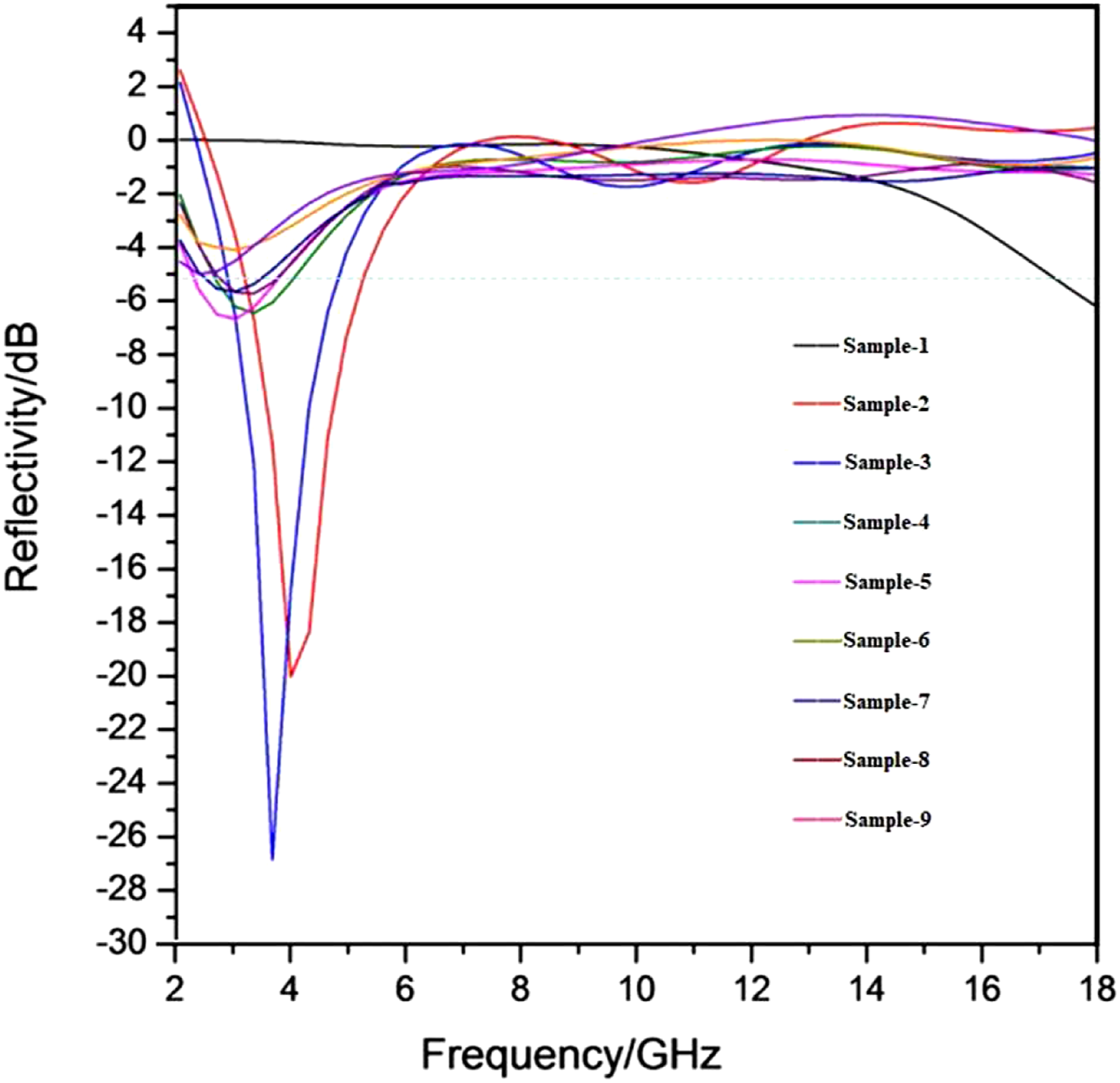

Since the total reflection plate is placed below the sample in this experiment, the transmittance is negligible, so the reflectance and absorptive are equal to 1. Figure 8 shows the dB value of the electromagnetic wave reflection of samples woven with single yarn. Obviously, in the 2–6 GHz frequency band, all the samples, except sample 1, have certain electromagnetic wave-absorbing performance, especially samples 2 and 3, while sample 1 shows absorbing performance at the frequency band of 14–18 GHz. Among these samples, sample 3 has the best microwave absorption performance: the bandwidth with reflectivity lower than −5 dB (absorption higher than 68.4%) reaches 2 GHz (2.9 GHz–4.9 GHz), and the lowest −26.90 dB (absorption 99.8%) reaches 3.6 GHz.
Figure 9 illustrates the dB value of the electromagnetic wave reflection of samples woven with plied yarns. It can be seen from the results that in addition to samples 15 and 16, other samples show good electromagnetic wave absorption effect in the 2–8 GHz frequency band, while samples 15 and 16 have certain electromagnetic wave absorption ability in the 14–18 GHz frequency band. In this group of samples, it is clear from the results that sample 12 has the best microwave absorption performance: the bandwidth with reflectivity lower than −5 dB reaches 2.5 GHz (4.1 GHz–6.6 GHz), and the lowest −30.00 db (absorption 99.9%) reaches 5.1 GHz.
From Figures 8 and 9, we can find that sample 3 and sample 12 have the best microwave absorption performance in the single yarn group and plied yarn group, respectively. They have the same knitting parameters, that is, nickel–iron content of 10%, yarn looped deep of 12.00 mm, and C fabric structure. These parameters are beneficial to their microwave absorption properties. Comparing the microwave absorption performance of sample 3 and sample 12, sample 12 has more advantages in both the absorption bandwidth and the lowest reflectivity. This is because the plied yarn fabric is thicker and the electromagnetic wave can be absorbed more when passing through the fabric.
Water repellency of samples
Results of water-repellent finishing tests.

Results of the orthogonal experiment analysis.

Ki: Sum of test results measured in the i level test for factor X. For example, for factor A: K1 = 328+349+338+329+350+349+345+397+387 = 3172. ki = Average of Ki. For example, for factor A: k1=K1/9=352.4. Range: Difference between maximum and minimum values of factor X. For example, for factor A: Range = 421–352.4 = 68.6.
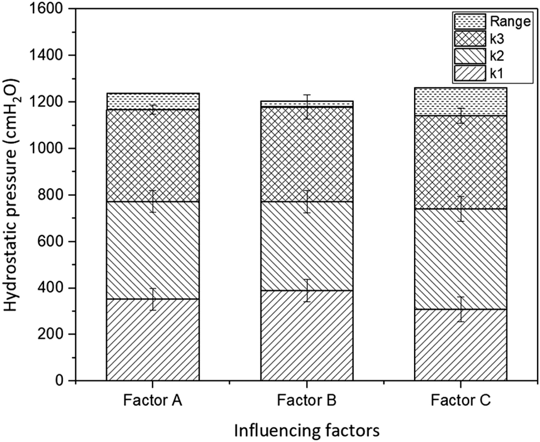
Average and range of level number of factors.
According to the definition of the main effect, the greater the range, the larger the influence of the factor on the results of the test. It is clear from Table 8 and Figure 10 that range(C) > range(A) > range(B). Therefore, the effect of the studied factors for the fabric water-repellent effect is ranked as C > A > B. It is also found that k2(A), k3(B), and k2(C) were the largest of the mean values of all test results at each level; this represents the optimum process: Concentration of the water-repellent finishing agent: 40%, drying temperature: 170°C and drying time: 5 min. When the best process is adopted, the hydrostatic pressure that the sample can resist is 501 cmH2O, about 49.1 kPa (1 kPa = 10.2 cmH2O).
Hydrostatic pressure rating and water resistance evaluation of samples.

Flame retardancy of samples
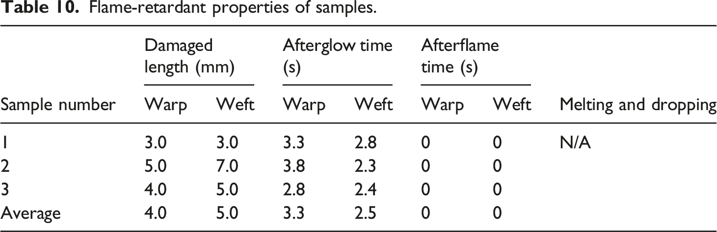
The flame-retardant property of three fabrics is tested which is the same as 12 samples after water-repellent finishing. The sample after the experiment is shown in Figure 11. The results (Table 10) show that the damaged length of the three samples cited are same in both warp and weft direction, but the warp way after glow time is longer than that found with the weft way. The result of this reason is that in the vertical combustion test, the flame will cover an upward area at the bottom of the fabric. The width of this area is narrow, and the height is high. The courses per centimeter of sample 12 are much larger than wales per centimeter. Therefore, when burning along the meridional direction, the number of loops contacted by the flame is greater than that along the latitudinal direction. These loops need a certain time to end the combustion after removing the fire source, Therefore, the warp way after glow time is longer than that found with the weft way. The average value of damaged length of the sample is less than 15 cm, both afterglow time and afterflame time are less than 5 s, without melting and dropping. All the indexes are up to the standard of the flame-retardant fabric B1 level (Table 11) to show that the sample has excellent flame-retardant performance. Wu YL et al.
32
used aramid/stainless steel fiber–blended yarns to prepare electromagnetic shielding (EMS) fabric and tested the flame retardancy of the fabric. The results showed that the damaged length of the fabric was 14–19 mm and the afterglow time was 7.8–10.3 s. It also reaches the flame retardant B1 level, but the test data of the two fabrics show that the knitted fabric prepared in this subject has higher flame retardancy. Fabrics after the combustion test. Flame-retardant properties of samples. Standard for flame-retardant fabrics

Conclusion
In this study, the knitted fabric with the functions of electromagnetic wave absorption, flame retardancy, and water-proof nature was successfully prepared, which uses nickel–iron fibers and PPTA fibers as raw materials and through the process of ring spinning, knitting, and water-repellent finishing. The following conclusions can be drawn from the results of this study. In the spinning process, the higher the nickel–iron fiber content, the lower the yarn strength. The type of yarn has the greatest influence on the physical properties of knitted fabrics. The GSM, thickness, strength, and elongation of the fabric made of plied yarn are obviously higher than those of single yarn. Fabric with knit structure C has higher GSM and thickness. Among all knitted fabrics, sample 12, which is made of plied yarn, has 10% nickel–iron fiber content, 12 mm looped deep, and knit structure C has the best absorption capacity of the electromagnetic wave: the bandwidth with reflectivity lower than –5 dB (absorption higher than 68.4%) reaches 2.5 GHz (4.1 GHz–6.6 GHz), and the lowest −30.00 dB (absorption 99.9%) reaches 5.1 GHz. The optimum process of fabric water-repellent finishing was water-repellent concentration 40%, drying temperature 170°C, and drying time 5 min. The fabric can resist the hydrostatic pressure of 49.1 kPa. The vertical burning test of the fabric shows that the flame-retardant property of the fabric is excellent and can reach the standard of B1.
This kind of knitted fabric which with three functions of electromagnetic absorption, flame retardation, and waterproofing can be used to make radar-proof tent, covered cloth of stealth radar, construction absorbing material, and so on. It has a certain application prospect. However, the product also has some problems, such as the absorption band is not wide enough, only in S and C electromagnetic wave segment to achieve better absorption effect. The fabric can only cover some relatively regular objects and cannot achieve complete fit with irregular objects. In the future, we plan to add other types of absorbent to the fabric to broaden the absorbing band and replace some of the nickel–iron fibers with more stretchable fibers to improve the flexibility and ductility of the fabric.
Footnotes
Declaration of conflicting interests
The author(s) declared no potential conflicts of interest with respect to the research, authorship, and/or publication of this article.
Funding
The author(s) disclosed the receipt of the following financial support for the research, authorship, and/or publication of this article: This work was supported by the Natural Science Foundation of Hebei Province [E2019208280]; Funding projects for the introduction of overseas students in 2019 [C20190332]; Hebei Province “333 Talent Funded Project” in 2020.