
Abstract
In order to prepare 3D structural composites with electromagnetic wave absorption and load-bearing, 3D gradient structured woven fabrics were woven with basalt fiber filament yarn and carbon fiber filament yarn as raw materials on a common loom with rational design. After that, the three-dimensional gradient structured woven fabric was used as the reinforcing material, epoxy resin was used as the matrix, and carbonyl iron powder (CIP) and carbon black (CB), the electromagnetic wave absorbers, were added. In this paper, a vacuum-assisted resin transfer molding method was used to fabricate composite materials with three-dimensional structures. Finally, the experimental and simulation analysis techniques were used to analyze the absorbing and mechanical properties of the 3D gradient structured woven composites. The results show that the error value of the peak reflection loss is 10.6% in the simulation of electromagnetic wave absorption performance, and the error value of the maximum bending load is 2.37% in the simulation of mechanical performance. The theoretical simulation results and experimental results were in good agreement, which proved the validity of the electromagnetic wave absorbing model and finite element model. The experimental and simulation analyses revealed the material’s electromagnetic wave absorbing mechanism and bending damage mechanism and provided some theoretical guidance for designing 3D gradient structured woven composites with integrated load-bearing and electromagnetic wave absorbing functions.
Keywords
Introduction
With the advent of the 5G era, electronic products have been more widely used in national defense, medical, military, and civil fields. At the same time, it also brings serious problems, such as electromagnetic wave interference and radiation pollution. In the civilian field, it is reported that people are exposed to electromagnetic waves for a long time, which can cause calcium loss and then visual impairment, leukemia, and other diseases. In the military field, electromagnetic wave interference brings adverse effects on the reliability of weapon systems, such as faulty intelligence, inability to detect enemy targets, and uncontrolled aircraft flight, as shown in Figure 1.
1
According to the forming process and load-bearing capacity of electromagnetic wave-absorbing materials, they are classified into coated and structural types. The coated absorbing material uses a binder to evenly distribute the absorbing agent on the object’s surface, which has the advantages of low cost, convenient operation, and high applicability (various complex shapes). However, it has the disadvantages of non-uniform coating, easy peeling of the layer, high post-maintenance cost, poor mechanical properties, narrow absorption bandwidth, and single absorption band.2–5 Structural electromagnetic wave-absorbing materials are designed with a reasonable structure that allows electromagnetic waves to be reflected, transmitted, scattered, or even interfered with within the material, thus consuming the energy of electromagnetic waves for wave absorption. However, due to the unique structure of structural electromagnetic wave absorbing materials, the composite materials prepared by this method will sacrifice a large part of the mechanical properties, resulting in structural electromagnetic wave absorbing materials cannot being used for the main load-bearing structure alone.
2
Developing composite materials with integrated load-bearing and absorbing structural functions using efficient and low-cost methods is an important research direction for structural electromagnetic wave absorbing composites. Structural design, application of electromagnetic wave absorbing materials.
Among the structural absorbing materials, honeycomb sandwich structured material plays an important role. Honeycomb sandwich structured material is a composite material gradually developed in the 1950s, which can be used as part of the main load-bearing structure and as an excellent carrier of electromagnetic wave absorbing materials and absorbing media. However, most of the current honeycomb sandwich structure wave-absorbing materials are made by bonding flat materials and then pressed and shaped. Honeycomb wave-absorbing composites are processed by layering fabric or flat materials, gluing them at the corresponding parts, and shaping them. Although this method is simple, the structural parts lack integrity, and the bonded areas are prone to cracking when in a high temperature and high humidity environment or subjected to alternating external forces6–9 (as shown in Figure 2). Honeycomb sandwich structured electromagnetic wave absorbing material.
Xiaogang Chen, University of Manchester, UK, Runjun Sun, Xi’an University of Engineering, and Jialu Li and Xi Jiang, Tianjin University of Technology, China10–14 investigated the electromagnetic properties of three-dimensional woven composites (flat-plate composites with three-dimensional orthogonal, angle-interlocked and interlocked structures) and flat-plate three-dimensional woven fabrics. It provides new ideas for the application of three-dimensional woven fabrics and their composites in the field of electromagnetic wave absorption. The 3D woven fabrics and their composites have solved the problems of poor mechanical properties and severe delamination of the current standard honeycomb sandwich structured absorbing materials. Still, their mass is heavy, the absorbing band is narrow, and the absorbing performance is poor.
For the defects of low absorption strength and narrow absorption bandwidth of absorbing composites, some scholars introduced the gradient structure into absorbing composites based on the characteristics of the honeycomb structure and the impedance matching principle. Gradient structured absorbing composites are designed based on traditional honeycomb absorbing composites with more excellent absorbing and mechanical properties. Rinaldi et al. 15 prepared a new three-layer density gradient honeycomb structured absorbing core by using different concentrations of graphene slurry infiltrated with aramid honeycomb paper, which was laminated with a mask to prepare electromagnetic wave absorbing composites. The test results showed that the reflection loss of the composite was below −20 dB in the range of 8–12 GHz, demonstrating that the gradient honeycomb structure could effectively broaden the absorption band. Luo et al. 16 proposed a new method to prepare a two-layer honeycomb sandwich structure absorber. A double-layer honeycomb sandwich structure absorber with a flaky carbonyl iron powder/epoxy resin composite at the bottom was designed with an absorber layer thickness of 9 mm. The results showed that the double-layer honeycomb sandwich structured absorber has lightweight and broadband absorption characteristics and promising applications in reducing the radiation and interference of electromagnetic waves. In addition, Kwak et al. 17 fabricated a honeycomb sandwich absorbing composite consisting of a two-layer honeycomb core and a three-layer composite shell using nickel-plated glass/epoxy resin. The results show that the absorption properties can be reduced in the frequency range of 2–18 GHz, the cross-sectional area of the wing-like structure can be reduced, and the material has good prospects in aerospace. Meanwhile, Pei et al. 18 prepared a new 3D gradient honeycomb structured composite using 3D printing technology with polyethylene terephthalate glycol (PETG) as the matrix, carbonyl iron particles (CIPs) and copper (Cu) flakes as the absorbing materials. Younes et al. 19 used 3D printing technology to print a gradient honeycomb structure. They coated it with iron tetroxide nanoparticles and multi-walled carbon nanotubes to fabricate new gradient honeycomb wave-absorbing composites. Tests showed that the reflection loss (RL) exceeded −10 dB for all incident angles of 0°–60° under transverse electric wave conditions. The maximum RL reached −40 dB at an incident angle of 15° and a frequency of 11.8 GHz. In addition, the RL was more excellent than −10 dB for X-band transverse magnetic wave conditions within an incident angle of 0°–90°. Within an incident angle of 0°–30° at a frequency of 11.6–12.4 GHz, the maximum RL is more significant than −20 dB. Comparing this paper with previously published experiments of the same type, the double-layer rectangular structure used in this paper has better electromagnetic wave absorption performance than the double-layer triangular structure. Zhang et al. 20 showed a maximum bending load of 3530 N, an RLmin of −21.6 dB, and an EAB of 1.8 GHz for the three-dimensional gradient composite with the double-layer triangular structure. The above literature shows that the absorption strength and band of gradient-structured absorbing composites are significantly improved compared with traditional honeycomb absorbing composites. Still, most gradient design absorbing composites are prepared by lamination and 3D printing, which destroy the integrated structure of the material. Therefore, the delamination damage of the material is joint when the material is in a wet and hot environment or under alternating external forces.
This thesis designs a 3D gradient structure woven composite material that integrates load-bearing and wave absorption. The material is based on monolithic woven fabric as the reinforcing phase and resin blend absorbent as the matrix, with critical fiber reinforcement design and excellent mechanical and wave absorption properties. It has the advantages of good integrity, structural stability, and electromagnetic wave absorbing performance. Therefore, the mechanical properties, damage modes, and failure mechanisms of 3D gradient structured woven composites need further clarification. Moreover, their electromagnetic wave absorbing mechanism and properties must be further elucidated. Then, the internal connection, interaction mechanism, and matching principle between their mechanical properties and electromagnetic wave absorbing properties need to be further explored.
Experimental material and methods
Experimental materials and equipment
800 tex basalt filament yarn, Zhejiang Shijin Basalt Fiber Co., Ltd; 800 tex carbon fiber filament yarn, Zhongfu Shenyang Carbon Fiber Co. Spraying Co.
SGA 598 general loom, Jiangyin Tongyuan Spinning Machine Co., Ltd; JSM-7800F field emission scanning electron microscope (SEM), Japan Electron Corporation; JEM-2100UHR transmission electron microscope (TEM), Japan Electron Corporation; TH-8102S servo computerized universal material testing machine, Suzhou Topper Machinery Equipment Co. Agilent 8720B Vector Network Analyzer, Shenzhen Guoxiong Electronic Instruments Co., Ltd; Agilent E5071C Vector Network Analyzer, Shenzhen Hongsheng Instrument Technology Co.
Design and preparation of 3D gradient structured woven composites
Design of 3D gradient structured woven fabric
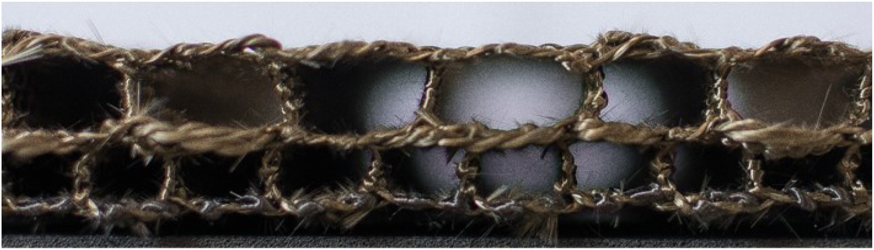
The organizational structure of 3D gradient structured woven fabric are shown in Figure 3. The lines were warped yarn interweaving trajectories, and the circles were weft yarn interweaving trajectories. The blue lines and circles indicated basalt fiber filament yarns, and the black lines and circles told carbon fiber. The picture of the 3D gradient structured woven fabric is shown in Figure 4 and the fabric thickness was 18.5 mm. Organizational structure of 3D gradient structured woven fabric. (1) Warp cross-sectional diagram (2) Organizational chart diagram. Picture of 3D gradient structured woven fabric.
Preparation of 3D gradient structured woven composites
Compared with traditional manufacturing methods, vacuum-assisted resin transfer molding (VARTM) technology has become extensively used in the fabrication of gradient microwave-absorbing composites due to its merits of low cost and high efficiency. In addition, large-scale composite materials can realize automatic mass production through the VARTM process. The vacuum-Assisted Resin Transfer Molding (VARTM) process is shown in Figure 5. The electromagnetic wave absorbing resin was as follows: CB, CIP, and epoxy resin with mass percentages of 1%:45%:54% were mixed and mechanically stirred in a mechanical stirrer for 9 min (Figure 5a). And the resulting resin mixture was ultrasonically dispersed at 75% power for 25 min. The dispersed resin mixture was defoamed under a vacuum for 25 min to cool down and defoam Then add the accelerator with a specified mass ratio (epoxy resin: Accelerator = 1:0.33) to the resin mixture and put it on the magnetic stirrer for 7 min. The obtained solution was vacuumed in a vacuum oven (24°C) for 1 h, the material was shaped at 80°C for 2 h. The process diagram of composite preparation is shown in Figure 5. The dimensions of the specimen are: the upper rectangle is 8.5 mm × 8 mm; the lower rectangle is 6.5 mm × 4 mm; and the overall height is 18.5 mm. Electromagnetic wave absorber manufacturing process and VATRM diagram.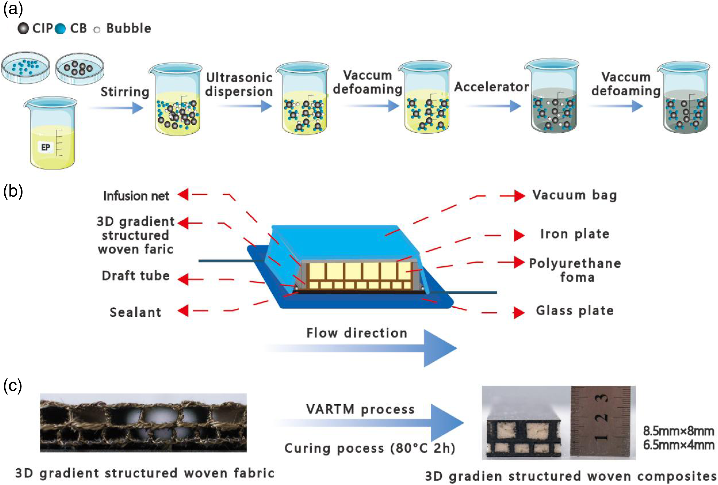
CIP, CB and CB/CIP/epoxy resin microscopic morphology characterization
Figure 6 shows the microscopic morphology of CIP, CB, and CB/CIP/epoxy resin (1%:45%:54% by mass). To observe the smaller size nanoscale CB particles more clearly, TEM was used to characterize the microscopic morphology of CB, as shown in Figure 6a. The CB particles are thin sheets with a particle size of 20–30 nm. The CB particles tend to stack and cluster with each other, which contributes to the formation of conductive chains and conductive networks. According to the SEM images in Figure 6b, the microscopic shape of CIP is approximate “onion head” with particle size between 3 and –5 μm, and the particles form a stacked state. The smooth surface is conducive to the subsequent adsorption and cross-linking with epoxy resin. In the SEM image of Figure 6c, the overall dispersion is good, although a small amount of CIP accumulation appears in the matrix. Due to the aggregation effect of nanomaterials, the nanoscale CB particles in the resin were aggregated into large irregular particles of 10–15 μm, which were uniformly dispersed in the resin. Meanwhile, although a significant accumulation of CB particles occurred, some unagglomerated particles were uniformly dispersed inside the resin that was not observed. In addition, a small amount of debonding occurred between the CIP and the epoxy resin due to external damage during the sample preparation. Micrographs of CIP, CB, and CIP/EP/CB.
Performance test
Electromagnetic wave absorbing properties
The reflection loss test of the 3D gradient structured woven composites was conducted according to the standard GJB 2038-94, as shown in Figure 7, and the incident and returned electromagnetic waves were analyzed by the vector network analyzer. Schematic diagram of bow test system.
Bending properties
As shown in Figure 8, the three-point bending performance of 3D gradient structured woven composites was tested on the TH-8102S servo computerized universal material testing machine (Suzhou Topper Mechanical Equipment Co., Ltd.). According to GB/T 9341-2008/ISO 178:2001, the bending performance of the 3D gradient structured woven composites was tested. Schematic diagram of three-point bending experiment.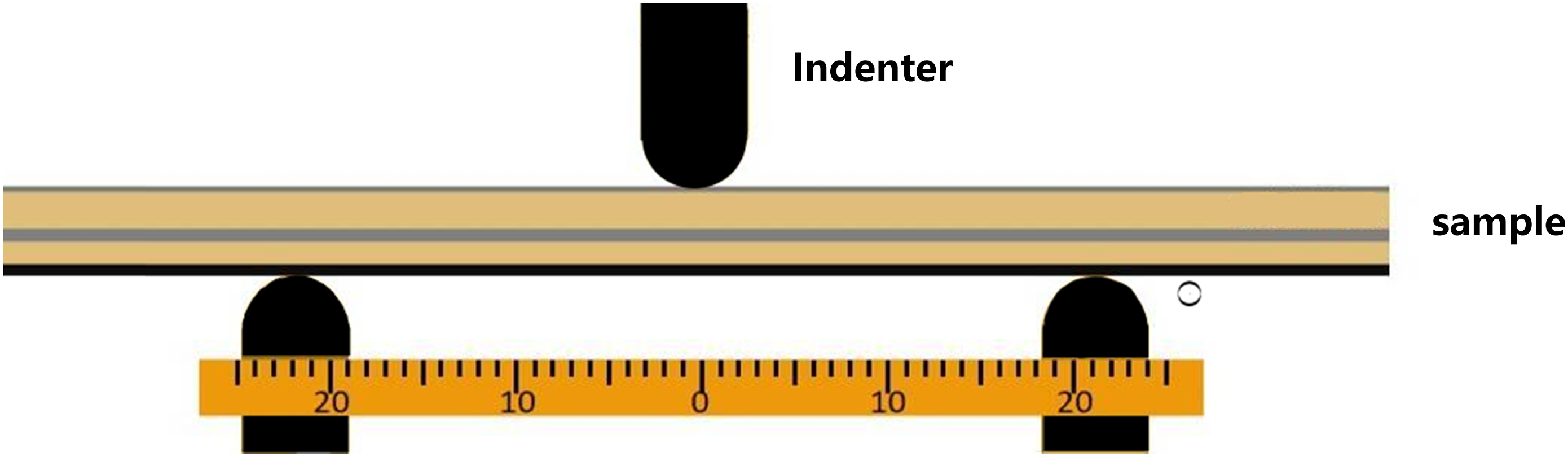
Electromagnetic wave absorbing properties
Modeling
The CST software performed simulations on an 8-core processor, 16 threads, and a 32G memory processor. Basic assumptions: (1) The absorbent is uniformly dispersed in the material, and there are no bubbles in the 3D gradient structured woven composite interior. (2) Ignore the raw material defects in the 3D gradient structured woven composites, i.e., all yarns are intact, the particle size of absorbent is uniform, the material is cracked and porous inside the material, and the material is in ideal condition. It is shown in Figure 9. Boundary condition setting.
Comparative analysis of experimental and simulative results
The experimental and simulative results of the 3D gradient structured woven composites are shown in Figure 10. According to the experimental results, the RLmin of the 3D gradient structured woven composite is −24.4 dB (5.8 GHz), and the EAB was 5.3 GHz (2.2 GHz–2.6 GHz, 5.1 GHz–6.7 GHz, 8.4 GHz–11.7 GHz), and the absorption bandwidth below −5 dB covers almost the whole frequency band from 2 to 18 GHz. The trend of simulative results was similar to the experimental results, but there was a deviation in RLmin. The lowest reflection loss peak points obtained from both experiment and simulation occurred in the C band. However, the lowest reflection loss peak point obtained from the simulation occurred at 6.5 GHz, the lowest reflection loss was −27 dB, the lowest reflection loss obtained from the experiment occurred at 5.8 GHz, and the lowest reflection loss was −24.4 dB. The error value of the peak value was 10.6%. The experimental and simulative values of the 3D gradient structured woven composites had similar curve trends. Here are two reasons for the deviation in the value of the reflection loss, (1) incorrect electromagnetic parameters of the material due to the inhomogeneity of the gradient aperture. (2) In the VARYM process, the irregular movement of the resin leads to the absorbent’s uneven dispersion, which results in the deviation of the reflection loss values. Despite the deviations in experimental and simulation results, it was still a good guide for designing woven composites with 3D gradient structures. Experimental and simulative RL curves.
Analysis of electromagnetic wave absorbing mechanism
The field monitor was set at 6.5 GHz to analyze the mechanism of electromagnetic wave absorption performance of 3D gradient structured woven composites in depth. Figure 11 shows the field distribution of 3D gradient structured woven composite at 6.5 GHz. According to Figure 11, the internal electric and magnetic fields of the 3D gradient structured woven composite showed a horizontal and vertical overlap at 6.5 GHz. According to the numerical distribution, it can be concluded that the magnetic field strength was weaker compared to the electric field strength. The vortex phenomenon existed in the structural layer with a larger aperture diameter. The electric field distribution and magnetic field bottom of the vortex region was relatively dense with better electromagnetic wave loss capability. Combined with the surface current field distribution in Figure 11c, the existence of the eddy current region could be seen more clearly. It can be seen from the current power that the bottom layer of the composite had the highest recent intensity, followed by the middle layer and the lowest current intensity at the surface. This current field distribution confirms that the bottom layer of the material had a high reflection characteristic, and the impedance-matching performance of the surface layer was relatively good compared to the other two layers. Meanwhile, the energy fielded distribution in Figures 11d and e showed that the main effects of the electromagnetic wave loss were electrical and magnetic failures. Among them, the role of electric loss was more pronounced. Distribution of simulated energy field results at 6.5 GHz.
Figure 12 shows the schematic diagram of the electromagnetic wave absorption performance of 3D gradient structured woven composites. The main factors affecting the electromagnetic wave absorption performance of 3D gradient structured woven composites were electrical loss, magnetic loss, and path loss due to the structure. 3D gradient structured woven composites also derive from the synergistic effect of multiple media and unique structural design. Electromagnetic wave absorption mechanism of 3D gradient structured woven composites.
Mechanical property analysis
Modeling
Mechanical property parameters of composite materials.

The simulation parameters for 3D gradient structured woven composites generally include nine constant engineering parameters, mainly elastic and plastic.
The upper surface of the model was constrained to the upper indenter contact surface, and the lower surface was constrained to the two support members. To reduce the computational effort of the model in the actual simulation calculation and to control the displacement motion of the composite model, displacement constraints were applied to the coupling control points of the material. To reduce the computational effort of the model in the actual simulation calculation and to control the displacement motion of the composite model, displacement constraints were applied to the coupling control points of the material. Total fixed constraints U1 = U3 = UR1 = UR2 = UR3 = 0 and U2 = −8 are applied to the lower surface of the model to obtain the composite model with strict boundary condition constraints. The boundary condition constraint diagram of the composite model is shown in Figure 13. Load setting of model.
Number of elements of 3D gradient structured woven composites.

The model meshing diagram of a 3D gradient structured woven composite is shown in Figure 14. Mesh division of 3D gradient structured type woven composite model.
Comparative analysis of experimental and the simulation results
The load-displacement curves of 3D gradient structured woven composites under bending simulation were obtained by finite element simulation of 3D gradient structured woven composites using field output. The load-displacement curves of the experimental and FEM simulations of 3D gradient structured woven composites are shown in Figure 15. Figure 15 shows that the total load obtained from the simulation was 8.311 kN, and the maximum load obtained from the experiment was 8.118 kN, with an error value of 2.37%. The experimental results and simulation results were in good agreement. Load-displacement curves of the experiment and the simulation.
It can be seen from Figure 15 that the bending loaded displacement curve of the simulation and experiment was divided into three stages. In the first stage, the material had no obvious fracture, so the material had good elastic properties, and the curve was linear. In the second stage, the large pore structure was mainly destroyed due to the different pore sizes of the upper and lower layers. Still, the dense structured and carbon fiber filament in the lower layer was not destroyed, so the line segment was still linear, but the slope decreased. In the third stage, the composite continues to bear the load of the upper indenter until it reaches the maximum yield point, and the load-displacement curve will reach the peak value. After that, the composite failure of the material occurs, the whole material is destroyed, and the angle will decrease significantly. The root cause of the error compared to the experimental values is the subjective conditions given during the simulation calculations. This resulted in a more uniform distribution of material components in the simulated composites than in reality, without unexpected states such as uneven resin infiltration and porosity caused by the operation. In the actual bending test experiment, the rough surface of the material causes the indenter to act on the material gradually. In contrast, in the simulation process, the model’s uniform and smooth texture make the upper indenter’s load act on the material evenly from the beginning of loading, resulting in a smoother simulated load-displacement curve. There was no evident decline compared with the experimental data.
Analysis of failure mode and mechanism
Figure 16 shows the finite element simulation failure diagram of the composites; Figure 17 shows the damaged morphology of the 3D gradient structured woven composites. Figure 18 shows the final failure diagram of the experimental test, and Figure 19 shows the stress variation of the composite material deformed during the cyclic loading process. From Figures 16 and 19, it can be seen that the damage mode of 3D gradient structured type woven composites was consistent with the damage mode and mechanism of experimental results. The materials during the bending experiments did not exhibit delamination, which proves that the 3D gradient structured woven composites were highly resistant to delamination and had good integrity. Final failure diagram of finite element simulation. 3D gradient structured woven composites damage morphology diagram. (a) Overall damage pattern diagram. (b) Top damage pattern diagram (c) Side damage pattern diagram (d) Bottom damage pattern diagram. Physical final failure diagram. Stress cloud of composite material at different time.


Since the simulation time during the ABAQUS mechanical simulation was 1 unit duration. Therefore, Figures 19a-h corresponded to the stress program at times 0, 0.14, 0.29, 0.43, 0.51, 0.71, 0.86, and 1, respectively. It can be observed from the figure that the 3D gradient structured woven composite under bending load undergoes deformation damage, and the part in contact with the upper indenter was severely damaged, with stresses spreading from the middle position to the ends of the material.
As can be seen from Figure 16, the 3D gradient woven composite was subjected to a displacement constraint in the opposite direction along the Z-axis. The material was always in the middle of the indenter during the three-point bending test, so the material’s middle position was symmetric, buckling deformation occurred, and the whole material protruded outward. The upper indenter causes a symmetrical distribution of low-stress areas on both sides of the central stress concentration of the material. In contrast, the upper surface of the composite material was subjected to compressive stresses due to the compression of the upper indenter, resulting in downward depression. In contrast, the lower surface was subjected to tensile stresses due to the transfer of load and the load support of the base on the material, resulting in fiber pulling and resin cracking. Comparing the final damage of the actual object in Figures 17 and 18, it can be seen that the upper and lower surfaces were subjected to different loading forms. The surface depression simulated by the finite element method was the depression of the whole structure. In contrast, the dents in the actual experimental samples were mainly concentrated in the contact area of the indenter. The simulation model was ideal, while the solid empirical material is not homogeneous.
The simulations showed that the damage pattern of the composite material was consistent with the damage pattern and mechanism of the experimental results. The simulation results showed that the failure mode and mechanism of the composite were consistent with the experimental results. The material did not show delamination during the bending test, which proved that the 3D gradient structured woven composite had strong delamination resistance and good integrity.
Conclusion
Two-layer 3D gradient structured woven fabrics with rectangular were woven on an ordinary loom with basalt fiber filament yarns and carbon fiber filament yarns as raw materials. The 3D gradient structured woven composites were produced by mixing electromagnetic wave absorbers carbon black and carbonyl iron powder in the resin and using VARTM molding technology.
This paper compares the experimental and simulation results, and the composites’ mechanical properties and electromagnetic wave absorption properties were analyzed. The absorption bandwidth of 3D gradient structured woven composites is below - 5 dB, almost covering the 2–18 GHz full frequency band. The lowest peak point of reflection loss obtained by electromagnetic simulation and experiment is in the C-band. The lowest reflection loss peak point from the simulation is at 6.5 GHz. The lowest reflection loss is −27 dB. The lowest reflection loss peak point from the experiment is at 5.8 GHz. The lowest reflection loss is 24.4 dB. The comparison peak error is 10.6%. In terms of mechanics, the maximum load obtained from the simulation is 8.311 kN, and the full load obtained from the experiment is 8.118 kN, with an error value of 2.37%. The load-displacement curves of the 3D gradient structured woven composite obtained using the general static solver roughly match the experimental curves. Through the finite element simulation analysis, under the bending load, the 3D gradient structured woven composite was deformed and damaged, the contact part with the upper indenter was seriously injured, and the stress spread from the middle to both ends of the material. The damage patterns and mechanisms obtained from mechanical simulations and bending experiments prove that the 3D gradient structured woven composites have good integrity.
This study provides a new 3D gradient structured electromagnetic wave absorbing composite material. The material has good electromagnetic wave absorption performance and mechanical properties, effectively improving the electromagnetic wave absorption performance and integrity of the absorbing material. This article provides a new idea for preparing new gradient-structured electromagnetic wave absorbing composites.
Footnotes
Declaration of conflicting interests
The author(s) declared no potential conflicts of interest with respect to the research, authorship, and/or publication of this article.
Funding
The author(s) disclosed receipt of the following financial support for the research, authorship, and/or publication of this article: This research was funded by the National Science Foundation of Liaoning Province (1645749635925), the Open Project Program of Ministry of Education Key Laboratory for Advanced Textile Composite Materials (Tiangong University), No. MATC-2021-003, the Science and Technology Innovation Foundation (Science and technology benefiting people project) of Dalian (2022JJ13SN099) and Shenghong emergency support and public safety fiber materials and products research project (2022-rw0302).