
Abstract
Abrasive particle-induced erosive wear of polymeric engineering components is a major industrial issue. The research of solid particle erosion characteristics of polymeric composites becomes essential due to operational needs in dusty conditions. Nonwovens are now employed in industrial applications for polymeric composites. Nonwoven products are made from a wide range of raw materials, ranging from synthetic to natural fibers. This work finding the effect of nonwoven cotton fiber (5, 10, and 15 wt.%) loading on the physical, mechanical, and erosion wear of fixed wooden dust (4 wt.%) filled hybrid epoxy composites. Experimental results reveal improved impact strength, hardness, and compressive and tensile strength with an increment of fiber loading from 5–15 wt.%. The density of the composites was found to increase, whereas void content decreases with an increase in cotton fiber. The erosion wear of the composites has been studied using an L27 orthogonal array to assess the effects of various parameters such as fiber loading, erodent size, impact velocity, impingement angle, and stand-off distance. The erosion wear increased with impact velocity and remained highest for 60° of impingement angle. The most significant parameter affecting the erosion wear was determined as impact velocity followed by impingement angle. Surface morphologies of eroded samples reveal the fiber pull-out, and fiber breakage was the prominent phenomenon for the erosion wear of the evaluated composites.
Keywords
Introduction
For decades, composite materials have been used as an alternative to the heavy metals in automobile, space, aircraft, and manufacturing industries.1,2 As per the applications, various composites such as polymer matrix, metal matrix, ceramic matrix, and synthetic and natural fiber reinforced have been used widely.3–6 The last decades have witnessed the development of waste materials and natural fiber–based composites and found remarkable achievements.7–9 Significantly, the development of high‐performance household and industrial products made from natural fibers is increasing worldwide day by day. 10 This is due to the numerous advantages of natural fibers, that is, low cost, reusable, and lightweight, etc. The critical properties of the natural fiber–reinforced composite are biodegradability and renewability, which fulfill the economic interest of composite industries. 11 In this regard, natural fibers, that is, hemp, jute, banana, cotton, sisal, etc., have been successfully utilized as reinforcement by various researchers and scientists.12,13 Cotton fiber is also a natural type of fiber which is used in textile industries for centuries. Dry weather harvested cotton fiber cultivated in the northern and southern hemispheres from the decades. 14 It is also cultivated in various regions of India and has potential use as reinforcement for composites fabrication. Various researchers and scientists potentially used cotton fiber and cotton woven fabric mats to reinforce composites.14–23
P. Sharma et al. 14 fabricated epoxy-based polymer composites reinforced with cotton fiber up to 80 wt.% and conducted mechanical testing such as tensile, flexural, and impact strength. Results reveal that all mechanical properties improve with the addition of cotton fabric. T. Alomayri and I.M. Low 15 synthesis and mechanically characterized the cotton fiber–reinforced geopolymer composites with cotton fiber reinforcement up to 1.0 wt.%. They also examined the fiber dispersion on the mechanical properties of fabricated composites. Experimental results found 0.5wt.% cotton fiber–reinforced composite achieving optimum mechanical properties. T. Alomayri et al. 16 fabricated and investigated the mechanical properties of composites reinforced with different layers of woven cotton fabric with 3.6, 4.5, 6.2, and 8.3 wt.%. Experimental results reveal that all mechanical properties, that is, flexural, impact, flexural modulus, and fracture toughness improved with an increase in woven cotton fabric. M. Taşdemır et al. 17 have used waste cotton fiber and silk as reinforcement to fabricate recycled polycarbonate polymer composites. Composites are fabricated using twin-screw extruded by utilizing waste silk and cotton fiber of length 1 mm, 2.5 mm, and 5 mm. Results show that with the increase in length of silk fibers, yield, tensile, and impact strength decrease, whereas elasticity modulus and hardness are increase. On the other hand, with increasing the length of cotton fibers, hardness, tensile, and yield strength, elasticity modulus decreases, whereas impact strength and percentage elongation increases. G. R. Ioannis 18 studied the effect of cotton fiber in polyester resin. He found that fabricated composite plates can be successfully used for structural parts such as doors. T. Alomayri et al.19,20 fabricated hybrid geopolymer composites with cotton fiber (0.3–1.0 wt.%) as reinforcement and fly ash as filler material. Fracture behavior and mechanical characterization have been done on the fabricated composites. The authors concluded that 0.5 wt.% of cotton fiber gives optimum mechanical properties such as flexural strength and flexural toughness. Moreover, fly ash addition in the matrix phase diminishes the void presents in the composites. S. K. Bajpai et al. 21 discuss the properties of cotton fibers and their reinforcement in various polymer matrices. Results show that fibers should possess good water absorption and this can be achieved through grafting. A. Hebeish et al. 22 modified cotton fibers utilizing conductive coated cotton fabrics with three different nano-cellulose/Polypyrrole substrates. Thermal and mechanical characterization with XRD, SEM, TGA, FTIR, and EDX were studied independently. Authors claimed that the mechanical properties of the fiber are not affected by the chemical treatment, whereas the conductivity of cotton fabric increases. S.A.R. Hashmi et al. 23 studied the sliding wear behavior of ultrahigh molecular weight polyethylene (UHMWPE) modified polyester-cotton–reinforced composites. The author claimed that the 7.41–14.9 vol.% cotton fiber composites exhibit a reduction in specific wear rates.
Nonwoven is a textile fabric mat used in various household applications. Nowadays nonwoven is also used for composites fabrication due to its porous structure. 24 A nonwoven mat is a web structure formed with entangling of fiber in multi directions, and when used as reinforcement it gives more strength to the composites as compared to the aligned fibers.25,26 Various techniques are available to form the nonwoven structure, that is, chemically, thermally, and mechanically. Needle-punched is a type of mechanically bonded technique in which fibers entangling together with needle-punching form a web structure. 27 S. Tejyan et al.25–30 studied the effect of polypropylene, polyester, and viscose fiber–based needle-punched nonwoven fabric mat reinforcement. The authors claimed that the evaluated mechanical properties and erosion wear resistance improved with fabric mat reinforcement.
Various researchers have done a lot of work related to the reinforcement of cotton fiber; cotton fiber–based weaved fabric mat, and synthetic fiber–based nonwoven fabric mat in different matrix materials. They found that cotton fiber, cotton fabric mat, and other nonwoven mats improve physical and mechanical properties if used as reinforcement. In the studied literature, no work was found related to the cotton fiber–based nonwoven fabric mat and wooden dust reinforcement epoxy-based hybrid polymer composites. The objective of this work is to characterize the mechanical and solid particle erosion wear behavior of cotton fiber–based nonwoven fabric mat and industrial waste wooden dust reinforced polymer hybrid composites.
Materials, fabrication, and testing of composites
Matrix material (Epoxy)
Epoxy grade LY-556 (Density: 1.15 g/cm3) with the corresponding hardener, HY 951, supplied by Shankar chemicals and dyers, New Delhi, India is used as matrix material.
Reinforcement material
Black cotton fiber (Density: 1.54 g/cm3)–based needle-punched nonwoven fabric mat (Weight; 400 g/m2, Thickness: 3 mm) as shown in Figure 1a taken as reinforcement material. Moreover, wooden dust (Density: 0.88 g/cm3, Average size: 200 μm) of Sheesham tree as shown in Figure 1b, collected from a local wood cutting Industry, Roorkee, India used as filler material. Wooden dust and fabric mat cleaned and dried for 24 h for the removal of moisture content before use. . (a) Black cotton fiber–based needle-punched nonwoven fabric mat samples. (b) SEM image of cotton fabric mat. (c) Wooden dust.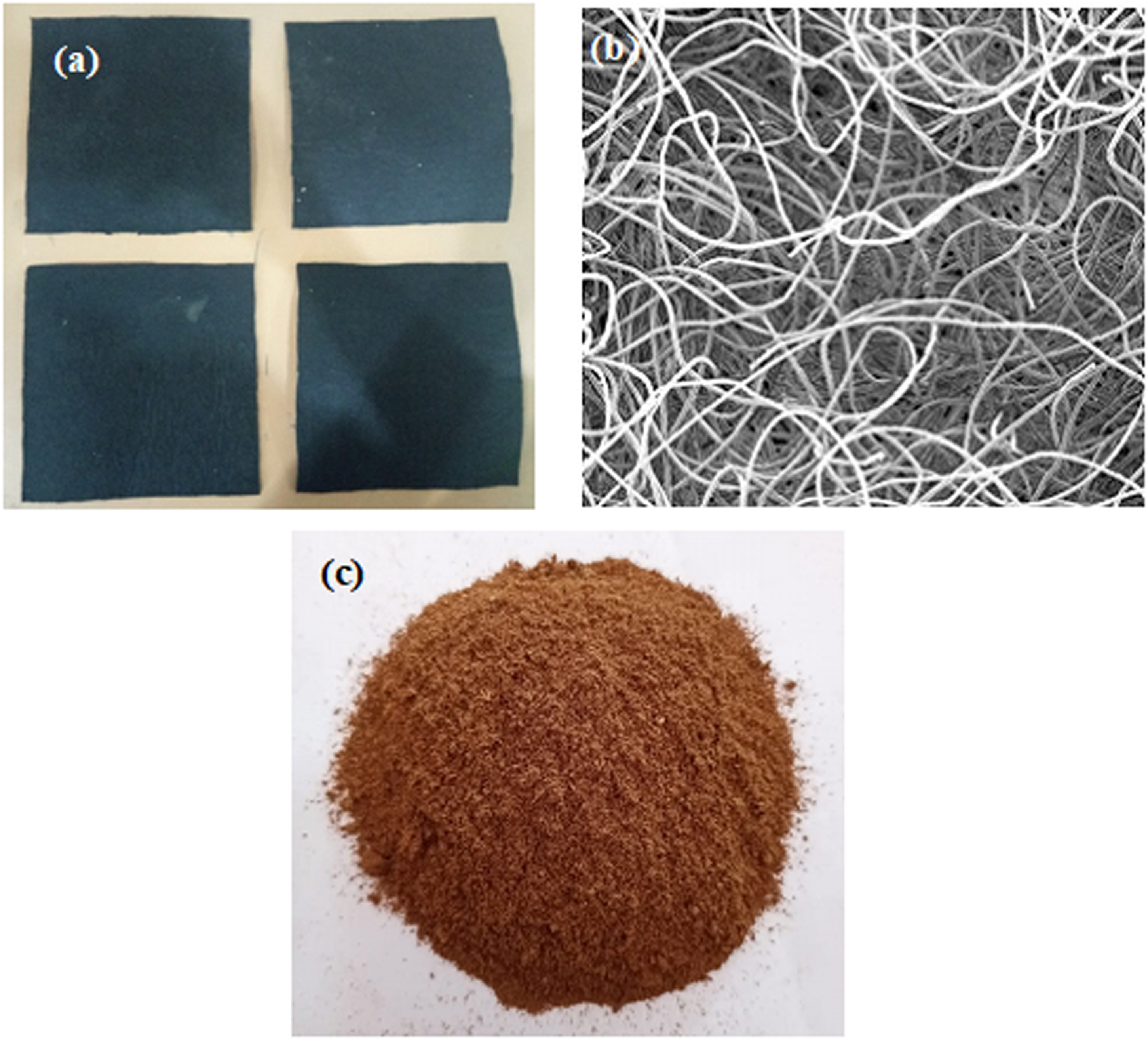
Fabrication of composites
Composition of fabricated composites; CNW1, CNW2, and CNW3.


. (a) Fabrication of composites by hand lay-up process. (b) Curing of composites. (c) Finishing of composites slabs. (d) Cutting. (e) Fabricated composite specimens.
Mechanical characterization
The experimental and theoretical density was measured by simple water immersion technique and rule of mixture, respectively. Whereas the percentage of void content present in fabricated composites was calculated by normalizing the experimental and theoretical density. 32 Composites’ hardness was evaluated by Rockwell hardness tester with B scale as per ASTM E18-20 standards. Impact testing machine (Model no. IT406) from TINIUS OLSEN India Pvt. Ltd was used to evaluate the impact energy of composites as per ASTM D256 standards. Hounsfield test equipment (Model H25K-S) was used to determine the tensile and compressive strength of fabricated composites as per ASTM D3039-76 and ASTM D6641 standards, respectively.
Solid particle erosion
Air jet erosion tester (Schematic diagram: Figure 3a, Model No. 471, DUCOM, India) was used to evaluate the erosive wear rate of CNW1, CNW2, and CNW3 composites at ambient temperature. Erodent particles (Silica sand) of varying sizes (250, 350, and 450 μm) are mixed with dry compressed air in a mixing chamber, further accelerated through a nozzle (Material: Tungsten carbide, internal diameter: 1.5 mm, length: 50 mm) with a constant discharge rate of 10gm/min. These erodent particles impacting the composite specimen of size 30×30 mm2 as shown in Figure 3b prepared as per ASTM-G76 standards. Composite specimens can be held at various angles (30°, 45°, 60°, 75°, and 90°) concerning the impacting particles. The impact velocity of the particles can be varied by varying the pressure of the compressed air, that is, 43, 48, 53, 58, and 65 m/s. Stand-off distance (distance between nozzle output to sample surface) is also varied as 65, 75, and 85 mm using an adjustable sample holder.27,28 Composite samples are eroded in the erosion test rig for 15 min and weighed again to determine the weight loss using the precise electronic weighing machine of Denver Instruments to an accuracy of ±0.01 mg. Composite specimens were cleaned with acetone before and after the test to remove the extra sand particles from the surface. Finally, the erosive wear behavior of CNW1, CNW2, and CNW3 composites have studied through erosion rates (Er), which was calculated by the ratio of the weight loss (mg) to the total mass of the erodent particles (kg) impacted on the specimen surface in 15 min.
29

Taguchi experimental design

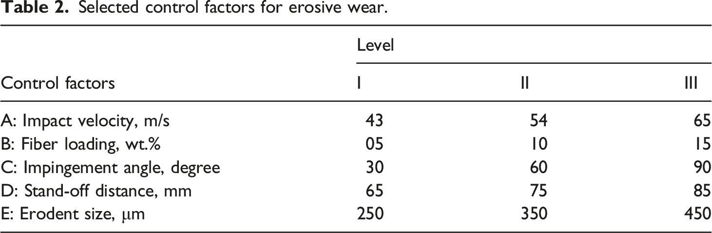
Selected control factors for erosive wear.
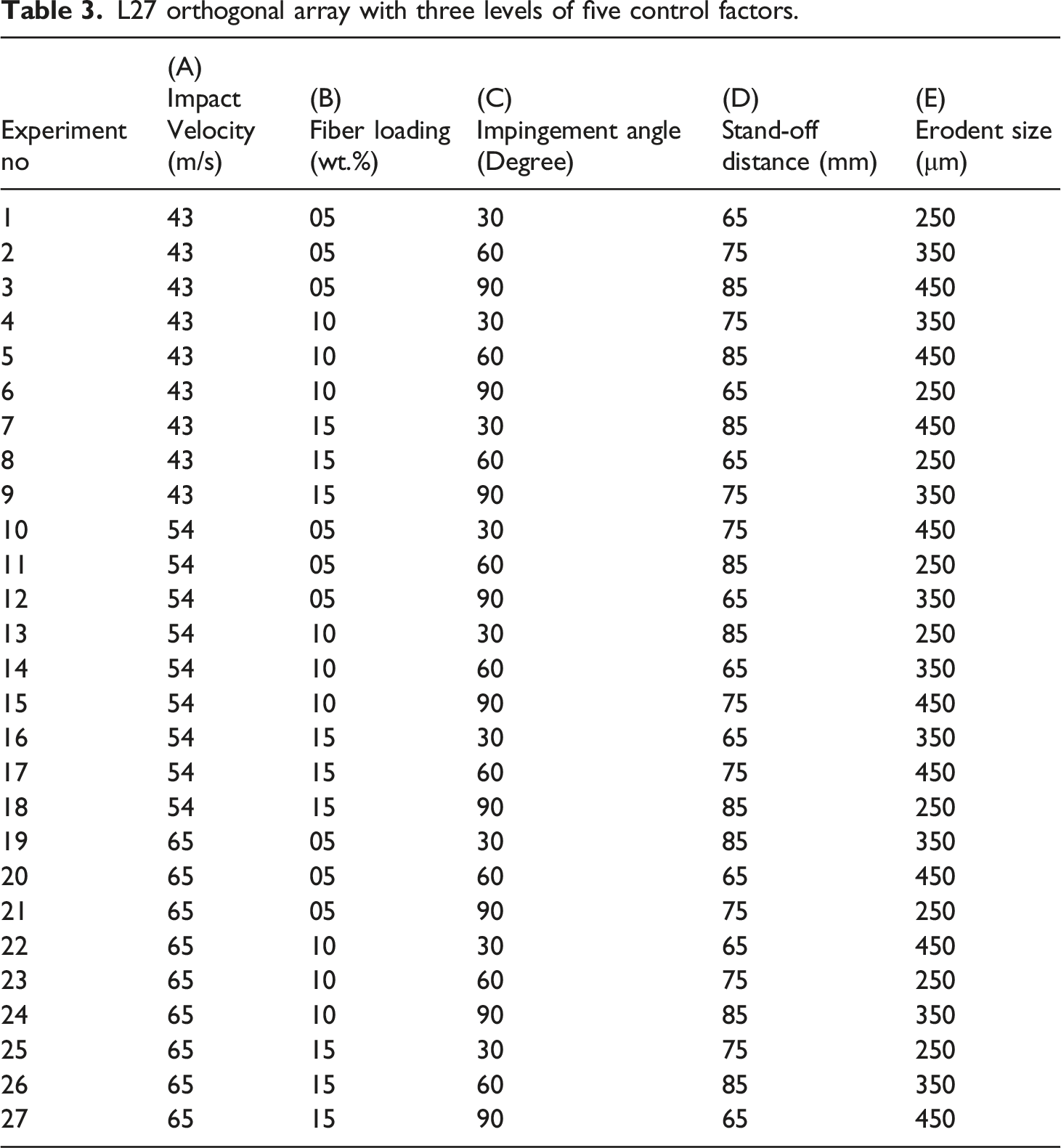
L27 orthogonal array with three levels of five control factors.
Scanning electron microscopy (SEM)
Scanning Electron Microscopy (ZEISS EVO Series, Model No. EVO 50, Oberkochen, Germany) was used to examine the eroded surface of CNW1, CNW2, and CNW3 composites. To avoid the electrostatic charging specimens were coated with gold by bio-radpolaron sputter coater and for the formation of electrically conducting surfaces, colloidal silver paste coating was applied on the investing surface before microscopic image evaluation.
Results and Discussion
Mechanical behavior of fabricated composites
Experimental and theoretical measured densities and calculated void content of the CNW1, CNW2, and CNW3 composites are present in Figure 4. It can be evident from Figure 4 that experimental and theoretical densities are increasing from CNW1 to CNW3 composites. It may due to the increment of weight percentage of higher density material (cotton fiber, density: 1.55 g/cm3) with a fixed amount of low-density material (wooden dust, Density: 0.88 g/cm3) in the epoxy matrix of the density of 1.15 g/cm3.
35
Experimental density is less as compared to theoretical density due to the 0.81%, 0.61%, and 0.42% void presents in CNW1, CNW2, and CNW3 composites, respectively. Voids present in composites decrease may be due to the addition of 4 wt.% of wooden dust with an increasing amount of higher density material, that is, cotton fiber.
35
Figure 5 presents the Rockwell hardness (HRB) and I-zod impact strength for the CNW1, CNW2, and CNW3 composites. Both Rockwell hardness and impact strength improves with the increment of the cotton fiber–based nonwoven mat from 5–15 wt.%. Hardness may increase due to the less amount of void present and impact energy may improve due to the more energy required to break a large number of fibers present in higher weight percentage composites.
36
Similar results for the hardness and impact strength were reported by Tejyan et al.26–29 Theoretical and experimental density of composites with void content. Rockwell hardness on B scale and impact strength of fabricated composites.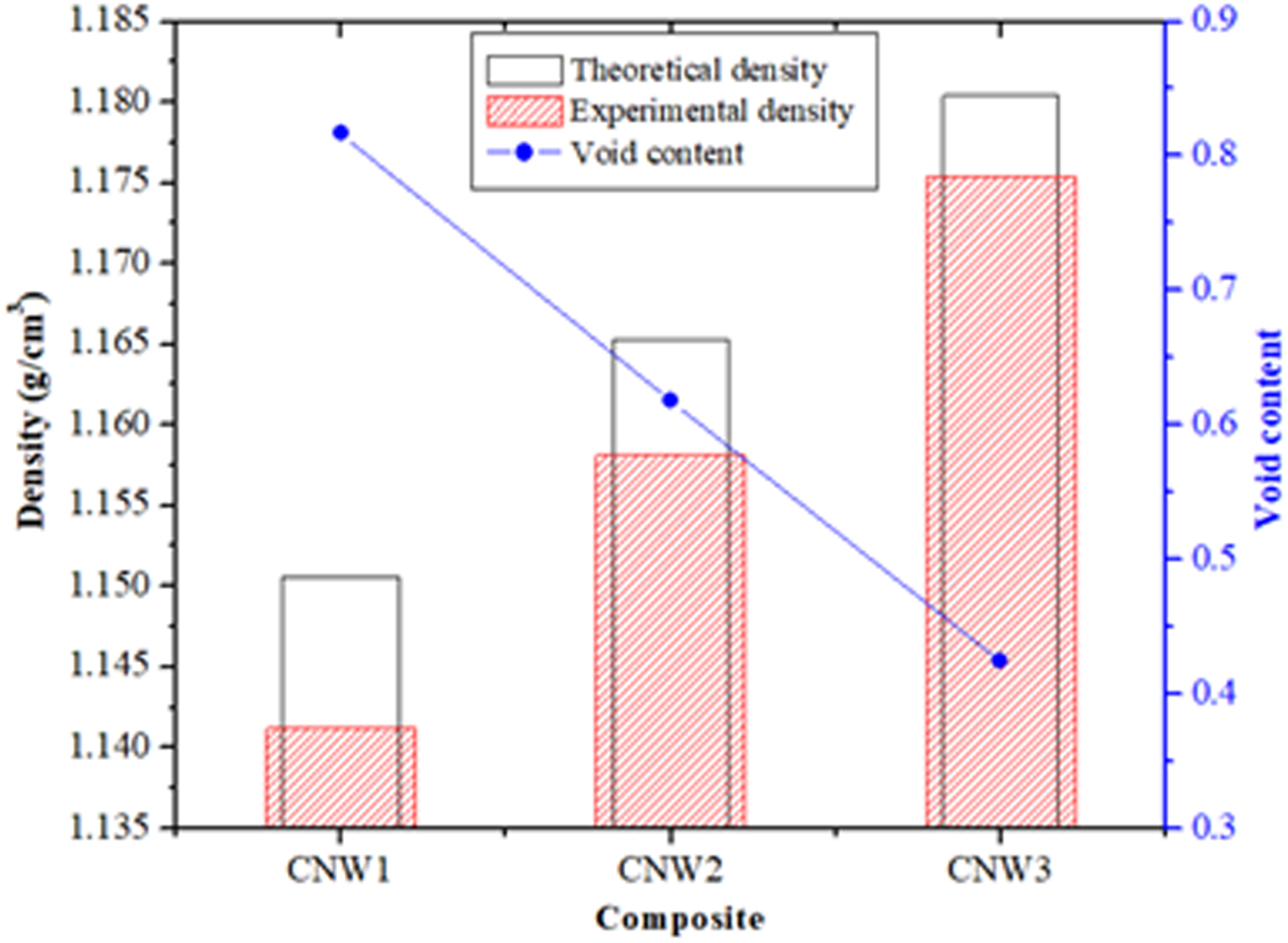

Figure 6 presents the examined tensile and compressive strength for the CNW1, CNW2, and CNW3 composites. Tensile strength increases from CNW1 to CMW3 composites in an order of 43Mpa<52 MPa<58 MPa for CNW1, CNW2, and CNW3 composite, respectively. A similar kind of increment in tensile strength is presented by Patnaik et al.
36
Moreover, Figure 6 also presents the increment in compressive strength from CNW1 to CMW3 composites. It may be due to the brittle behavior of higher percentage composites, and more force is required to break these composites.35–37 The tensile strength of viscose fiber–based needle-punched nonwoven fabric mat reinforced epoxy-based composites varies between 5-22 MPa.
25
For this work tensile strength improves up to 58 MPa, due to the presence of wooden dust as filler material. Tensile and compressive strength of fabricated composites.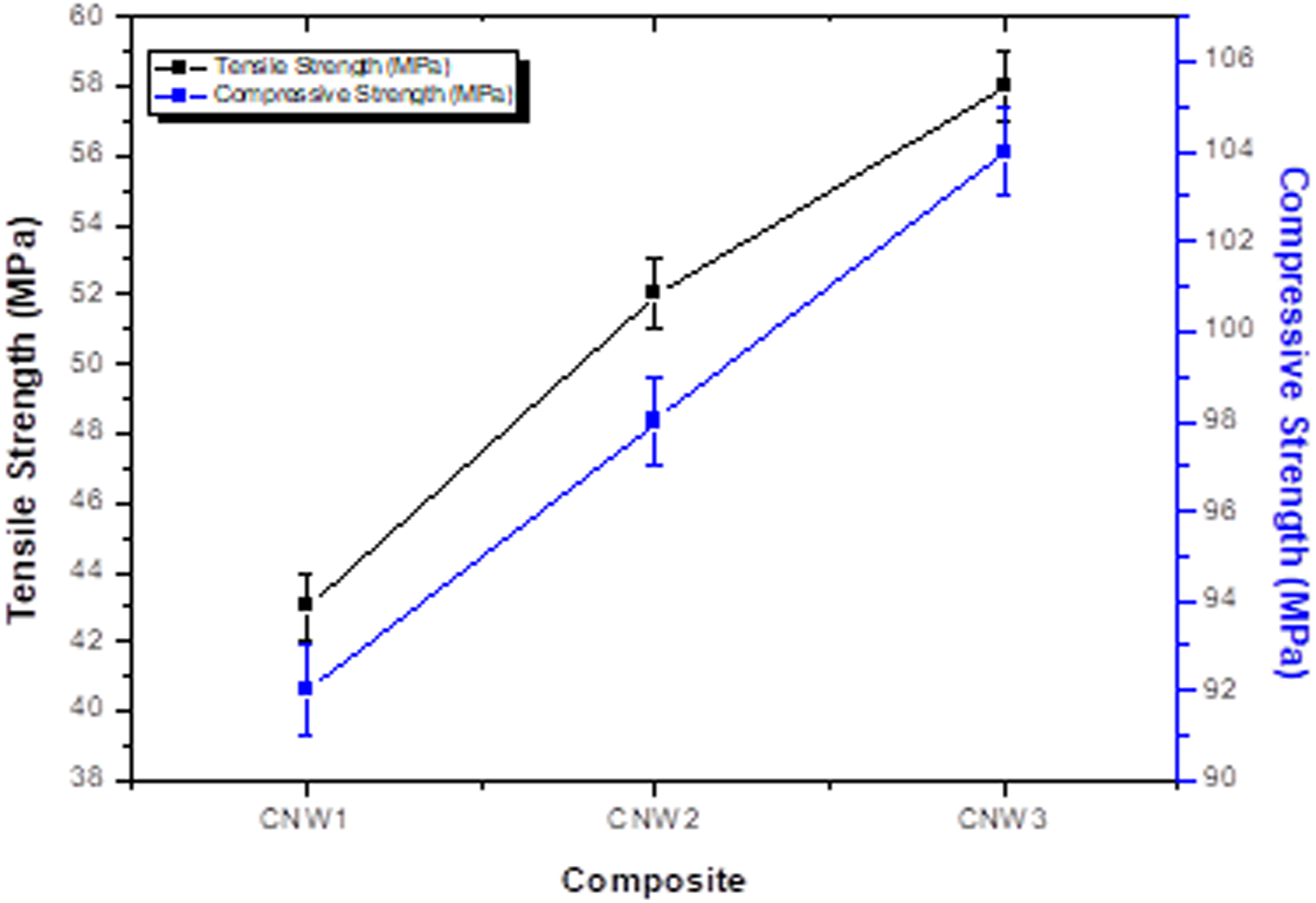
Influence of impingement angle and impact velocity on erosion wear
Erosive wear rate with varying impact velocity (A) for the composites, that is, CNW1, CNW2, and CNW3 is present in Figure 7. Other control factors such as impingement angle (C), stand-off distance (D), and erodent size (E) are kept constant as 60°, 75 mm, and 350 μm, respectively. The erosion rates of the fabricated composites are increasing in an order of CNW2<CNW1<CNW3 as shown in Figure 7. Among all the fabricated composites CNW2 shows the lowest erosion rate. It may be due to the optimal weight percentage of cotton fabric mat (10 wt.%), wooden dust (04 wt.%), and epoxy resin (86 wt.%) as compared to other composites CNW1 and CNW2. Another phenomenon, that is, erosion rate of composites increasing with the increase of impact velocity is also present in Figure 7, which may be due to the higher kinetic energy of the impacted erosive particles.38–40 Erosive wear rates of composites with varying impact velocity, and constant impingement angle (60°), stand-off distance (75 mm), and erodent size (350 μm).
Figure 8 shows the erosive response of cotton nonwoven fabric mat reinforced composites with varying impingement angles. Other control factors, that is, impact velocity (A), stand-off distance (D), and erodent size (E) are kept constant as 53 m/s, 75 mm, and 350 μm, respectively. Among all the composites, the CNW3 composite shows the highest erosion rate at all selected impingement angles. It may due to a large number of ductile fibers present in the epoxy matrix. Similar results were also represented by Tejyan et al.24–27 Moreover, all composites, that is, CNW1, CNW2, and CNW3 present the highest erosion rate at 60° impingement angle. This presents the semi-ductile nature of composites.37,38 Erosive wear rates of composites with varying impingement angle, and constant impact velocity (53 m/s), stand-off distance (75 mm), and erodent size (350 μm).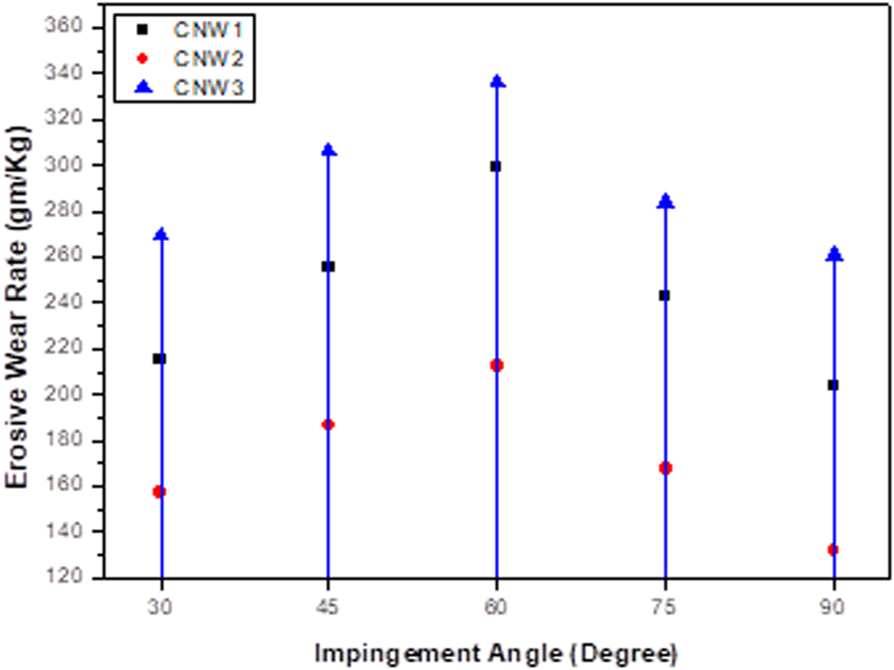
Taguchi analysis of experimental results for fabricated composites
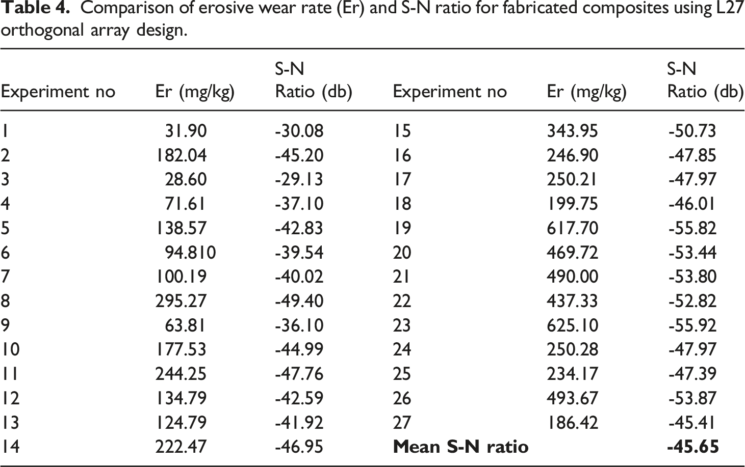
Comparison of erosive wear rate (Er) and S-N ratio for fabricated composites using L27 orthogonal array design.

Effect of control factors on the erosive wear rate of CNW1, CNW2, and CNW3 composites.
Analysis of Variance (ANOVA) table for the selected control parameters.

Figure 10 presents the interaction graphs between A: Impact velocity, B: Fiber Loading, and C: Impingement angle. Factor combination of A×C and B×C shows that impingement angle of 60° gives minimum SN ratio value, which gives minimum erosion rate. Similarly factor combination of A×B gives minimum erosion rate at 5 wt.% fiber loading and 65 m/s impact velocity. Interaction graph between A×B, B×C, and A×C for the erosive wear rate of composite.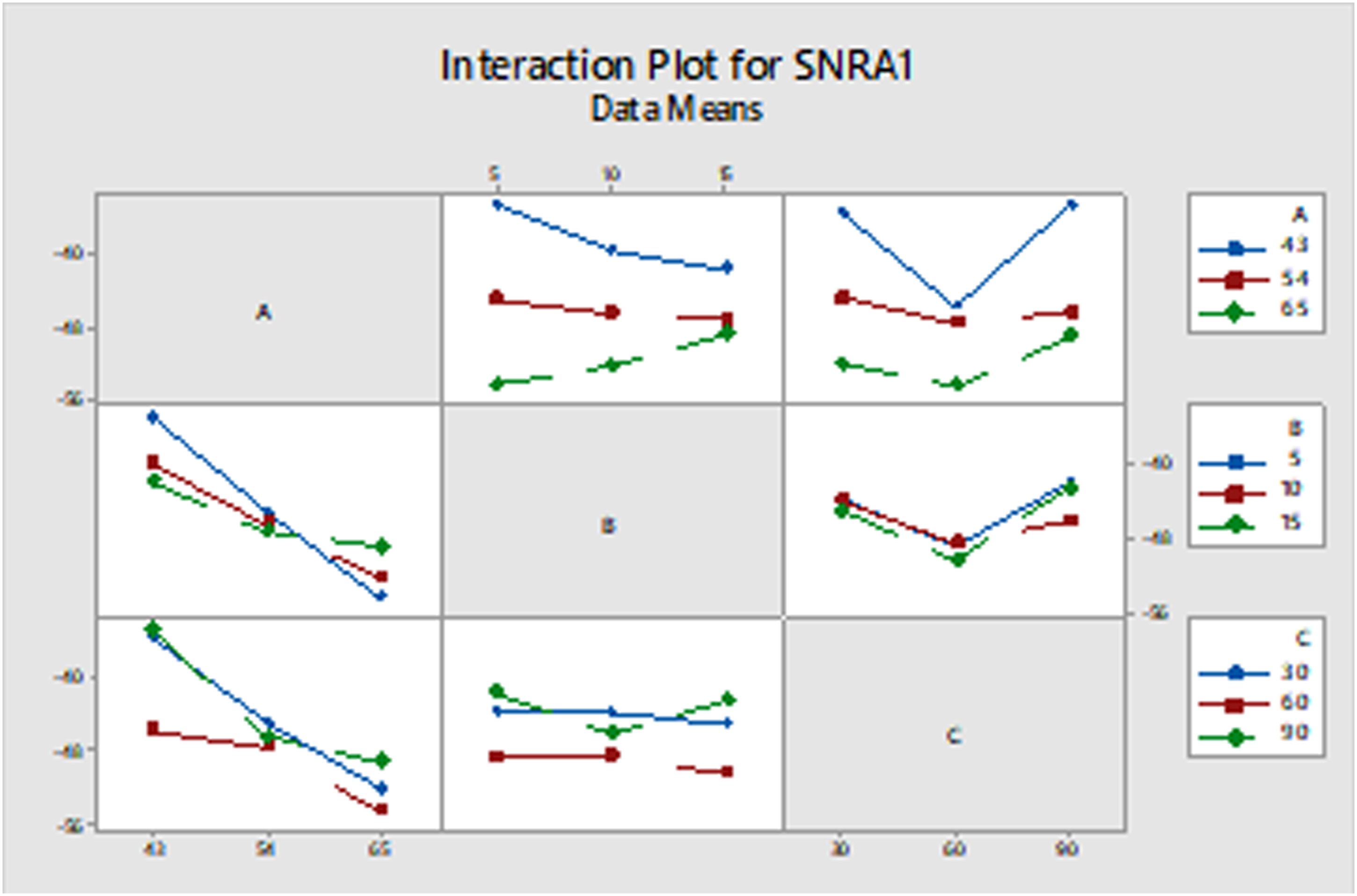
Surface morphology of eroded composite samples
To characterize the effective wear mechanisms and to identify the mode of material removal, the surface morphology of eroded surfaces of CNW1, CNW2, and CNW3 composites were observed under a Scanning Electron Microscopy (SEM). Figure 11 presents the micrographs of the eroded surfaces of composites. In this work, the highest erosion rates of CNW1, CNW2, and CNW3 composites come at a 45° impingement angle. It may due to the ductile nature of cotton fibers, cotton fiber-based nonwoven fabric mat, and wood dust and brittle nature of epoxy matrix.
38
This brittle and ductile nature of matrix and reinforcement makes CNW1, CNW2, and CNW3 composites more sensitive to the impact energy of silica sand (erodent). This phenomenon of composites erosion rate at 45° of impingement angle explains the semi-ductile nature of the CNW1, CNW2, and CNW3 composites.
40
Figures 11(a) and (b) show the micrographs for the CNW1 composite surface which is eroded at low impact velocity (43 m/s), at medium stand-off distance (75 mm), and impingement angle (60°). It shows exposure of wooden dust particles and cracks formation: Figure 11a, and local removal cotton fiber from the impacted surface: Figure 11b.
41
The micrograph in Figure 11b also shows that due to the impact of sand particles on fibers there is micro-plowing and breakage of fibers.
42
The micrographs of the CNW2 composite surfaces are shown in Figure 11c. The surface of the CNW2 composite is eroded at an impingement angle of 60 with a low impact velocity of 43 m/s, 75 mm stand-off distance, and 450 μm erodent size. Figure 11c shows the propagation of fiber pulling and large crack formation.41,42 Moreover, exposure and breaking of cotton fibers are more prominent as present in Figure 11d for the CNW3 composite. Surface morphology of eroded composite samples.
Conclusions
Composites were fabricated successfully by simple hand lay-up technique utilizing cotton fiber–based needle-punched nonwoven reinforcement, wooden dust as a filler material, and epoxy as a matrix. Mechanical and erosive wear behavior of fabricated composites has been studied and found these conclusions. The density of the CNW1, CNW2, and CNW3 composites increasing with the increase of cotton nonwoven fabric mat may be due to a higher weight percentage of cotton fiber. Void contents in the CNW1, CNW2, and CNW3 composites are very less, that is, 0.81%, 0.61%, and 0.42%, respectively, due to the wooden dust filler content present in composites. Mechanical properties such as hardness, impact strength, compressive, and tensile strength present the improvement in the order of CNW1<CNW2<CNW3. Erosion rates for CNW1, CNW2, and CNW3 composites are increasing with the increase of impact velocity. In comparison, the erosion rate of CNW1, CNW2, and CNW3 composites are higher at 45°, which shows the semi-ductile nature of fabricated composites. The ANOVA analysis clearly shows that impact velocity (A) has the highest effect on the erosion rate of composites. All selected control factors show the effect on the erosion wear rate in the order of Impact velocity (A) > Impingement angle (C) > Stand-off Distance (D) > Fiber Loading (B) > Erodent Size (E). The micrograph of the eroded samples reveals that fiber pull-out and fiber breakage are the main phenomena for the erosive wear of the CNW1, CNW2, and CNW3 composites.
Footnotes
Declaration of conflicting interests
The author(s) declared no potential conflicts of interest with respect to the research, authorship, and/or publication of this article.
Funding
The author(s) received no financial support for the research, authorship, and/or publication of this article.