
Abstract
Using a lapped seam, PVC-coated hybrid textiles with uniform thickness were bonded by continuous ultrasonic welding and conventional joining method with the help of hot air tape welding technique for weather protection purposes. Three fundamental sewing parameters at two distinct levels and three primary welding parameters at three levels based on 6 and 12 mm welding widths were used. To consider the effect of welding and sewing parameters on seam strength, full factorial designs of experiments were designed, fabricated, and tested. The thermal behavior and possibility of chemical conversion in the welding zone under the influence of ultrasonic vibrations were examined. Variation in width of heat-affected zone of weld seam was measured. The seam strength of ultrasonic weld seam compared with that of conventional seams, and superior seam strength yielding parametric levels were assessed. The parametric influence of both joining techniques on seam quality and their tendencies in the relationship were analyzed statistically. The weld seam strength (1256.392 and 2116.93 N/50 mm) was optimized numerically and identified its trend with the variation of the weld seam. The discovered relationship led to the conclusion that the variation in the weld seam can be used to estimate the tensile strength of the weld seam through the developed effective numerical model as a non-destructive testing method, and its outcome was successful as a destructive testing method. The result shows that the ultrasonic weld seam provided a higher tensile strength ( > 75%) than the conventional seam for both evaluated welding widths and obtained statistically significant results.
Keywords
Introduction
Conventional sewing is the most popular method of joining fabrics despite such disadvantages as discontinuous joints producing perforated seams, sewing thread deteriorating with time, and sewing speed limitation.1-3 The majority of textile products consist of more than one component joined together through sewing.3,4 For continuous assembly without a perforated stitch, other sewing methods should be required.3,5 Thermal bonding, laser enhanced bonding, adhesive bonding, and ultrasonic seaming methods are performed through melting and cooling the joined thermoplastic surface.1,3,6 Gutnik et al. 7 have reported that the thermoplastic material is the most suitable material for ultrasonic seaming joining as well as ultrasonic seaming is an effective and efficient method to assemble two or more thermoplastic materials through high-frequency vibration without polymer degradation.1,3,8 Ultrasonic seaming has wide application areas including the application in the automotive industry, medical and hygienic products, sports, work and protective wear, covering and packaging, underwear, filters, and technical textiles.1,3,9
Ultrasonic sealing provides many benefits as an alternative to joining together fabrics made of thermoplastic polymer containing a significant amount of thermoplastic content. This technique requires no needles, solvents, adhesives, mechanical fasteners, or other consumables that reduce costs.1,3,10,11 Flood 3,11,12 have noted the fiber degradation that was minimized due to the generation of heat energy within the fibers using ultrasonic energy at the point of the joint site, unlike thermal bonding where heat energy was conducted through the fibers to melt them. Energy-saving, the possibility of precise automated assembly using computer-aided manufacturing technology are the additional benefits of ultrasonic bonding, and the recycling of the product is relatively easy since foreign yarns are not used to produce seam.1,3,10,11 Another advantage is achieving an impermeable seam for technical textile applications such as aircraft and clothing for contaminated environments 1,3,9-11 as well as roof cover and tent for weather protection purposes.
The development of plastics and their composites has opened new doors for extensive research. 13 A significant number of researches have made using ultrasonic welding because of its advantages afforded by its clean, fast, and reliable approach for thermoplastic joining process.3,10,11 Ahmed et al. 14 have also reported that joining is a critical step in the process of manufacturing thermoplastic composite products. Due to these, the effects of welding speed and seam sealing speed were studied on the physical properties of seamed fabrics, but the impact of amplitude and roller pressure of ultrasonic welding parameters were not reported in the research made by Na et al. 15 To get a proper understanding of ultrasonic welding and vibration welding, Wu et al.13,16 implemented the design of an experiment on polyolefin and have investigated that the amplitude of vibrations is a dominant factor for weld strength in both welding processes. Rani et al.13,17 also applied fractional factorial design to the ultrasonic welding of acrylonitrile butadiene styrene and high-density polyethylene and found that the welding time and pressure were significantly affected the joint strength. Subhas and Renuka3,18 investigated the effects of welding pressure and time on bond strength and examined the bond location at the interface based on the image of scanning electron microscopy and temperature measurement. They found adequate seam strength under some sealing conditions for polyester and spectra fabrics using continuous and discontinuous ultrasonic welding machines.
Mahmut 1 analyzed the tensile property of ultrasonic seam based on polypropylene, polyester, and polyamide/polyester blend of thermal bonded nonwoven fabrics to investigate the effect of the ultrasonic seam, fiber type, fabric area density, and bonding surface on ultrasonic seam strength and elongation at break properties. Tsujino et al.13,19,20 studied the welding characteristics of ultrasonic welding systems based on 20, 40, and 67 kHz frequency levels and achieved a larger value of weld strength using 67 kHz welding equipment. Subhas and Renuka 3 have stated that a poor energy transmission takes place at lower pressure force; consequently, the fabric temperature was not raised to the required level as well as the fiber orientation was not maintained. Shi and Little 6 investigated the effects of three important welding parameters (weld pressure, time, and amplitude of vibration) on joint strength and placement of optic fibers into the fabrics using ultrasonic welding to build a smart seam. They found that the weld strength increased initially with increasing weld pressure (up to 30 psi), but further increased pressure caused a decrease in the strength. The same effect was also observed in changing weld time and its critical value was 2.5 s. 6 Mahmut 1 stated that ultrasonic seam tensile strength increased in a way parallel to the increase in fabric area density for all fabrics used in his study, and the rollers were effective in ultrasonic seam tensile strength in a way parallel to the increase in the sewn surface. Subhas and Renuka 3 reported that the fabric temperature was raised when a certain amount of ultrasonic energy was applied under pressure. This temperature created sufficient mobility for the molecular chains to slide within the crystalline regions and to form the rows of weld points between the fabrics layers. Thus, it caused spot welding rather than surface melting and melt bonding.
As Wu et al.13,16 investigated the higher weld strength for ultrasonic welding than that of the vibration welding in the case of polyolefin, the maximum weld strength (40% of the base material strength) was obtained by utilizing ultrasonic welding and 66% was attained by employing vibration welding. Mahmut 1 has reported that the polypropylene fabric has the highest seam tensile strength and ultrasonic sewing is an effective method for assembling nonwoven fabrics. A high ratio of polyamide affected the ultrasonic seam strength negatively. 1 Subhas and Renuka 3 investigated a higher seam efficiency for polyester fabric than that of spectra fabric. Wu et al.13,21 employed an ultrasonic welding technique for welding plastic with various geometries and proposed a certain welding time with a high level of normal pressure that was used to achieve higher weld strength.
Using woven and nonwoven fabrics, Boz and Erdogan1,9 were compared the ultrasonic sewing with that of double pressure sewing. Mistik et al.1,8 also compared the tensile properties of ultrasonic, lock, and chain sewing methods using woven fabric and the result showed that the ultrasonic seam tensile properties were lower than that of lock and chain sewing methods. 8 In another study, it was stated that the use of polypropylene-polypropylene and polyester–polyester fabrics achieved better bonding. 6 Although sewing-thermo adhesive tape sealing has been widely used in outdoor applications, it has a quality problem resulted from a needle hole and thread such as seam leaking and excess shrinkage.22,23 Due to these, the ultrasonic welding-thermo adhesive tape sealing method was developed for joining waterproof fabrics in outdoor applications. This method can avoid the deficiency of sewing-thermo adhesive tape sealing and ultrasonic welding technology by reducing shrinkage in the ultrasonic welding process and improving the seam strength in the thermo adhesive tape sealing process. 22 Hui et al. 18 have investigated the mechanical property of the ultrasonic welding seam that is weaker than the sewing-thermo adhesive tape sealing seam. Previous studies have presented the ultrasonic welding machine roller surface shape and seam type that plays a vital role in the decision of seam mechanical properties.9,11,24
Shi and Little 6 studied the heating and bonding mechanisms of the ultrasonic welding process on nylon/cotton, cotton, polyester, and Nomex fabrics with and without polyurethane adhesives. They have explored that the strongest weld was obtained in the lightweight fabric of battle dress uniform with polyurethane film at welding conditions of weld pressure 30 psi, weld time 2.5 s, and amplitude of vibrations 60 μm. Joint strength with polyurethane film had much higher strength than without polyurethane adhesives under the same weld condition. 6 Hui et al. 18 further compared the waterproof, dimensional stability, and mechanical performance of seam produced by ultrasonic welding-thermo adhesive tape sealing with that of ultrasonic welding seam and sewing-thermo adhesive tape sealing seam. They have also studied the influence of ultrasonic welding parameters on ultrasonic welding-thermo adhesive tape sealing seam performance and proved that continuous ultrasonic welding is the most perspective method to produce a qualitative reliable joint of fabrics. 18 Thus, this method can replace traditional needle-thread sewing technology in the garment industry and make the use of this technology more attractive in the outdoor application of industrially produced textiles, 18 but further study is still required for outdoor technical applications as well as many issues associated with machine parameters setting and operation.
Many studies have been conducted experimentally to search the optimal welding condition and effect of welding parameters on joint strength using a plunge mode of operation. Those studies are used to ensure the joining quality that relies on welding system configuration and welding parameter specification. However, very few works of literature were focused on the quality of weld seam for technical applications. Thus, it limits the use of continuous ultrasonic welding technology in textiles. Even the current literature pays particular attention to a few ultrasonic welding factors and almost little attention to the welding width of the anvil wheel and their effective heat-affected zone. An empirical investigation in different welding widths of anvil wheel, changes in the width of heat-affected zone of the weld seam, and considerations of all probable welding factors are necessary to find out the effect of these factors on bond strength. These may result in significant improvement in the bond strength. Moreover, destructive techniques are widely used practice for estimating the joining quality of weld seam, but non-destructive techniques are more attractive as a rapid quality testing method for estimating the joint strength based on the width of the heat-affected zone in the weld seam. Therefore, discovering the relationship between them leads to the development of an effective numerical model to predict the tensile strength in a non-destructive way. Furthermore, the combination of the microstructure of ultrasonically welded hybrid textiles in terms of chemical and thermal characteristics and the effect of welding width of the heat-affected zone in weld seam strength have never been studied before on hybrid textiles for any technical applications including weather protection. Hence, it gives a direct picture of joint development in ultrasonic welding of fabrics.
Based on these gaps, the present study is used to examine the variation of the weld seam and their relation/trend with tensile strength in ultrasonic welding of PVC-coated hybrid textile using lapped joint configuration. Through which the correlation and potential of weld seam variation as a joining quality estimator are investigated by formulating an alternative numerical model for weld strength. Three important welding process parameters (welding pressure, time, and power) with two different welding widths are used to investigate the effects on joint strength based on a specific material that is commonly used for weather protection purposes as a trial. The parametric effect of ultrasonic welding and conventional joining techniques on seam performance and their propensities within the relations are therefore established. For both joining techniques, prevalent seam strength yielding parametric levels of hybrid textile is measured to substantially optimize the bond strength numerically. Furthermore, the paper examines the melting behavior of hybrid textile when ultrasonic energy is applied to study the nature of heat evolution (thermal profiles at the interface) and is used to study the possibility of chemical conversion of hybrid textile in the welding zone under the influence of ultrasonic vibrations. The materials, methods, and machines selected for this research are explained following the study of the state of the art. Various observations based on the results are analyzed and objectively reported on the discussion part at distinct speeds. The findings of this study will enlighten the potential of ultrasonic technology for the outdoor application of industrially produced textiles in weather protection.
Experimental
Materials
Mechanical property of hybrid textile material. 27

Physical property of hybrid textile material. 27

The thickness and width of transparent seam seal tape (Brand: Trans-Textil GmbH, Model: LOUP 22,130 two-ply) was 0.13 and 22 mm, respectively. The seam seal tape has a melting temperature of 110°C and a washing temperature of 40°C. The total weight of the seam seal tape is 207 g/m2, considering the film weight of 130 g/m2 and the substrate weight of 77 g/cm2. The tape is made of a double film PE-PU with PE substrate, which is different from the coating film on the woven fabric. The seam tape was welded on the face of the coating side of the woven fabric. The seam tape was customized according to the material property and the manufacturer recommendation of 3.5 bar of roller pressure, 0.5 bar of hot air pressure, 2 m/min of welding speed, and 350°C of welding temperature with a roller position of silicone on the top side and steal below (S-S). To ensure an appropriate softening point, a bit higher melting temperature of PVC (150°C) is significant in face of the coating side of woven fabric than the seam tape (110°C) during hot air welding. The thickness of the coating of the woven fabric is similar to the seam tape. The temperature and extensibility of the hybrid textile material are matched with the seam tape because the polyurethane base seam tape has excellent bond strength when ultrasonically bonded6,28 and its softening temperature is close to that of the coating material.
Fabrication of seam
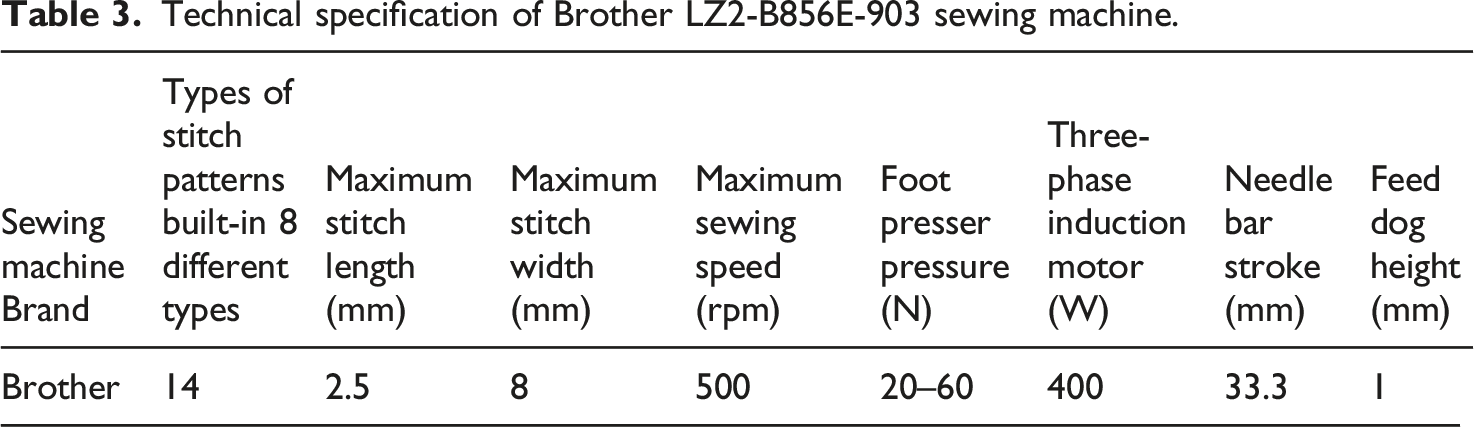
Technical specification of Brother LZ2-B856E-903 sewing machine.
The weld seam was produced by a new generation continuous ultrasonic welding machine called NUCLEUS ROTOSONIC DX1 shown in Figure 1(a) from NUCLEUS GmbH Company in Germany. It used titanium sonotrode with a maximum width of 12 mm at different anvil wheel welding widths (3, 6, or 12 mm) depending on the selected type of anvil wheel and welding width. The main operating screen, an integrated multi-touch screen of 11 inches, displays the following features: ultrasonic welding parameters (including power (5–1000 W), speed (1–21.4 m/min), pressure force (6–510 N), type of anvil wheel (depending on the pattern/engraving), and anvil diameter (40 or 65 mm)); features (including anvil-differential in speed-offset (%), puller in differential (%), offset arm down (mm) and offset arm up (mm), and gap-control in gap-height (mm)); and analyzer (including speed (m/min), power (W), power-target (W), amplitude (μm), frequency (Hz), arm-position (mm), and pressure force (N)). The value of the welding process parameters is changed by touching the touch screen; thus, the welding progress can be changed and programmed through the touch screen. It supports USB ports to export required data during welding after the machine is powered on. Nucleus roto-sonic DX1 ultrasonic machine (a), diagram of continuous ultrasonic welding technique (b), forming mechanism of ultrasonic weld seam (c).
The working principle of the continuous ultrasonic welding machine is shown in Figure 1(b). The ultrasonic power supply (1) converts the low-frequency line voltage of 50 Hz, reversible to 60 Hz by the ultrasonic generator (NUCLEUS Digital Generator of DG1 1000 W), into a high frequency of electrical energy of 35 kHz. This frequency of ultrasound is scarcely audible to the human ear. The downstream equipment transducer/converter KR35-1200 (2) converts the electrical energy into mechanical vibrations with the same frequency. The mechanical vibrations are transmitted to the acoustic transformer/booster IP51 (3). It ensures that the noiseless amplitude of the converter (2) is optimally adjusted to the sonotrode/waveguide (4). The sonotrode (4) oscillates at 35 kHz frequency and 28 μm amplitude against the anvil wheel (5) and deliveries to the hybrid textile materials (6 and 7). Heat is generated by molecular and boundary surface friction. In the uniting region, the substance begins to molecularly soften and forms a sound barrier due to the plasticized and heavily damped plastic sheet, resulting in a very intense melting of the plastic. The reaction accelerates automatically, as an increasing proportion of the vibration energy, and is converted into heat. The simultaneous pressure exerted by the anvil wheel (5) lowering unit reinforces the welded connection in the weld metal/working table (9). By using a post-press puller, the seam attachment can be further improved (contact pressure up to 5 bar). The machine can also cut and weld the material by anvil wheel (5) at the same time or only can weld at a time depending on the selected type of anvil wheel.
The process of the conventional joining technique was carried out in two steps as shown in Figure 5(a). First, the flexible hybrid textile material was sewn in zigzag stitches for eight different combinations considering the stitch pattern, stitch length, and stitch width as sewing factors with two different levels. The selected levels were 2 and 3 for the stitch pattern, 2 and 2.5 mm for stitch length, and 4 and 8 mm for stitch width at an average speed of 20 cm/sec based on the preliminary experimental study on the material. In the second step, the seam seal tape was bonded following the thread track (welded exactly in the middle of the seam) by sealing machine using the hot air welding technique, and during welding puckering of the membrane is avoided. The process of hot air welding compresses and blows air through electrical heat elements to add heat at the welding point and inject it. Following, as a second step, the hot air welding parameters were set at: hot air temperature of 350°C, welding speed of 2 m/min, welding pressure of 3.5 bar, and hot air blowing pressure of 0.5 bar with 55 L/min air consumption at 30 mm nozzle width. Finally, the welded tape was calendared at a welding speed of 2 m/min and a pressure of 3.5 bar between welding wheels to ensure proper bonding in the hot air tape sealing machine.
There was only one welding step in the process of the ultrasonic welding technique as shown in Figure 5(b). Ultrasonic welding was performed for 6 and 12 mm welding widths of the anvil wheel. A flat or plain anvil wheel with a 65 mm diameter was used considering the application area of the material. Welding power, speed, and pressure forces were independent variables (welding parameters) for this research. The levels of each welding parameter were set based on the preliminary experimental investigation on the hybrid textile material. The working range of welding power (40–100 W), speed (1–3 m/min), and pressure force (40–300 N) were investigated for anvil wheel welding width of 6 mm, whereas the welding power (60–120 W), speed (1–3 m/min), and pressure force (40–350 N) were investigated for anvil wheel welding width of 12 mm. The selected levels as per the preliminary experiments are shown in Figure 2 by considering three factors at three levels for welding widths of 6 and 12 mm. 33 full factorial design of experiments (a) to show the effect of anvil wheel welding widths for 6 and 12 mm, (b) to show the effect of welding power for 12 mm, (c) to show the effect of welding pressure force for 12 mm, and (d) to show the combined effect of welding power and pressure for 12 mm welding width.
27

Seam types of the two processes are shown in Figure 3. The specimen was 300 mm in length and 50 mm in width. But the seam length was 250 mm (because five specimens were prepared at a time) and the seam width is shown in Figure 3(a) for conventional seam and Figure 3(b) for weld seam. Outside is the face side that will be exposed to the external environment, whereas the inside is the back side of coated hybrid textile material that will be exposed to the internal environment of the selected application area. During welding, a suitable type of lapped seam was produced by placing 15 mm edges of one textile material on the top of another,
29
which exceeded the width of the anvil wheel. Diagram of seam type for conventional joining technique at 4 and 8 mm stitch widths (a), ultrasonic welding technique at 6 and 12 mm welding widths of the anvil wheel (b).
Evaluation of process efficiency
Yang
30
reported that methods of time measurement (MTM) could be used to decide the optimal method and to evaluate the process efficiency by setting a time quota. The time measurement unit (TMU) is usually used to express the MTM time value (1TMU = 0.036 s). MTM implies that, as shown in the following equation, a certain working process time depends on the implemented method.
31


Seam strength test
One of the most important factors for outdoor technical application is seam durability. Tensile strength was chosen to characterize seam durability because it could be used to evaluate the joined behavior between adjacent hybrid textile material and the welding performance between hybrid textile material and tape. The tensile strength of the seam was tested under testing climatic conditions at a temperature of 20 ± 2°C and 65 ± 4% relative humidity according to DIN EN ISO 139 standard, and compared among the two processes in this study. The tensile strength of conventional and ultrasonic weld samples was tested on the Zwick/Roell-Zmart-Pro strip tensile testing machine with a rate of extension (constant testing speed) of 100 mm/min and a gauge length of 200 mm according to DIN EN ISO 13,935-1 standard. As per the testing standards, the samples were cut into the size of 250 mm x 300 mm in width and length, respectively, and subsequently sewn or welded in a weft direction.
32
Then the sewn or welded samples were cut into five different 50 mm width samples. In such a position that the seam line was in the center of the gauge length, the prepared sample was clamped. It reported the required maximum force to rupture the seam perpendicular to the extension direction. Observation should be made to make sure that the seam failure was due to rupture not due to fabric tears. If the fabric breaks, the results should not be used, and the test should be repeated for another sample. Usually, more than five samples were prepared for contingency. Thereby, the seams rupture at the seam line due to tape and sewing thread breakage or due to ultrasonic bond breakage were only considered in the research. Furthermore, the tensile strength seam performance evaluations were expressed by using seam efficiency because seam efficiency taking into account the factors of material or fabric strength and seam strength simultaneously. Seam efficiency can be calculated using equation (3) as Subhas and Renuka 3,4,33 mentioned.

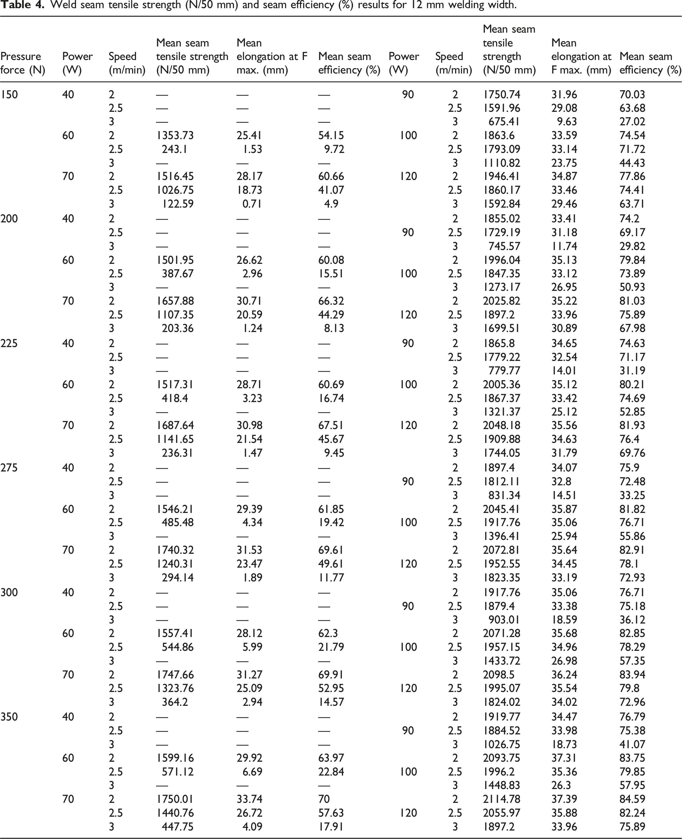
Weld seam tensile strength (N/50 mm) and seam efficiency (%) results for 12 mm welding width.
Conventional seam tensile strength (N/50 mm) and seam efficiency (%) results.

Evaluation of weld seam variation
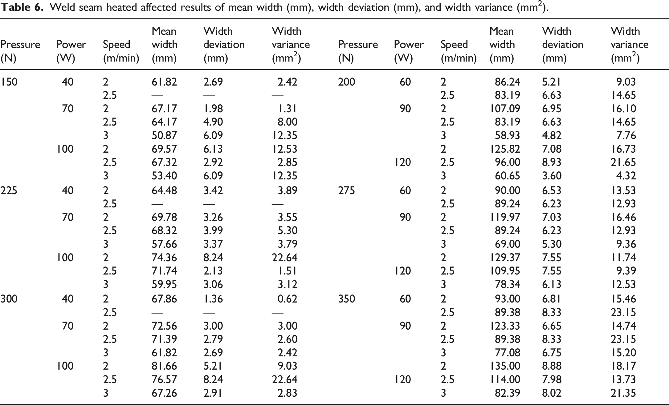
The width of the weld seam and depth of penetration are the most important factors that determine the welding seam quality. The width on the bottom side of the weld seam is the direct physical parameter reflecting the depth of penetration. However, in practice, it is not easy to inspect the width on the bottom side of the weld seam directly when the thickness and the number of layers are large. Estimating the width of the bottom side weld seam was reported according to the shape of the top side weld seam. For this reason, this paper had investigated the variation in the width of the top side weld seam to estimate weld seam tensile strength using a welding combination of pressure force (150, 225, and 300 N), power (40, 70, and 100 W), and speed (2, 2.5, and 3 m/min) for 6 mm welding width of anvil wheel, and pressure force (200, 275, and 350 N), power (60, 90, and 120 W), and speed (2, 2.5, and 3 m/min) for 12 mm welding width of anvil wheel. To estimate the variation of the weld seam, firstly a series of magnified pictures of the top side of the weld seam was taken section-wise by Leica Microsystems using colored CCD Digital Microscope Camera at 80x total magnification power. As the length of the top side of the weld seam was approximately 50 mm and the overall field of view of the microscope was 5060 μm x 5060 μm, 10 weld seam patch images were captured for each welding combination, as shown in Figure 4, to create panorama images of the top side of the weld seams. Then the top side of the weld seam image was imported into CATIA V5 to extract the two boundary curves of the top side of the weld seam efficiently. Finally, the variation in the width of the top side of the weld seam was measured through the deviation analysis between the two extracted curves. The result of the mean and variation of the width of each weld seam combination is summarized and presented in Table 6 for 6 and 12 mm anvil widths. The width of the weld seam and its variation are listed with corresponding welding process parameters of pressure force, power, and speed. Extracted boundaries of heated affected welding width of the top side weld seam. Weld seam heated affected results of mean width (mm), width deviation (mm), and width variance (mm2).
Chemical analysis
Fourier transform infrared spectroscopy (FT-IR) test was performed to study the possibility of the chemical conversion of the polymer in the weld zone under the influence of ultrasonic vibrations. Because the test determines the functional groups and other chemical compositions from different fibers and polymers by IR transmission peak, as well as identifies organic materials, new components, and foreign materials, and surface contamination on the materials, and additives in the polymer. The hybrid textile material was examined before and after ultrasonic welding and their spectra were compared. The tests were carried out on PerkinElmer FT-IR Spectrometer (Spectrum Two) over a spectral range of 4000 to 400 cm−1 at a resolution of 4 cm−1 after fixing the sample holder until the force gauge was obtained between 10 and 20 N.
Thermal analysis
Differential Scanning Calorimetry (DSC) test was also used to study the melting behavior (analysis of the thermal behavior of the ultrasonically sealed material) of the thermoplastics hybrid textile material when ultrasonic energy was applied. 0.0278 and 0.0246 g of untreated and treated sample weight were used for the test, respectively. The test was carried out using a PerkinElmer DSC 4000 series testing instrument based on the heating rate of 20°C/min with the initial temperature of 30°C and final temperature of 445°C at 2.0 bar starting from zero mW initial heat flow for determination of glass transition, crystallization, and melting temperature of the polymer for all tests.
Statistical analysis
ANOVA analysis of weld seam tensile strength (F max. in N/50 mm) for 6 and 12 mm welding widths.

Coefficients analysis of weld seam tensile strength (N/50 mm) for 6 and 12 mm welding widths.

Results and discussions
Process efficiency evaluation
Concerning equation (1), the MTM time of three method units were 34.72 TMU (T1, Sew unit), 208.61 TMU (T2, Seam sealing unit), and 166.67 TMU (T3, Ultrasonic welding unit), respectively. The results were T Conventional Joining Technique = T Sewing + T Seam Sealing = T1 + T2 = 243.33 TMU and T Ultrasonic Welding Technique = T Ultrasonic Welding = T3 = 166.67 TMU. Hui et al.
18
reported the MTM time of the new joining method produced by combining ultrasonic welding with a seam sealing method for an outdoor garment. In this process, two separate and continuous steps are shown in Figure 5(c) by joining the samples with ultrasonic welding before sealing the tape through the hot air welding technique. As Hui et al.
18
have been investigated in their research, the MTM time of this new process is more than the counterpart of the conventional joining technique; the thread-less seam formed in this process is superior to the conventional joining method in the economy of materials, reduction of garment weight, and novel appearance. The MTM time of this new joining method was evaluated for our research purpose and found about T New Joining Technique = T Ultrasonic Welding + T Seam Sealing = T3 + T2 = 375.28 TMU. Thus, it would be necessary to suggest a comparison of process efficiency with the other two techniques, but it requires further study to compare their seam performance by setting the parameters as the same as those in ultrasonic welding and seam sealing methods. The result was the T New Joining Technique > T Conventional Joining Technique > T Ultrasonic Welding Technique since the average speed of ultrasonic welding (4.17 cm/sec) was less than that of the sewing (20 cm/sec). Therefore, the average speed of ultrasonic welding should be increased to improve the process efficiency of ultrasonic welding and new joining techniques in the industrial production of outdoor products for technical applications as well. Process flow of conventional joining technique (a), ultrasonic welding technique (b), and new joining techniques (c).
Seam strength of the two processes
Weld seam tensile strength as a function of welding pressure force and power at different welding speeds of 2, 2.5, and 3 m/min is plotted for anvil wheel welding width of 12 mm in Figures 6(a)–(c), respectively. To investigate the effect of ultrasonic welding parameters and anvil wheel welding width on tensile strength of weld seam, different experiments were carried out on hybrid textile material with different welding combinations and present their tabulated result in Figure 6. It can be inferred from the plot that the weld seam tensile strength ranged from 1353.73 to 2114.78 N/50 mm, 243.10 to 2055.97 N/50 mm, and 122.59 to 1897.20 N/50 mm at welding speeds of 2, 2.5, and 3 m/min shown in Figures 6(a)–(c), respectively. The minimum tensile strength value (122.59 N/50 mm) of the bond was obtained for the experimental combination used to demonstrate the effect of anvil wheel welding width at the lowest welding pressure force (150 N), a medium welding power (70 W), and the highest welding speed (3 m/min) according to Figure 6(c). In contrast, the maximum tensile strength value (2114.78 N/50 mm) was found for the experimental combination used to investigate the combined effect of welding power and pressure force at the highest welding pressure force (350 N), the highest welding power (120 W), and the lowest welding speed (2 m/min), cf. Figure 6(a). Weld seam tensile strength (N/50 mm) of 12 mm welding width at 2 (a), 2.5 (b), and 3 (c) m/min welding speeds.
The tensile strength of conventional seam as a function of stitch length (2 and 2.5 mm) and stitch width (4 and 8 mm) at different stitch patterns (2 and 3) are plotted in Figures 7(a) and (b), respectively. To investigate the effect of sewing parameters (stitch pattern, stitch length, and stitch width) on tensile strength of conventional seam and compare the result with that of the weld seam, these experiments were carried out on hybrid textile material using a zigzag stitch and represent their tabulated result in Figure 7. It can be inferred from the plot that the tensile strength of conventional seam ranged from 233.00 to 274.87 N/50 mm at a stitch pattern of 2 and 235.95–290.56 N/50 mm at a stitch pattern of 3. The maximum tensile strength of conventional seam (290.56 N/50 mm) was obtained based on a stitch width of 4 mm, stitch pattern 3, and a stitch length of 2 mm, cf. Figure 7(a), whereas the minimum value (233.00 N/50 mm) resulted from a stitch width of 8 mm, stitch pattern 2, and a stitch length of 2.5 mm, cf. Figure 7(b). Tensile strength of a conventional seam (N/50 mm) at 2 (a) and 3 (b) stitch patterns.
The maximum value of weld seam tensile strength showed an increment of up to 727.83, 707.59, and 652.95% for welding width of 12 mm, and 428.91, 378.84, and 349.12% for welding width of 6 mm at welding speeds of 2, 2.5, and 3 m/min, respectively, compared to the maximum conventional seam strength of 290.56 N/50 mm. Except for the highest welding speed of 3 m/min, the minimum value of weld seam tensile strength for 12 mm welding width showed an increment of up to 581.00 and 104.34% at welding speeds of two and 2.5 m/min, respectively, compared to the minimum conventional seam strength of 233.00 N/50 mm. This was different in the case of the 6 mm welding width, where the minimum value showed an increment of up to 282.12, 408.31, and 399.45% for all welding speeds of 2, 2.5, and 3 m/min, respectively. The tensile strength of the conventional seam was lower than that of the ultrasonic weld seam based on a 6 and 12 mm welding width of anvil wheel. Because the tensile force was mainly influenced either by the joining force between fabrics and seam sealing tape in case of a conventional seam or the bonding force between fabrics in case of an ultrasonic weld seam; although the conventional seam had joining force (due to sewing thread) and bonding force (due to seam sealing tape), the bonding force between fabrics (due to ultrasonic energy) created a higher influence on the tensile force of weld seam. According to these results, it can be concluded that the bonding force of ultrasonic weld seam, based on a 6 and 12 mm welding width and optimally selected parameters, caused a much higher tensile force than the joining force and seam sealing tape in a conventional seam; hence, the ultrasonic welding technique can successfully replace the traditional joining technique. Furthermore, the result fulfilled not only the test methods but also the requirements of camping tents mentioned for weather protection purposes on ISO 5912:2020 standards.
Since seam efficiency is the ratio of seam strength to fabric strength, it can define the capacity of the material itself to carry a seam, and the durability of the seam can be determined in terms of seam efficiency. Seam efficiencies of 60–80% are common, but efficiencies between 80 and 90% are more difficult to obtain.4,33 The weld seam efficiency was obtained from 54.15 to 84.59%, 9.72 to 82.24%, and 4.90 to 75.89% at welding speeds of 2, 2.5, and 3 m/min, respectively. However, the weld seam efficiency was below 85% for all welding speeds while the conventional seam efficiency was below 15%, which was found from 9.32 to 10.99% and 9.44 to 11.62% at stitch patterns of 2 and 3, respectively. A lower value of seam efficiency was observed on the conventional seam and a similar observation was reported by Subhas and Renuka 3 while studying the ultrasonic sealing of polyester and spectra fabrics. These results indicated that the sewn hybrid textile material had been damaged during the sewing operation (during penetration of the needle and sewing thread) due to fiber dislocation in the fabric, which caused a reduction in fabric strength. The conventional seam efficiency also depends on seam sealing and seam fastness. Considering these, the seam fastness should be improved by enhancing the sewing thread rather than changing the tape to attain higher conventional seam strength. The seam efficiency is also further dependent on the seam type, stitch density, needle type, and size as well.
The failure location of the test sample was observed for conventional seam and ultrasonic weld seam during the seam strength test to make sure that the seam failure was due to rupture not due to fabric tear. As Niromi and Darron 11 identified, there were three main reasons for seam failure in the sewing method, namely, failure due to thread breakages, fabric breakage, and a combination of thread and fabric breakage; whereas, the specimens with polyurethane films were also failed due to fabric damage, bond damage, and a combination of fabric and bond damage. 6 Based on these observations, all of the conventional seam ruptures were observed at the seam line due to tape and sewing thread breakages. Besides, the ultrasonic weld seam failure was also occurred in three modes due to bond breakage, fabric breakage, and a combination of fabric and bond breakage. The first mode of failure is desirable because it indicates that the seam is strong and flexible, and most of the weld seam rupture was observed at the seam line due to ultrasonic bond breakage. The tensile load obtained here is, therefore, more indicative of the strength of the fabric. However, few weld samples were showed that the fabric was broken but not the seam. This is because the hybrid textile material has a lower tensile strength compared to the seam on such welding combinations. In other words, the load to break the fabric with the seam is higher than the load need to break only the fabric and this gives a percentage of seam efficiency more than 100%.
Effects of ultrasonic weld parameters on seam strength
Welding pressure force
As the welding pressure force increased from 150 to 350 N, the tensile strength of the weld seam slightly increased by 15.40, 40.32, and 265.72% at 70 W welding power, and 12.35, 11.33, and 30.43% at 100 W welding power for welding speeds of 2, 2.5, and 3 m/min as shown in Figures 8(a)–(c), respectively; an exception to this rule was presented by the lowest welding power of 40 W. These results showed that the welding pressure force had a lower positive effect on tensile strength of weld seam. Since the welding pressure force was applied to ensure energy transmission and bonding between the fabric surfaces, the effect of horn cross-section on the sample at the location of horn became deeper as the welding pressure force increased, which created hot compaction that affected the bonding between the fabric layers. At the higher pressure force of the horn, the polymer kinematic viscosity increased, which attributed to the reduction of free volume due to packing,
3
hence the hot compaction caused the material to deform after welding. Dissipated friction also increased once the welding pressure force was increased and caused a higher plastic dissipation due to thermal softening. Due to these factors, the effect of welding pressure force on the tensile strength of the weld seam was less as a result of decreasing the transfer of ultrasonic vibration. However, a positive effect of welding pressure force was observed on the tensile strength of the weld seam as the welding pressure force increased. Weld seam tensile strength (N/50 mm) as a function of pressure force (N) for 12 mm welding width.
Weld seam tensile strength improved initially and then began to increase slightly within the optimal working range of welding pressure force of the material because most of the original coating material and fiber properties can be retained during hot compaction of the fabric under optimum conditions. 34 A similar observation was reported 34 under sufficient pressure, the fibers were restrained from shrinking and losing orientation consequently, retained the fiber strength and promoted a strong bond. The observation was also supported by research 3,6,35-37 according to which the seam strength increased with increasing weld pressure; however, strength tended to decrease at very high pressure and weld energy. Although greater welding pressure forces additionally improve the acoustic contact and effective strain during the process, 35 it orients the polymer chains during ultrasonic welding and decreases the weld strength.36,37 For too greater welding pressure forces, the horn displacement was nearly reached to the value of doubled sealing layer thickness (which means nearly a complete expulsion of the sealing layer) and caused a significantly enhanced temperature rise in the welding zone, which led to material accumulation (deformation) or damage at the seam side due to an extreme melt flow .6,35,38 Thus, the sealing pressure force influenced the melt flow effectively during the process within the optimal working range 35 since a too high-pressure force associated with uncontrolled melt flow that reduced the thickness. Shi and Little 6 have also reported that a minimum pressure is required to produce satisfactory welds.
Due to a higher penetration, on the other hand, a relatively pronounced changing effect of welding pressure force was achieved on weld seam tensile strength for welding power of 70 W at welding speeds of 2.5 and 3 m/min with rising pressure force. Based on the analyzed results, it can be concluded that the changing effect of welding pressure force on weld seam tensile strength decreased once the welding power was altered from 70 to 100 W for all welding speeds. In other words, a higher change was attained at a welding power of 70 W compared to the higher welding power of 100 W for all welding speeds. However, the changing effect of welding pressure force increased when the welding speed was improved from 2 to 3 m/min for all welding pressure forces. Thus, the increase in strength due to higher welding speed was greatly influenced by the welding pressure force. Figures 8(a)–(c) illustrates that the weld seam tensile strength as a function of welding pressure force of 150, 200, 225, 275, 300, and 350 N at different anvil wheel welding speeds of 2, 2.5, and 3 m/min in the forward direction is plotted for different welding powers of 40, 70 and 100 W.
Welding Power
When the welding power increased from 40 to 120 W, the tensile strength of the weld seam drastically increased by 43.78, 665.19, and 1199.32% at 150 N welding pressure force, 34.99, 356.47, and 638.04% at 225 N welding pressure force, and 34.74, 266.16, and 400.83% at 300 N welding pressure force for welding speeds of 2, 2.5, and 3 m/min shown in Figures 9(a)–(c), respectively; exceptions are the lowest welding power (40 W) for welding speeds of 2 and 2.5 m/min, cf. Figure 9(a) and (b), and welding power (40 and 60 W) for a welding speed of 3 m/min, cf. Figure 9(c). The results showed that the welding power strongly and positively affected the tensile strength of the weld seam because welding power affected the amount of energy that was transferred into the welding area, which strongly affected the dissipated energy during welding. When the ultrasonic energy was applied to the thermoplastic material, the temperature increased and caused the polymer to melt or partially melt at that location depending on the transferred energy; consequently, intermolecular diffusion occurred between the two layers of the fabric followed by recrystallization and new bond formation.
3
As Shi and Little
6
described, the joint strength was determined by the degree of fusion, which was mainly dependent upon the temperature at the interface. Thus, the rate of temperature rise increased with increasing power that strongly affected the bonding strength, and welding strength correlated with the thermal energy at the interface. Hence, energy input increased with increasing welding power, but a further increase in energy input inversely affected the bond strength. This observation was supported by research
35
according to which a greater welding power led to more intensive heat generation in the interface, which resulted in a decrease in strength of the weld seam. A similar observation was also made by research 6,39 that further increasing the energy input were decreased the strength by 15%. A higher welding power together with pressure force tended to decrease the thickness, which led to a decrease in seam strength. Therefore, the energy dissipation and strength were enhanced once the welding power increased within the optimal working range of the material. Weld seam tensile strength (N/50 mm) as a function of power (W) for 12 mm welding width.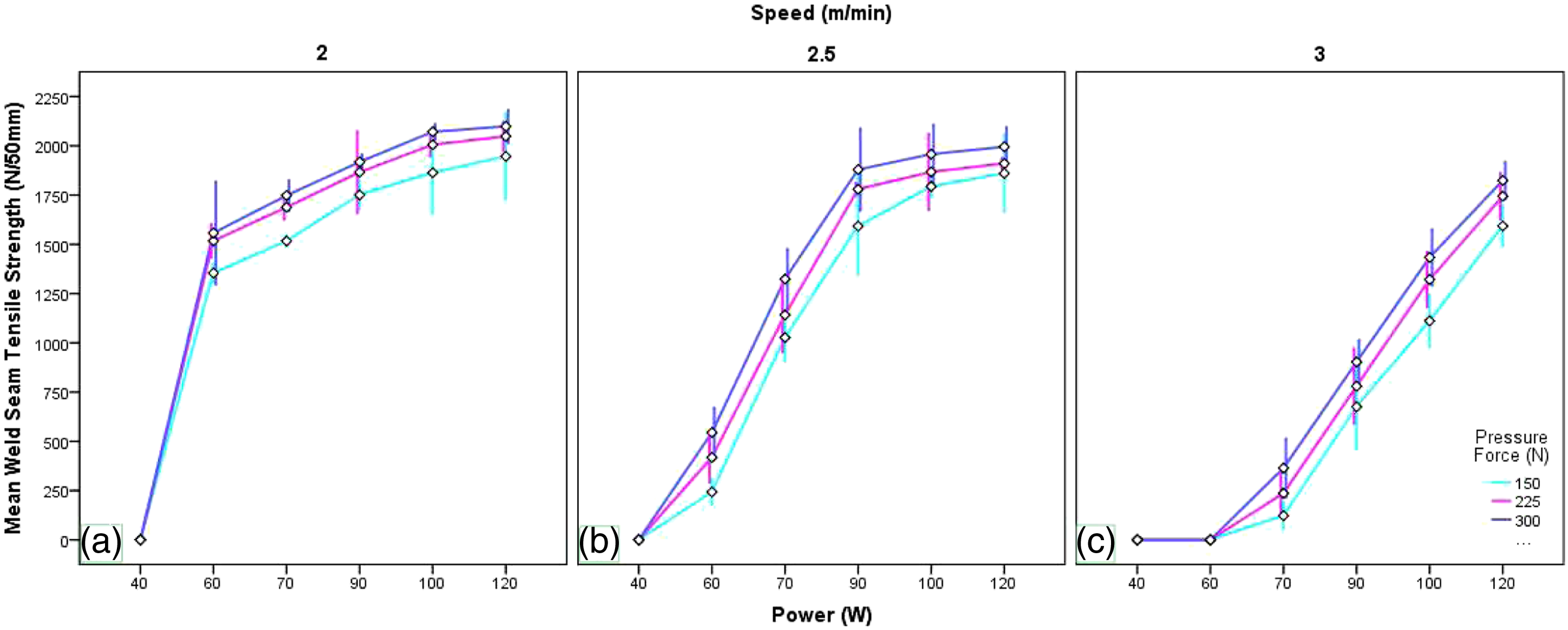
A relatively lower changing effect of welding power on weld seam tensile strength was observed at welding pressure forces of 150, 225, and 300 N for a welding speed of 2 m/min when the welding power increased. Due to a lower welding speed, a higher number of cycles of mechanical vibration reached up to the material and generated higher heat in all welding levels of pressure force between the horn and material. Thus, the changing effect was small due to a closer amount of heat generation on the material interface for all welding levels of pressure force. On the other hand, a pronounced changing effect of welding power was detected at the highest welding speed of 3 m/min because of decreasing generated heat in the contact area when the anvil roller’s speed increased. The changing effect was high due to a higher difference achieved between the lowest and highest welding power levels on the lower value of weld seam tensile strength. According to the analyzed results, it can be concluded that the changing effect of welding power was decreased with rising welding pressure force (from 150 to 300 N) in the case of all welding speeds but increased with rising welding speed (from 2 to 3 m/min) for all welding pressure forces. In other words, a higher changing effect of welding power was found at the lowest welding pressure force of 150 N than the highest welding pressure force of 300 N for all welding speeds, and a higher changing effect of welding power was attained at the highest welding speed of 3 m/min compared to the lowest welding speed of 2 m/min. However, the strongest weld seam was obtained at the highest welding power and lowest welding speed. Thus, a lower welding speed was required to attain the same level of bond strength due to a decrease in welding power. Figures 9(a)–(c) elucidates that the weld seam tensile strength as a function of welding power of 40, 60, 70, 90, 100, and 120 W at different anvil wheel welding speeds of 2, 2.5, and 3 m/min in the forward direction is plotted for different welding pressure forces of 150, 225, and 300 N.
Welding Speed
It can be inferred from Figures 10(a)–(c) that the weld seam tensile strength was decreased by 82.04, 72.43, and 65.02% at 60 W welding power, 61.42, 58.21, and 52.91% at 90 W welding power, and 18.17, 14.85, and 13.08% at 120 W welding power for welding pressure forces of 150, 225, and 300 N, respectively, when the welding speed rose from 2 to 3 m/min in the case of all welding pressure forces except for the welding power of 60 W at the highest welding speed of 3 m/min; the same was observed for a welding power of 40 at welding speeds of 2, 2.5, and 3 m/min. These results showed that the welding speed had a higher negative effect on the tensile strength of the weld seam. This is due to the higher difference between the number of cycles of mechanical vibration that reached up to the material interface at the lowest and highest welding speeds of an anvil wheel based on a specific welding pressure force and power. The weld seam tensile strength slightly decreased initially and then began to drastically decrease within the optimal working range of welding speed to some extent. A similar observation was reported by research
6
that the weld strength was initially increased as welding time increased, but a further increase in weld time caused a decrease in the strength. Welding time and the number of cycles of mechanical vibration were decreased once the roller welding speed increased. Lower heat was generated by lower vibration at the joint interface that resulted in a reduction of weld seam tensile strength. This observation was supported by research
3
according to which welding strength decreased as the welding speed increased because the temperature at the sealing point increased once the sealing speed decreased, which led to an increase in the amount of energy transferred to soften and melt the material; thus, the rise in fabric temperature at a longer sealing time allowed to form a stronger bond compared to the shorter welding time. Frankel and Wang 6,40 investigated that the highest joint strength was obtained in the case of the longest weld time and lowest weld force because of increasing energy dissipation and strength with increasing welding time. Weld seam tensile strength (N/50 mm) as a function of speed (m/min) for 12 mm welding width.
Welding speed affected the bond strength most noticeably when bonding at the lower welding power of 60 W, where the difference between the highest and the lowest value of weld seam tensile strength was highest to all welding pressure forces. The value of weld seam tensile strength at the lowest welding power of 40 W, cf. Figures 8 and 10, was proof of a reduction of weld seam tensile strength to a large extent with the rising welding speed; although increasing the sonotrode speed increased the friction work and transferred ultrasonic energy to the interface. On the other hand, a lower changing effect of welding speed was achieved at the highest welding power of 120 W for welding pressure forces of 150, 225, and 300 N as a welding speed increased. This is due to a closer amount of transferred ultrasonic energy to the interface at the highest and lowest welding speed. Thus, the amount of energy transferred to the welding area was strongly affected by the welding power compared to welding speed because the ratio of energy stored to the energy dissipated was influenced by the rate of ultrasonic oscillation. With other applied welding powers, the impact of welding speed on bond strength was not too pronounced. Based on the analyzed results, it can be concluded that the changing effect of welding speed on bond strength was decreased either the welding power changed from 60 to 120 W for all welding pressure forces, or the welding pressure force changed from 150 to 300 N for all welding powers. In other words, a higher change was attained at the lower welding power of 60 W compared to the highest welding power of 120 W for all welding pressure forces. Figures 10(a)–(c) display that the weld seam tensile strength as a function of anvil wheel welding speed of 2, 2.5, and 3 m/min in the forward direction at different welding pressure forces of 150, 225, and 300 N is plotted for different welding powers of 40, 60, 70, 90, 100, and 120 W.
Effects of ultrasonic weld parameters on width of weld seam
This experiment was carried out using 6 and 12 mm anvil widths to investigate the effect of anvil wheel welding width on weld seam tensile strength based on 33 factorial designs. Considering this, the same level of welding pressure force (150, 225, and 300 N), power (40, 70, and 100 W), and speed (2, 2.5, and 3 m/min) were utilized for both welding widths of anvil wheel. There are three different available welding widths of anvil wheel (3, 6, or 12 mm) with two different diameters (40 or 65 mm) on the machine setup, but 6 and 12 mm anvil wheel welding widths with 65 mm diameter were considered for our research purpose based on the preliminary experimental results. Tensile strength of the weld seam was determined for 21 and 18 out of 27 welding combinations using 6 and 12 mm welding widths of anvil wheel, respectively, to compare and investigate the effect of welding width on bond strength at the same welding levels. Figures 11(a)–(c) shows that the weld seam tensile strength as a function of welding pressure force of 150, 225, and 300 N and power of 40, 70, and 100 W at different constant welding speeds of 2, 2.5, and 3 m/min in the forward direction is plotted for different anvil wheel welding widths of 6 and 12 mm. Weld seam tensile strength (N/50 mm) of 6 and 12 mm welding widths at 2 (a), 2.5 (b), and 3 (c) m/min welding speeds.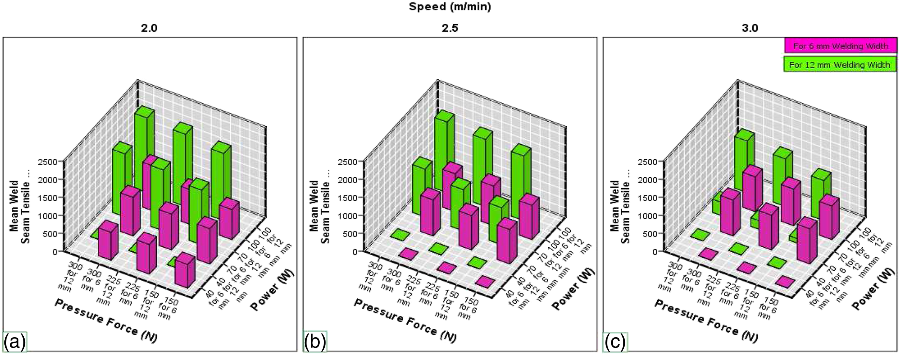
It can be inferred from the plot that the weld seam tensile strength varied from 657.34 to 1246.23 N/50 mm at 2 m/min welding speed, 951.36 to 1100.77 N/50 mm at 2.5 m/min welding speed, and 930.71 to 1014.41 N/50 mm at 3 m/min welding speed using 6 mm welding width of plain anvil wheel. The minimum tensile strength of the bond (657.34 N/50 mm) was obtained for the lowest welding pressure force (150 N) and the lowest welding power (40 W) at the lowest welding speed of 2 m/min, whereas the maximum (1246.23 N/50 mm) was found in the case of the highest welding pressure force (300 N) and power (100 W) at the lowest welding speed of 2 m/min, cf. Figure 11(a). On the other hand, it can be inferred from the plot that the weld seam tensile strength ranged from 1516.45 to 2071.28 N/50 mm at 2 m/min welding speed, 1026.75 to 1957.15 N/50 mm at 2.5 m/min welding speed, and 122.59 to 1433.72 N/50 mm at 3 m/min welding speed using 12 mm welding width of plain anvil wheel. The maximum tensile strength of weld seam (2071.28 N/50 mm) was observed for the experimental combination that was utilized to reveal the effect of welding width for the highest welding pressure force (300 N) and welding power (100 W) at the lowest welding speed of 2 m/min, cf. Figure 11(a), whereas the minimum (122.59 N/50 mm) was obtained in the case of the lowest welding pressure force (150 N) and medium welding power (70 W) at the highest welding speed of 3 m/min, cf. Figure 11(c).
It was investigated from the Figures 11(a)–(c) that the maximum value of weld seam tensile strength of 12 mm welding width showed an increment of up to 166.20, 177.80, and 141.34% for welding speeds of 2, 2.5, and 3 m/min compared to a 6 mm welding width of anvil wheel, respectively. Except for the highest welding speed of 3 m/min, the minimum value of weld seam tensile strength of 12 mm welding width showed an increment of up to 230.70 and 107.93% for welding speeds of 2 and 2.5 m/min compared to the anvil wheel welding width of 6 mm, respectively. Therefore, the weld seam tensile strength of the 12 mm welding width of the anvil wheel was higher than 6 mm. The impact of the welding pressure force was decreased when the welding width of the anvil wheel increased because the amount of stress developed in the welding area was inversely proportional to the welding width of the anvil wheel. Due to a higher effect of welding pressure force, a developed frictional work was decreased in lower welding width of anvil wheel (6 mm) than the higher (12 mm), and dissipated friction (due to surface effect) caused a higher plastic dissipation for lower welding width of anvil wheel (6 mm) than the higher (12 mm). Thus, a higher plastic dissipation caused a higher material deformation that resulted in a lower weld seam tensile strength for the lower welding width of the anvil wheel (6 mm) than the higher (12 mm).
The major welding parameters that affected the seam quality of ultrasonic welding of hybrid textile material in the lapped joint configuration were summarized and presented in Table 6 using Figure 4 as a mean and variation of the width of the heat-affected zone in the weld seam. It was reported that several welding parameters such as welding power, welding pressure force, welding speed, thickness, and focused position had a major effect on weld pool geometry (particularly on the width of the heat-affected zone in weld seam or welding surface area) that resulted in mechanical properties (particularly on tensile strength) during ultrasonic lap welding.1,41 A mean and variation results of the width of the heat-affected zone in the weld seam showed that the welding power was proportional to the width of the heat-affected zone in the weld seam. In other words, the width of the heat-affected zone in the weld seam increased as the welding power increased. Since the power and energy generated between welding areas were positively correlated, the energy input and dissipation increased by higher welding power and heat that resulted in higher width of the heat-affected zone and tensile strength of the weld seam. As the welding pressure force increased, the width of the heat-affected zone in the weld seam was increased up to a certain limit because of its little positive effect. Welding speed, on the other hand, was inversely proportional to the anvil width of the weld seam and width of the heat-affected zone. This observation was supported by research1,13,41 according to which welding speed was the most important factor for residual stress, which rose in a heat-affected zone while a focus position was not too relevant with residual stress. Either of the positive or negative effects of ultrasonic welding process parameters on the width of the heat-affected zone had their own direct impact on weld seam tensile strength. It can be inferred from Table 6 and Figure 4 that a uniform welding width, as well as a higher tensile strength throughout the length of the weld seam, was observed for an anvil wheel welding width of 12 mm than 6 mm. The welding width of the anvil wheel played an important role for deciding weld seam quality as well as their strength. It can be concluded that the tensile strength of ultrasonic welding of lap joints mainly depended on the welding width of the anvil wheel, width of the heat-affected zone, depth of penetration, and length of the weld seam. It was reported and well-known that the thickness for ultrasonic lap welding must be controlled within a certain threshold otherwise the two parts would not be joined correctly. 29 This threshold value of the thickness was correlated with the width of the weld seam. Thickness had a negative effect on the depth of penetration, 29 and the depth of penetration was inversely proportional to the welding width of the anvil wheel.
Thermal, chemical, and welding performance analysis of hybrid textile material
Welding performance analysis
The mechanism for generating bond strength in ultrasonic welding is that hot welt material macromolecules diffuse under the welding stress action produced by Van der Waals forces. 42 Interfacial bonding was developed due to ultrasonic welding through surface melting of the coating material by interfacial friction, and/or bonding was also developed due to heating by intermolecular friction. As Sascha35,43 reported, the real bonding process was induced by intermolecular diffusion processes, which required heat to enable molecular motion and entanglements. Potente35,43 stated that either intermolecular or a combined intermolecular and interfacial friction arose during ultrasonic bond formation. Melting first occurred at the interface due to pronounced asperities at the interface and severe vibration energy. 6 The formation mechanism of the weld seam is shown in Figure 1(c). Through the action of the ultrasonic wave, the phase transition from solid to liquid takes place at the welded parts and then the joint region is welded after the liquid is solidified. 6 Roller welding pressure force enhanced the spread of material macromolecules and eliminated weld residual gas in the gap. Roller welding speed controlled the cooperating time of power and roller pressure force. Good welding strength required matching of welding power, pressure force, and speed because each ultrasonic welding parameter had its own effect on weld seam strength as per its magnitude and direction.
Thermal analysis
Differential Scanning Calorimetry thermogram of untreated and ultrasonically treated hybrid textile is shown in Figure 12. Onset to end temperature of the glass transition zone was observed in Figure 12 between 50.07 and 116.73°C with a midpoint at 83.4°C for untreated sample, which is normally found for a fully PVC-coated woven polyester fabric. When the sample was subjected to ultrasonic energy, the glass transition zone (onset to end temperature) was changed and illustrated in Figure 12 between 63.4 and 123.4°C with a midpoint at 93.4°C. Compared to the untreated result, the treated sample exhibited two main changes in the glass transition zone, which were identified as size and location (shift) changes. Size change represents a change in the amount of amorphous that detecting the glass transition temperature. The observed size change was small for the treated sample; thus, the amount of amorphous that detecting a particular glass transition temperature was reduced due to the ultrasonic treatment. Since glass transition temperature measures the ability of molecules to move, it is important to study the location change that represents a change in the mobility of molecules. The glass transition of the treated sample was shifted to a higher temperature as shown in Figure 12. This is due to the change in the polymer or the environment that makes the molecule more difficult to move and led to shift the glass transition at a higher temperature. This may not be attributed to the breakages of some of the weak bonds in the noncrystalline mesophase zones and allowing the chains to start moving in the amorphous regions at a higher temperature. The presence of plasticizer in flexible PVC coating material makes the molecule easier to move at glass transition temperature and caused the glass transition to shift to a lower temperature. Because plasticizers increase the flow and thermoplasticity of a polymer by decreasing the viscosity of the polymer melt, the glass transition temperature, the melting temperature, and the elastic modulus of the finished product without altering the fundamental chemical character of the plasticized material. Differential scanning calorimetry thermogram of untreated and treated hybrid textile material with ultrasonic energy.
Three separate peaks were observed in the untreated sample. The crystal-melt onset temperature was at 134.71°C and reached a peak at 137.38°C for PVC, while the PET exhibited a crystal-melt onset temperature at 300.90°C that peaked at 320.14°C as shown in Figure 12. The first and the last peaks were because of the two different materials (PVC and PET) with two different crystalline structures that were used to make the hybrid textile material as a component. Observed separate melting behavior, cf. Figure 12, was not due to the presence of two different crystalline structures in one material. Plasticizers are most often used in PVC. Plasticizers are organic substances that intercalate the rigid polymer structures of the material for easy movement and flexibility. The presence of plasticizers in the PVC structure influences different specific physical–mechanical properties. Thus, the middle peak was produced due to the presence of plasticizer in PVC and had shown the crystal-melt onset temperature at 251.65°C and reached a peak at 256.66°C. However, a treated sample had shown two mainly observed separate peaks. A crystal-melt onset temperature was revealed at 136.06°C and reached a peak at 144.11°C for PVC, while the PET exhibited a crystal-melt onset temperature at 307.05°C that peaked at 322.83°C as shown in Figure 12. This is because of the presence of two different crystalline structures in two different materials having separate melting behavior. Since a plasticizer is volatile, ultrasonic treatment can reduce the amount of plasticizer that is presented in the material. Thus, the middle peak shown in the untreated sample has not produced a significant peak in the treated sample due to the volatility of the plasticizer during ultrasonic welding. Therefore, it can be concluded that the glass transition and melting temperature were shifted to a higher temperature when the amount of plasticizer was reduced by ultrasonic welding and observed evidence of that in Figure 12. Also, the middle peak of the untreated sample and the first peak of the treated sample had shown a signal variation having multiple peaks that essentially an overlay of two melting peaks. This mostly is because of having two different crystalline morphological structures in one material. When the material crystalline structure has a roughly symmetric arrangement with defects, it will going to melt more easily and will show up at a lower temperature melting peak due to a high-energy crystalline structure. If it is a highly ordered structure, on the contrary, it will going to melt at a higher temperature and will show the peak at a higher temperature. Furthermore, there is a difference in the shape of the melting peak where the treated sample shows a broad and sharper crystal-melt peak. The result showed 59.03 and 62.74% degrees of crystallinity for untreated and treated samples, respectively. This phenomenon is attributed to higher crystallinity ( > 3%) and more molecular order of the polymer microstructure. When the ultrasonic energy was applied to the hybrid textile that raises the temperature near melting causing the intermolecular bonds to have the most energy to melt and consequently short-length molecules move to form more stable intermolecular bonds resulting in better perfection and crystal growth. A similar observation was reported by Subhas and Renuka. 3 Besides, the rate of temperature change and the maximum temperature developed in the weld area depend on the thermal properties of fabrics and welding parameters as Shi and Little 6 reported. Under the same weld condition, the peak temperature and rising rate of temperature for different kinds of fabrics are different because of their different thermal conductances. Higher thermal conductances usually resulted in higher rates of temperature change.3,6 Thus, thermal conductivity affects the absorption of the ultrasonic wave in solids and hence the rates of temperature change during the welding process.
Chemical analysis
Figure 13 displays that the FT-IR spectra as a function of wavenumber from 4000 to 400 cm−1 at a resolution of 4 cm−1 are plotted for hybrid textile material before and after ultrasonic welding. It can be inferred from the plot that no new considerable chemical group or bond formation was formed under ultrasonic bonding conditions. It can be concluded that the ultrasonic bonding mechanism is a physical process rather than a chemical process according to the spectra analysis, cf. Figure 13. The ultrasonic bond is, therefore, resulted from molecular diffusion and inter-fiber encapsulation at high temperatures. When ultrasonic vibrations were turned off, such a state was stiffened and a joint was attained, which was described by Shi and Little.
6
This observation was supported by research
6
according to which a new chemical bond formation within the normal range of operation was not found, although at extreme conditions polymer degradation may occur while studying the seam formation using ultrasonic energy with 50/50 nylon/cotton fabric and polyurethane films. Chemical reactions during the ultrasonic welding of thermoplastics had been detected,35,44 but in other studies 35,36 were estimated to be less important and not responsible for bonding and caused by degradation because of the heat.
35
The only noticeable change was due to a slight increase in molecular weight as Subhas
3
reported while studying the microstructure of ultrasonically welded polyethylene. FT-IR spectra for hybrid textile material before and after ultrasonic welding.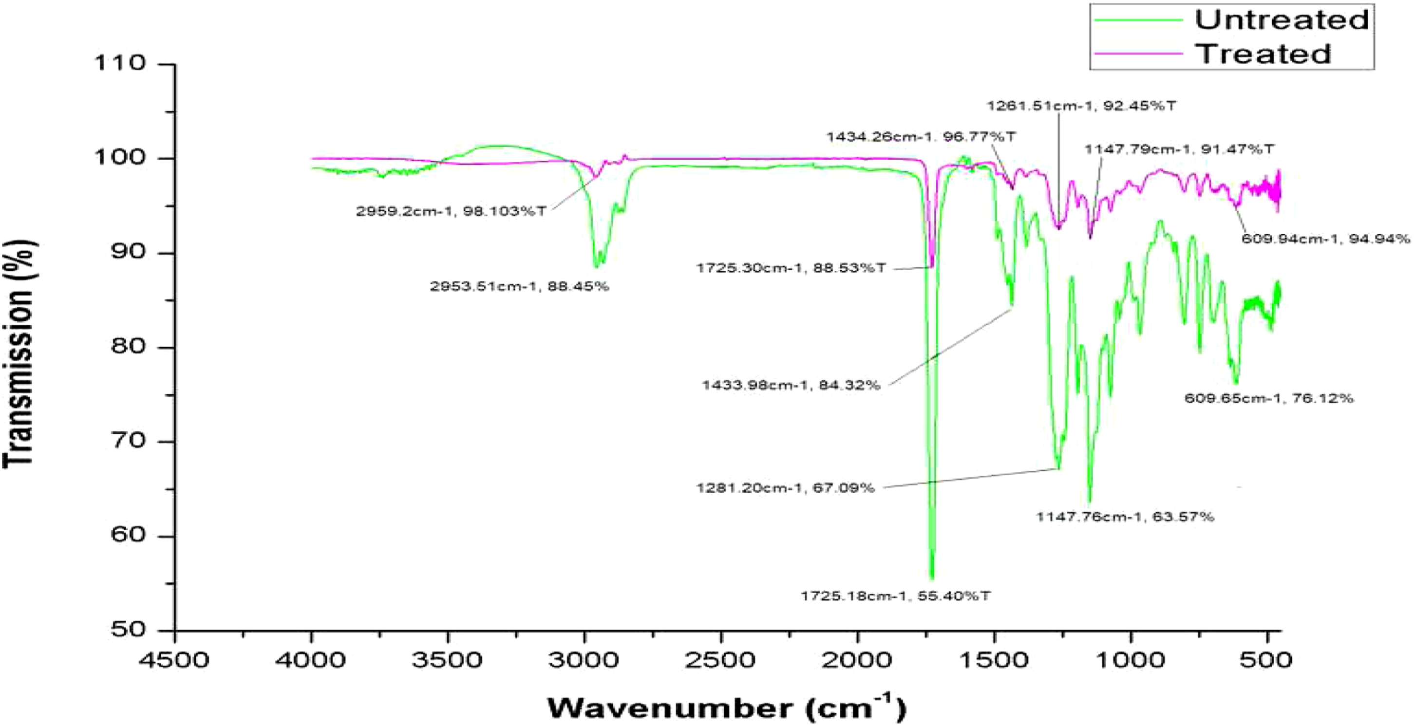
Numerical model and correlation analysis for seam strength of ultrasonic weld
Evaluation of statistical analysis
Both regression models for 6 and 12 mm welding widths of anvil wheel were significant and showed that the input variables were a significant predictor of weld seam tensile strength. Fitting aptness was assessed by comparing the coefficient of determination (R2) because the R2 was a statistical measure that represented the proportion of variance for the dependent variable explained by independent variables in a regression model. A higher R2 showed that the better the model was fitted to the experimental data. The R2 was very higher (more than 0.9) in Table 7, thus the fitted models can be used to predict the relationship between the input variables and weld seam tensile strength. Both models were fitted because the difference between Adjusted R2 and Predicted R2 was less than 0.2 and their difference was 0.1210 and 0.0583 for 6 and 12 mm welding widths, respectively. Adequate precision determined the ratio of signal to noise. Since a signal-to-noise ratio was greater than 4 in Table 7 for both welding widths, a fitted model can be used to navigate the design space. Multiple correlation coefficients (R) were very higher (94.8 and 96.3%) or more than 50% for both welding widths in Table 7, which explained the strength of the relationship between weld seam tensile strength and input variables. As presented in Table 8, the main independent variables, welding power (P), and speed (V) were significant predictors of weld seam tensile strength for 6 and 12 mm welding widths of anvil wheel except for the welding pressure force (F). The interaction effect between the welding power and speed (P*V) was a significant predictor of weld seam tensile strength for both welding widths of anvil wheel, whereas welding power square (P2) was a significant predictor of weld seam tensile strength for a 6 mm welding width of anvil wheel. It was investigated from Table 8 that the welding pressure force and power had a positive correlation with the weld seam tensile strength at the two-tailed significant value of 0.313 and 0.000 for a 6 mm welding width and 0.305 and 0.000 for a 12 mm welding width, respectively. However, the welding speed had a negative correlation with the two-tailed significant value of 0.000 and 0.001 for 6 and 12 mm welding widths, respectively. Since a two-tailed correlation was significant at the 0.01 level, the welding power and speed had a significant correlation value with weld seam tensile strength for both welding widths except welding pressure force.
Formulation of numerical model
Based on the suggestion given in fit summary analysis, a sequential model sum of squares analysis, and model summary analysis of the Design Expert 11, a nonlinear (quadratic) numerical model was formulated with a two-factor interaction (2FI) for weld seam tensile strength of 6 mm welding width, whereas a 2FI linear numerical model was also formulated for weld seam tensile strength of 12 mm welding width. By selecting the highest order polynomial where the additional terms were significant and the model was not aliased, and by focusing on the model which maximized the Adjusted R2 and the Predicted R2 values. Considering a significant value (p-value) of welding pressure force, power, and speed with their interaction effects mentioned in Table 8, two nonlinear and two linear numerical models were formulated for weld seam tensile strength of 6 and 12 mm welding widths, respectively, using estimated coefficient and actual equation of the factors. The estimated coefficient represented the expected change in response per unit change in the factor value when all remaining factors were held constant. These developments resulted that the intercept was the overall average response of all the runs and the coefficients were adjustments around that average based on the factor settings. Whereas, the equation in terms of actual factors can be used to make predictions about the response for given levels of each factor and the levels should be specified in the original units for each factor. To determine the relative impact of each factor, this equation could not be used because the coefficients were scaled to accommodate the units of each factor and the intercept was not at the center of the space of the design. Equations (5) and (7) are expressed the weld seam tensile strength based on the estimated coefficient for 6 and 12 mm welding widths, respectively, while equations (6) and (8) are expressed the weld seam tensile strength based on actual equation factors for 6 and 12 mm welding widths, respectively, as listed in Table 8. Based on the quations, the surface plot of weld seam tensile strength was constructed to show the design points above and below the predicted value in Figures 14 and 15 for 6 and 12 mm welding widths at welding speeds of 2, 2.5, and 3 m/min. The actual verse predicted value of weld seam tensile strength is shown in Figures 16(a) and (b) for 6 and 12 mm welding widths considering zero as no-weld, respectively. Surface plot of weld seam tensile strength (N/50 mm) for 6 mm welding width at 2 (a), 2.5 (b), and 3 (c) m/min welding speeds. Surface plot of weld seam tensile strength (N/50 mm) for 12 mm welding width at 2 (a), 2.5 (b), and 3 (c) m/min welding speeds. Actual vs predicted for weld seam tensile strength (N/50 mm) of 6 mm (a) and 12 mm (b) welding widths.


Correlation Analysis of Weld Seam Variation
Statistical correlation analyses were carried out to clarify the relation between weld seam and welding quality. First, as shown in Figures 17(a) and (b) and expressed in Equations (9) and (10), the following regression model described the relation between the average width of the top weld seam (w in mm) and weld seam tensile strength (T in N/50 mm) for 6 and 12 mm anvil widths, respectively. Correlation between average width of the top weld seam and tensile strength for 6 mm (a) and 12 mm (b) welding widths.


The coefficient of determination R2 shows that 99.8 and 96.7% of the variation of weld seam tensile strength was accounted for by the above regression model with the transformed average width of the top weld seam (log-transformation). The computed two-tailed Pearson Correlation value of 0.967 and 0.81 indicated that the investigated strong positive correlation between T and w was statistically acceptable at the 0.01 level of significance as per the investigated p-value of 0.000 and 0.000 for 6 and 12 mm anvil widths, respectively. In the same way, the observed relation between the variance of the top weld seam width (v in mm2) and weld seam tensile strength (T in N/50 mm) are described in Equations (11) and (12) by the following regression model for 6 and 12 mm anvil widths, respectively.

The coefficient of determination R2 shows that 92.9 and 96.0% of the variation of weld seam tensile strength was accounted for by the above regression model with the transformed variance of the top weld seam width (square-transformation). The computed two-tailed Pearson Correlation value of 0.460 and 0.563 indicated that the investigated strong positive correlation between T and v was statistically acceptable at the 0.001 and 0.05 level of significance as per the investigated p-value of 0.016 and 0.002 for 6 and 12 mm anvil widths, respectively. To visually verify the discovered trends in the weld seam, specimen at pressure force (350 N), power (120 W), and speed (2 m/min) of 12 mm welding width as shown in Figure 4 was selected; the upper picture had shown the variation of heat-affected width between the upper and lower extracted boundary curve in the top side with high tensile strength, while heated affected surface area shown in the last picture.
Numerical optimization of ultrasonic weld seam tensile strength
During a numerical optimization of weld seam tensile strength, the welding pressure force, power, speed, and weld seam tensile strength was set as a constraint. This numerical optimization was carried out using Design Expert 11 after setting the goal, lower and upper limit, and importance of all mentioned constraints. Maximize, minimize, target, in range, and equal to were the available options that were used to select for the goal of each constraint. The upper and lower limit was set based on the preliminary test results of the hybrid textile material using anvil wheel welding widths of 6 and 12 mm. The importance of each constraint can be set from one up to five values. Thus, the goal of welding pressure force, power, and speed was set within the range considering their importance as three out of five for each constraint. The lower to the upper limit of welding pressure force, power, and speed were set from 150 to 300N, 40 to 100 W, and 2 to 3 m/min for a welding width of 6 mm, and 200 to 350 N, 60 to 120 W, and 2 to 3 m/min for a welding width of 12 mm, respectively. The goal of weld seam tensile strength (response factor) was set to maximize the result within the lower to the upper limit (657.34 to 1246.23 N/50 mm) for a 6 mm welding width, and (122.59 to 2114.78 N/50 mm) for a 12 mm welding width considering their importance as five out of five. As the result, the optimal value of weld seam tensile strength of 1256.392 and 2116.93 N/50 mm were obtained at welding speeds of 2.033 and 2.045 m/min, welding powers of 75.636 and 119.901 W, and welding pressure forces of 296.778 and 230.314 N for 6 and 12 mm welding widths, respectively. According to these results, it would be suggested that the optimal parameters in the ultrasonic welding process should be based on the numerical optimization results. In this numerical optimization, 100 numbers of iterated possible solutions were generated and ordered by their importance, desirability, and target set to the tensile strength of the weld seam. Only one optimal welding combination was selected out of the possible solutions. Since the welding power is related to the cost and speed relates with production, both optimal solutions found numerically indicated that a lower production rate with a medium power-saving efficiency. The contour graph for desirability and weld seam tensile strength are constructed at optimal welding speeds of 2.033 and 2.045 m/min for 6 and 12 mm welding widths as shown in Figures 18 and 19, respectively. Contour plot of desirability and weld seam tensile strength for 6 mm welding width at 2.03,271 m/min optimal welding speed. Contour plot of desirability and weld seam tensile strength for 12 mm welding width at 2.04,513 m/min optimal welding speed.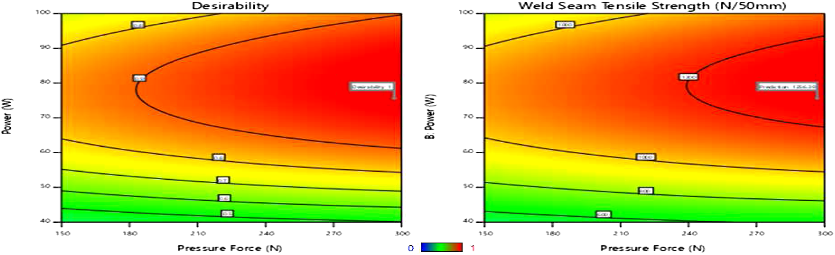

Effects of sewing parameters on conventional seam strength
A zigzag stitch has length and width. Stitch width is indicated the distance between the lines of the outermost parts of the stitches. It determines how far the stitch is gone from side to side.
33
Figures 20(a) and (b) showed that the conventional seam tensile strength as a function of stitch patterns of 2 and 3 at different stitch widths of 4 and 8 mm is plotted for different stitch lengths of 2 and 2.5 mm. The result revealed from the figure that all mentioned stitch combinations had the lowest seam strength in a stitch pattern of 2 compared to a stitch pattern of 3. The seam strength was increased when the stitch pattern changed from 2 to 3 at stitch lengths of 2 and 2.5 mm for stitch widths of 4 and 8 mm as shown in Figures 20(a) and (b) because a higher stitch per inch indicated a greater stitch density that consumed more thread in a stitch, resulted in a stronger seam. The value of seam strength was decreased with the rising stitch length and width. Therefore, the stitch length was indirectly proportional to the seam strength. As the stitch length increased, the number of loops that share the load decreased, resulted in a reduction of seam strength. These analyses agreed with the common idea that the longer stitch length created the needle to flex and increased the tension variation.44,33 Thus, the thread tension significantly influenced the seam strength. Both stitch length and width had a negative influence on seam strength while a stitch pattern had a positive relationship with the seam strength. These are not the only typical setting on the sewing machine to produce a significant effect on seam strength. Sewing thread linear density also affects the seam strength like stitch pattern, width, and length. This is attributed due to the fact that the finer thread has more tenacity than the coarser. Sealing tape has strength that contributes to the seam strength as well. Conventional sewn seam tensile strength (N/50 mm) as a function of stitch pattern for 4 (a) and 8 (b) mm stitch widths.
Conclusions
In this study, no new considerable chemical group (bond formation) was formed under ultrasonic welding. It was found that ultrasonically treated samples had a higher melting crystal-peak temperature and a highly ordered crystalline structure than that of the untreated samples. According to the numerical optimization, the optimal value of weld seam tensile strength of 1256.392 and 2116.93 N/50 mm were obtained at a welding speed of 2.033 and 2.045 m/min, power of 75.636 and 119.901 W, and pressure force of 296.778 and 230.314 N for 6 and 12 mm welding widths, respectively. The process efficiency evaluation of ultrasonic welding (166.67 TMU) was lower than that of the conventional joining technique (243.33 TMU). It was also found that the tensile strength value of the ultrasonic weld seam with a 12 mm welding width (2114.78 N/50 mm) was higher than that of the ultrasonic weld seam with a 6 mm welding width (1246.23 N/50 mm) and conventional seam (290.56 N/50 mm) against its maximum value. The effects of welding pressure force and speed on the tensile strength of the weld seam were smaller but important when compared with the welding power. Welding power was the most important welding process parameter affecting the weld seam tensile strength next to the welding width of the anvil wheel. Under the same ultrasonic welding conditions, the effect of 12 mm welding width on tensile strength was higher than that of 6 mm welding width. Based on the statistical analysis, it was concluded that the welding power and speed were significant predictors of weld seam tensile strength for 6 and 12 mm welding widths of anvil wheel except for welding pressure force. It was shown that pressure force and power had positive correlation values, whereas speed had a negative correlation value to the weld seam tensile strength for 6 and 12 mm welding widths. Moreover, the stitch length and width had negative influences on seam strength, whereas a stitch pattern had a positive relationship with the seam strength. The conventional seam rupture was at the seam line due to tape and sewing thread breakages, whereas the weld seam rupture was at the seam line due to ultrasonic bond breakage. In conclusion, ultrasonic welding can successfully replace the conventional sewing techniques in the industrial production of outdoor products for technical application when appropriate welding width of anvil wheel and optimal welding parameters are selected.
Footnotes
Acknowledgements
The authors would like to thank, Institute of Textile Machinery and High-Performance Material Technology (ITM), German Academic Exchange Service (DAAD), Ministry of Science and Higher Education (MOSHE), and Ethiopian Institute of Textile and Fashion Technology (EiTEX) for their valuable support to this research, and appreciate the Nucleus GmbH for allowing us to work on their machine, and also presents a special thanks to Tilo Pilling, Tina Anders, and Jessica Boll for their valuable assistance during production and testing.
Declaration of conflicting interests
The author(s) declared no potential conflicts of interest with respect to the research, authorship, and/or publication of this article.
Funding
The author(s) disclosed receipt of the following financial support for the research, authorship, and/or publication of this article: This research was funded by the German Academic Exchange Service (DAAD) through the EECBP Home Grown Ph.D. Scholarship Program 2019. The article processing charge (APC) was funded by the publication fund of the TU Dresden and Saxon State and University Library Dresden (SLUB).