
Abstract
Natural fibers and their waste are widely used all over the world, and their production has been increasing continuously. But, the rubber crumbs from used tire disposal are nonbiodegradable and present significant problems about their end-of-life given a critical environmental impact. These problems require recycling policies to provide the collection and recycling of used clothing, textile wastes, and rubber crumbs. In this work, the acoustic properties of insulator panels from the combination of textile fibers and rubber crumbs material were analyzed. Insulator panels demonstrated a good sound transmission loss (STL) characteristic, especially at high frequencies. The STL of the manufactured panels from a combination of fiber (cotton, wool, and Kapok) and rubber crumbs was investigated at the different sound frequencies. Results indicated that the fiber/rubber crumbs panel had a significant STL profile of 47 dB, 40 dB, and 35 dB, for Kapok, wool, and cotton, respectively. The addition of polylactic acid meltblown nonwoven fabric on the surface of the rubber crumbs side considerably increases the STL by 20%.
Introduction
The sound pressure is different for various machineries, based on the design of the machine and the running speed. The noise level in the textile machines varies between 85–120 dB, while it may reach 130–160 dB in the air jet engine. Any sound at or above 85 dB is more likely to damage hearing over time. According to the Occupational Safety and Health Administration (OSHA), the permissible exposure limit is 90 dBA for all workers for an 8-h day. A typical noise control application involves a combination of absorption of sound and transmission of sound energy by a variety of airborne and structure-borne paths. 13 The objective of this study is to design sound insulator panels to be fixed under the textile machine cover to reduce the noise emitted by the different moving parts, using textile fibrous material and rubber crumbs. The combination of natural fiber and rubber crumbs material exhibits an encouraging sound transmission loss (STL) performance at the low-frequency region when compared with either pure natural fiber or granular composites.
Materials and methods
Material specifications
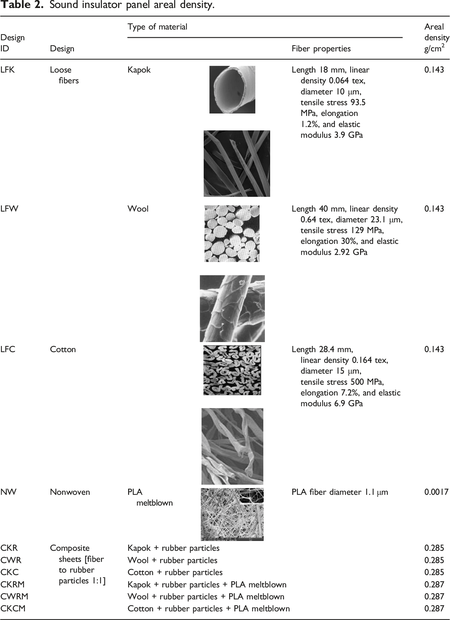
For preparing the composite panel, different types of fibers were used. The fiber properties under the investigation are as follows: Cotton fiber of the length 28.4 mm, fiber linear density 0.164 tex, fiber density 1.54 g/cm3, the average fiber diameter of 15 micro-meters, tensile stress 500 MPa, breakage elongation of cotton fibers 7.2%, and elastic modulus 6.9 GPa; Kapok fiber length of 18 mm and diameter 10 μm, fiber linear density 0.064 tex, fiber density 0.29 g/cm3, breaking strength and breakage elongation of Kapok fibers are 93.5 MPa and 1.2%, respectively, and elastic modulus 3.9 GPa.; and Wool fiber length of 40 mm, fiber diameter 23.1 μm, fiber linear density 0.64 tex, fiber density 1.314 g/cm3, stress and breakage elongation of wool fibers are 129 MPa and 30%, respectively, and elastic modulus 2.92 GPa. The polylactic meltblown nonwoven fabric has an areal density of 17 g/m2 with a thickness of 0.27 mm and an average fiber diameter of 1.1 μm. The composite consists of a fibrous sheet and the rubber particles obtained by the tiers grinding process by high-speed rotary mills
26
from the local supplier “EGITCO”. The rubber crumbs have different sizes; the actual size of the grain varies inside ranges from 5 μ up to 5 mm since the separation of the grains of different sizes takes place using a sieving process that splits the product into the crumbs as shown in Figure 1. In this work, mixed-rubber granules were used to increase the tortuosity to shift the maximum value of the coefficient of absorption toward lower frequencies.
11
Rubber crumbs.
Sound insulator panel areal density.
Processing of textile/rubber crumbs composite insulation panel
The cotton, wool, or Kapok fibers were used to form the sheet of fibers through the cold press under pressure. Composite panels were produced by varying fiber compositions which is probably desirable to reduce the chances of degradation of the fibers. The panel is formed from a compressed layer of fibers over which the rubber crumbs, of the different sizes and equal to the weight of the fibers, were randomly and uniformly distributed. Polyvinyl acetate (PVA) in a 2% percentage of the total sample weight was used to bond the rubber crumbs into the compressed textile structure through spraying. The sheet of fibers was formed by the required weight per square meter in a mold frame of 250 × 250 millimeter and pressed again through the cold press under a pressure of 50 kPa to reach the thickness of 5 mm. The panel was dried in an oven for 1 hour at the temperature of 105°C. Figure 2 shows the final shape of the manufactured panel. Sound insulator panel. (a) Panel (Kapok + rubber crumbs particles). (b) Kapok + rubber crumbs particles sheet cross-section. (c) Kapok + rubber crumbs particles + meltblown sheet cross-section.
The microscopic investigation of the fibers shows no change in the size of cotton, wool, or Kapok fiber after the formation of the manufactured panel.
Testing procedure
Mechanical testing of panels
Tensile properties of sound insulator panel.

Panels sound insolation testing
The developed sound insulation measuring setup is based on the acoustical chamber method,
27
as illustrated schematically in Figure 3. Circular samples of 10 cm in diameter were used for the acoustical measurement. The sound signals are fed to the laptop by a digital voice recorder from the actually measured sound from the running machinery at a particular speed. A digital sound pressure level meter is used, and its output is fed to the laptop. A signal generator or record by a digital voice recorder of the measured sound from the running machinery in the textile mills is sent to the loudspeaker. The test specimen holder is placed at an equal distance from the speaker and the digital sound pressure level meter. The sound waves were transferred through the sample of the sound insulator panel material to be measured by a digital sound pressure level meter and fed to the laptop to be analyzed using Audacity software. The measurements are repeated three times with and without sample and results are averaged. STL can be calculated, ASTM E2611, using the following equation13,14 Schematic drawing of the measurement setup.
27


The uncertainty of the measurement values on setup
Consider a variable Xi, which has a known uncertainty (t95% σ)
This statement should be interpreted to mean the following: The uncertainty in Y may be as large as ± t95% σ (is the best estimate of the correction due to systematic error, then measurand Y can be predicted). Where σ is the standard deviation of the population of possible measurements from which the single sample Xi was taken. Measurement uncertainty for every instrument and the analytical process has uncertainty. This will vary depending on the technique. The reported uncertainty is based on a t-distribution corresponding to a coverage probability of 95%. The value of (t95%) is equal to 2 to be confident at 95% for large values of degree of freedom. The STL values for several sound insulator samples were measured at different frequencies, ranging from 200 to 1600 Hz. The value of standard deviation ranged from 0.02 to 1.03.
To be sure that the measured results on setup are correlated with that in the real conditions in the mill, the sound pressure was measured on the actual machine in a real working condition using insulator panel and compared to the sound pressure measured on the setup using the same insulator panel. The results of the sound pressure in both cases were highly correlated as shown in Figure 4. Sound pressure measured on the ring spinning machine with sound insulator material versus sound pressure measured on setup with the same insulator material.
The Fast Fourier Transform transforms a function of the time domain into a function of the frequency domain. Fast Fourier Transform spectrum analyzer was used to analyze the signal and measure the sound in decibels at the different frequencies; the data from the test without the sample served as the baseline. 27 The data from the digital sound pressure level meter of the acoustical chamber are appropriate for obtaining the acoustical insulation information of the sound insulator panel material installed in the sample holder.
Results and Discussion
Analysis of sound insulator panel design
The main objective of the sound insulator panel is to reduce the sound pressure that passes through it. There are several methods for the design of the sound insulator panels which are the following: porous sound insulator panel and membrane sound insulator panel. 28 Sound waves, which can be seen as pressure fluctuations, generate alternating air flows inside the pores and the channels of the porous materials, which in turn are covered by the viscous boundary layer. In the case of the porous sound insulator panel using textile fibers, the STL depends on the frictional losses of the air when it moves within the material. High absorption depends on the distribution of the pores, their size, tortuosity, and the thickness of the material. The topography of the sound insulator panel’s surface plays a role in determining the sound reflection. 13 The pores might be of different sizes in the form of holes with the fibers crossing them at different levels on their lengths; these fibers will be forced to vibrate due to the sound wave. Thus, the pore diameter will depend on the fiber diameter and the distribution of the fibers in each layer as well as fiber orientation. The physics of sound transmission through porous materials is not typically the same and depends on the fiber cross-section physical structure and material porosity. 13 Porous sound insulator panels are the most common type of sound insulator panels. Textile fibers, fabrics, mineral wools, synthetic foams, and felts are all examples of porous sound insulator panels, just as home furnishings such as carpets, cushions, and curtains. Consequently, the choice of the suitable constituent material of the sound insulator panel should depend on the nature of the sound emitted from the source.
Design of sound insulator panel
The main contribution of the work was to design a panel for the sound insulation efficient to reduce sound noise emitted by the movement of the different machine mechanisms, which made the working environment not healthy, and which is one of the major requirements in many industries. Also, it is important to participate in the economical ways of producing sound-absorbing materials which are cheaper and eco-friendly.14,29
The sound isolation can be obtained in different ways, for instance, using a dense heavy material sheet or some textile fibers that possess sufficient sound isolation performance. Also, the sound insulator panel material can be separated by the air gaps. 14 Furthermore, the desirable sound insulator panel can be achieved by combining a granular, porous sound insulator panel, fibrous, micro-structure, and cellular. A polymer matrix can be added to develop a composite. The mentioned methods might be used separately or in various combinations to achieve a required sound insulator panel performance.
Figure 5 shows the main factors affecting STL of the textile fiber sound insulator panels. The sound insulator panel design should be suitable for damping the sound from the place it will be fixed in. Consequently, the first step is to analyze the sound spectrum at the source to choose the suitable material and design. Figure 6 shows the steps of the textile sound insulator panel design. Classification of different parameters of textile sound insulator. Steps for design and manufacturing of sound insulator panel.

Sound analysis of textile machinery
The sound waves recorded on the different textile machines were analyzed and found to be dependent on the machine’s mechanical design, speed, and type of mechanisms. Figure 7 shows the record of the sound for the ring spinning machine, weaving machine, and winding machine, which indicates that the presence of a mixture of sound waves with different frequencies and amplitudes. Sound-time history record and sound pressure dB for: (a) spinning m/c, (b) weaving m/c, and (c) winding m/c.
The sound pressure is a function of the operations and is featured by the different dynamic phenomena. In the case of a ring spinning machine, the increase of the spindle speed increases the sound pressure due to the dynamical behavior vibrations of the spindles as illustrated in Figure 8. Sound-time history record and sound pressure dB for spinning m/c at different spindle speeds.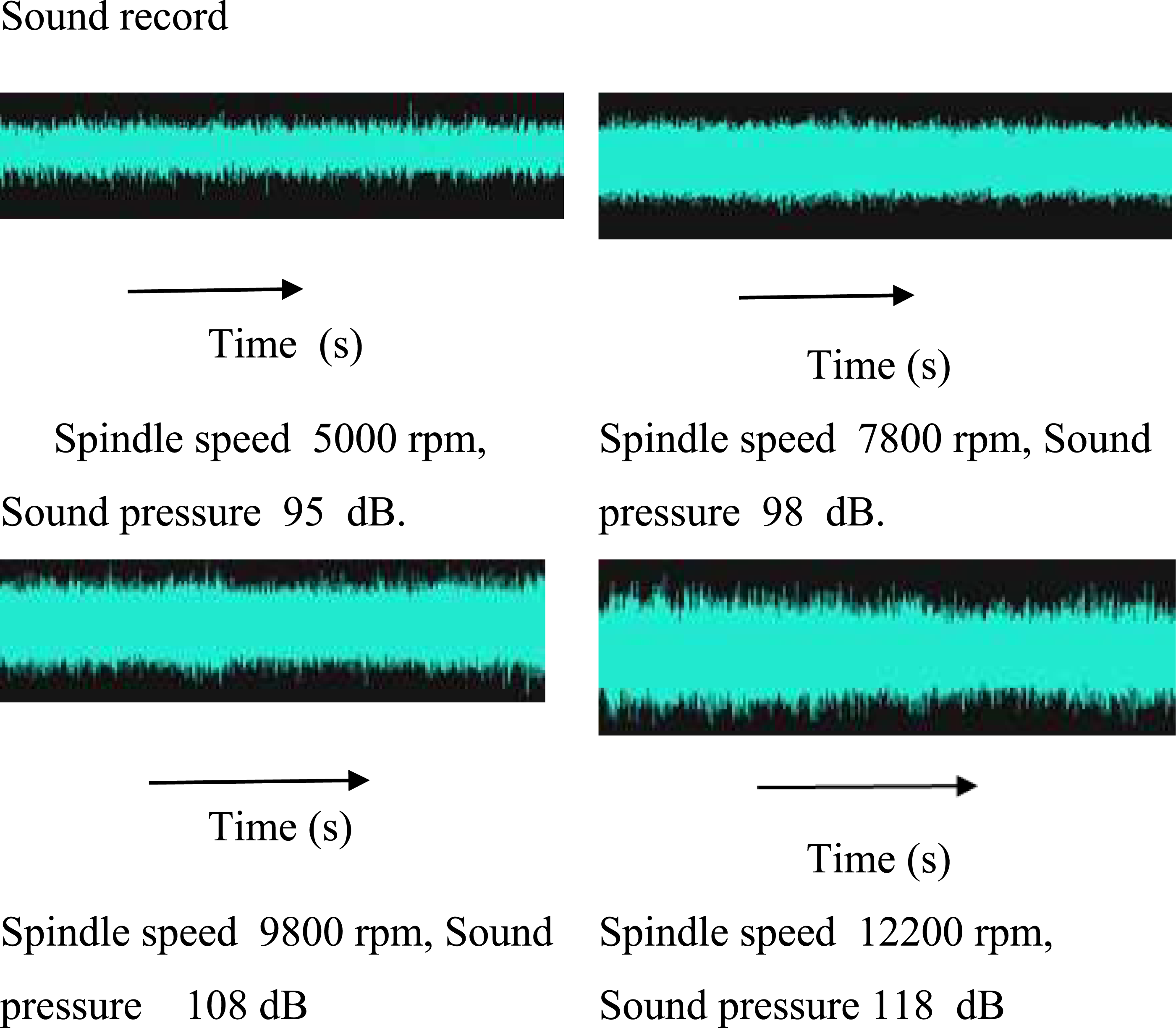
In addition to the static and quasi-static loads, different parts of machines can experience dynamic loads that cause vibrations. Vibrations of different parts induce pressure waves into the adjacent air which can be measured by a sound pressure meter placed close to the machine.
The sound pressure measurement analysis indicated that much of the research is focused on the modeling and measuring of the acoustic absorptivity of different materials and constructions rather than testing the effect of using sound insulator panel on the real sound of the different machines. Figure 8 shows the change of the sound record as a function of the spindle speed. The measured sound pressure dB increased as spindle speed varied from 5000 r/min to 12,200 r/min. This was mainly due to the increase in the vibration of the spindles.
STL of different panel designs
Sound records of ring-spinning machine.

Sound transmission loss for sound insulator panels.

The value of the standard deviation (σ) for the tested panels varied between 0.02 and 0.93. Generally, it has low values as the applied frequency gets higher. The calculation of uncertainty of the measured values was ±0.6 dB, at the probability of 95%. Moreover, with the use of PLA meltblown nonwoven, the standard deviation of the STL became less. The results are limited for range of sound frequencies 200–1600 Hz.
The STL in the composite samples formed from the fibers sheet and rubber crumbs particles on its surface is represented in Figure 9, while Figure 10 illustrates the STL when the meltblown layer was added. Comparisons of sound transmission loss for different panels design. Comparisons of sound transmission loss for different panels design with rubber crumbs meltbown nonwoven layer.

The panel, made from Kapok fibers and rubber crumbs particles, exhibited the highest STL, that is, the intensity of sound is reduced in the transmission through the panel, than those from cotton or wool fibers. The Kapok fiber has a huge lumen filled with air and a thin cell wall, 0.67–1.00 μm thick, 30 as well as a very low density of 0.29 g/cm3, while for cotton and wool it is 1.54 and 1.31, respectively. The length and fineness of the Kapok fiber are lower than cotton or wool. 31 This structure allows higher STL by a higher possibility for the sound wave to interact with the fibers. On the other hand, lower fiber density results in more reflection of the sound wave than transmission due to the higher number of Kapok fibers on the panel’s surface. Thus, the loss of more energy due to the viscous friction of the air molecules with higher surface area decreases the value of the sound transmission at the low-frequency region.32,33 Despite that the areal density of all three panels is the same, the volume fraction of the three composites varied (cotton panel CKR [0.83:0.57:0.047], wool panel CWR [0.447:0.524:0.04], and Kapok panel CKC [0.785:0.207:0.008]).
With the presence of the rubber crumbs particles on the surface of the samples, the sound wave is transmitted through the rubber crumbs, and as a result of viscous resistance between the surfaces of rubber and the air, the sound wave energy is partially converted into the form of thermodynamic energy during the initial transmission of sound waves through the irregular surface of the rubber crumbs. The transmitted sound wave loses more energy due to the vibration of the elastic system composed of rubber crumbs particles and the air space which are varied due to the different sizes of the rubber particles.26,34 It was found that the increase in surface roughness decreases transmitted sound pressure. 35
The addition of meltblown layer on the surface of the Kapok + rubber crumbs panel delivers STL values which vary from 54 to 60 dB at the frequencies from 200 to 1600 Hz, Figure 10, that is, the average value of STL increased by about 20%. This can be attributed to the energy loss as the sound wave passes through the meltblown nonwoven fabric, and the frictional resistance offered by entrapped air between the rubber crumbs particles surface and the fabric is overcome.20,26,36 The presence of micro-fiber meltblown nonwoven in the samples reduces the value of STL at all sound frequencies because its fibers have a higher surface area, Table 2, than the other fibers, resulting in a higher flow resistance, despite of its small thickness.33,37,38 The meltblown nonwoven structure has a low areal density, fiber diameter, and average pore diameter resulting in a relatively high coefficient of sound absorption, particularly in the middle-frequency region.13,14,27 In the case of the multi-layer structure, the STL mainly depends on the sound transmission of the layer directly facing the sound wave. When using a layer of the meltblown fabric over the rubber crumbs/fiber panel and due to the air gap between the two layers, the surface texture of the rubber crumbs is not smooth, therefore keeping air gaps increases the insolation of the panels. The differences between the three constructions of the panels, with or without the use of PLA meltblown nonwoven layer, are statistically significant. The STL of the panel (Kapok + rubber crumbs + PLA) reached 59.1 ± 0.8, which covers most of textile machinery sound frequency ranges up to 1000 Hz.
Frequency analysis of acoustic signal using Fast Fourier Transform
To analyze the success of using such panels design on spinning, weaving, and winding machines, first, we need to know the frequencies of the noise emitted from each one at a particular speed and then can take the measures to design the sound insulator to reduce it. Recording sound to a digital file and transforming the data by the Fast Fourier Transform is one of the ways how to accomplish that. Fast Fourier Transform analysis is a good choice for transforming some digital signals from the time domain to the frequency domain. Figure 11 illustrates the Fast Fourier Transform from the test, without the test sample, served as the baseline for the comparison to the Fast Fourier Transform when using differently prepared tested samples, fiber + rubber crumbs particles, on different machines. Fast Fourier Transform of transmitted sound results for different structures of panels (fiber + rubber crumbs particles) when applied to: (a) spinning m/c, (b) weaving m/c, and (c) winding m/c.
Figure 11 shows that for all machines at all frequencies up to 6000 Hz, the composite with the Kapok fibers exhibited the highest sound insulation effect, especially at high-frequency range, followed by the wool fibers and cotton fibers. In the case of the panel made from fiber + rubber crumbs particles + meltblown nonwoven tested on the different types of machines, Figure 12, the composite panel using Kapok fiber represents the excellent damping of the sound emitted from the ring spinning machine for all frequencies up to 6000 Hz. Meanwhile, both wool and Kapok fibers are acting similarly in insulating the sound in the case of weaving and winding machines. The PLA meltblown fiber average diameter was 1.1 μm and thickness was 0.27 mm. The thin fiber moves more easily in sound waves causing vibration in the air and enhancing the STL.22,32 The analysis revealed that the effect of the panel differs according to the sound characteristics emitted from the different machines under the investigation. Fast Fourier Transform of transmitted sound results for different sound insulator panel from (fiber + rubber crumbs particles + meltblown), when applied to: (a) spinning m/c, (b) weaving m/c, and (c) winding m/c.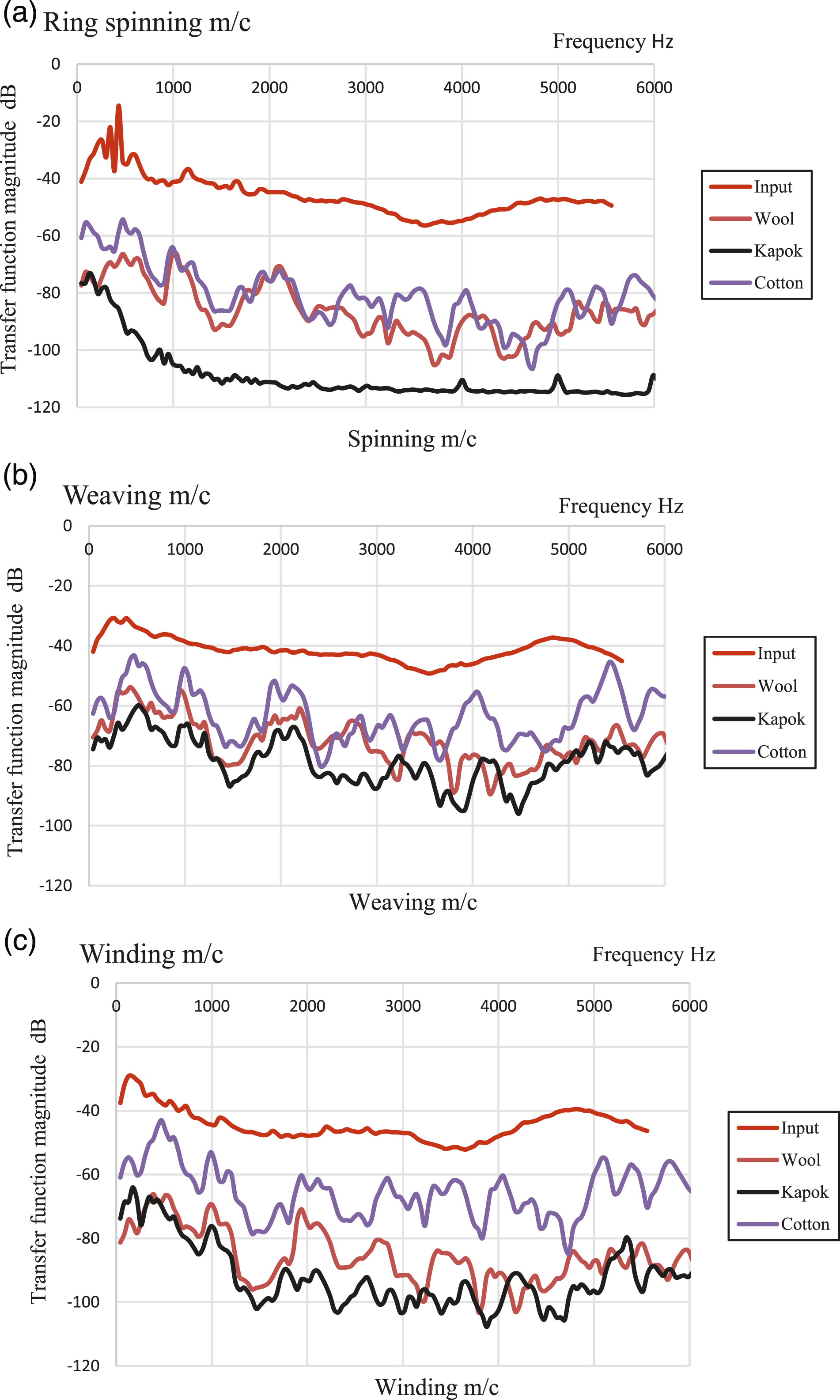
Conclusion
The sound insulator panels are widely used for the acoustic correction of the environments by damping the noise produced by various sources from the different parts of the machines. This work reports the results of an experimental investigation conducted on six specimens constructed from cotton, wool, or Kapok fibers, rubber crumbs and PLA meltblown nonwoven material. The simulator setup and the real measurements on the machine returned values of the R-squared coefficient equal to 0.99, demonstrating an excellent simulation. Results indicated that the fiber/rubber crumbs panel had a significant STL profile of 47 dB, 40 dB, and 35 dB, for Kapok, wool, and cotton panels, respectively. In average, STL was increased by about 20% when using Kapok fiber/rubber crumbs/PLA meltblown nonwoven composite panel compared to panels without PLA nonwoven layer at the sound frequency bands of 200–6000 Hz.
Footnotes
Declaration of conflicting interests
The author(s) declared no potential conflicts of interest with respect to the research, authorship, and/or publication of this article.
Funding
The author(s) received no financial support for the research, authorship, and/or publication of this article.