
Abstract
In this paper, graphene, graphene/matrix, and graphene/fiber nanocomposites, including their synthesis process, fabrication, properties, and potential applications, were reviewed. It was found that several synthesis techniques for nanographene were developed, such as liquid-phase exfoliation and chemical vapor deposition. In addition, some fabrication processes of graphene/matrix and graphene/fiber-based nanocomposites were made, including in-situ polymerization, nanostitching in that single layer nano graphene plate could be interconnected by means of carbon nanotube stitching, resin transfer molding, and vacuum-assisted resin transfer molding. Several properties, including mechanical, thermal, and electrical, on the graphene nanoplatelets materials were summarized in this review paper. It was realized that graphene, graphene/matrix, and graphene/fiber nanocomposites have extraordinary mechanical, thermal, and electrical properties used in advanced engineering applications, including soft robotics, microelectronics, energy storage, biomedical and biosensors as well as textile industry.
Keywords
Introduction
Numerous researches have been carried out to develop novel materials or tune existing materials with an inimitable combination of properties that can be replenished with the traditional metallic compounds, ceramics, and polymeric substances. Graphene nanoplatelets composite has certain potential used in high performance requiring areas such as space/aerospace, marine, defense, robotic, medical and transportation due to its high specific strength/stiffness ratio, chemical resistance, and better corrosion properties [1,2]. This requirement led to the advancement and expansion of nanocomposite materials. Due to their novel properties and diversified application usage, nanocomposites garnered increasing noticeable consideration as an indispensable part of our everyday life [3–5].
Graphene nanoplatelets (GNPs) composites have a high surface area to volume ratio, lightweight, easy to fabricate, and flexible [6–8]. The small amount of GNPs in neat composite improved its properties due to the enhancement of the interfacial region [9,10]. It has revealed that the inclusion of nanoparticles not only noticeably improved the interfacial bond but also increased the mechanical, thermal, and electric properties of composites [11–13]. To enhance the material performances, the interest of using nanomaterials as reinforcements such as carbon nanotubes (CNTs) [14–16] and graphene nanoplatelets (GNPs) [17–19] have been widely explored as fillers for their integration into polymer composites. As a result, their demanding properties were exploited to develop functional materials [20]. Graphene is a two-dimensional (2 D) atomic crystal material [21] and an array of one-atom-thick planar sheets comprised of sp2-bonded carbon atoms closely organized in a crystal honeycomb lattice. This makes them light and strong, including flexible and rigid material as illustrated in Figure 1. Charge carriers of graphene reveal excessive intrinsic mobility and can move for thousands of inter-atomic distances without scattering [22]. It shows higher thermal conductivity [23], impermeability, stiffness, and improved mechanical and optical properties [24–26]. Therefore, graphene and graphene-based nanocomposites show a range of prospective applications due to their remarkable properties, from high-performance electronic devices [27], to composite materials [28], and wearable electronics [29].

All graphitic forms of graphene as 2D flat nanosheet, top and 3D multilayered graphite formation, bottom [21].
This review was prepared in four sections. The first section dealt with various synthesis methods on graphene. The second section was on the fabrication method of graphene nanocomposites. The third section was related to the properties of graphene, and its nanocomposites, and the last one was related to the application of GNPs composites. Therefore, this review study provided comprehensive and diverse information on graphene nanoplatelets composites.
Synthesis of graphene
Graphene has a densely packed, huge surface area due to van der Waals interaction forces, and therefore, graphene layers tend to restack and reaggregate. Several attempts have been devoted to creating techniques for synthesis to achieve high-quality pristine graphene because of its planar hexagonal array and high aspect ratio. Mass-level production synthesis of graphene prevention of aggregation is a critical parameter. Finding a suitable and well-fitted fabrication method for mass-level graphene production and having defect-free graphene is the main objective. Generally, graphene synthesis approaches can be categorized into two categories as top-down and bottom-up methods. On the other hand, each method can be used depending on the end-use requirements. The methods are classified as presented in Figure 2, and the graphene synthesis methods are schematically shown in Figure 3. Mechanical exfoliation [31], chemical synthesis [32,33], chemical exfoliation [34,35] epitaxial growth [36–38], and chemical vapor deposition [39] have been extensively studied. Other methods including arc-discharge method [40], electrochemical exfoliation [41,42], microwave synthesis [43,44], gas-phase synthesis [45,46], total organic synthesis [47,48], solvothermal synthesis [49,50], unzipping of carbon nanotubes (CNT) [51,52] and flash graphene synthesis [53] have been well explained.

Classification of graphene synthesis techniques.

A schematic demonstration of various graphene synthesis methods. (a) Micromechanical cleavage, (b) anodic bonding, (c) photo exfoliation, (d) liquid-phase exfoliation, (e) growth on SiC, (f) precipitation from metal, (g) chemical vapor deposition, (h) molecular beam epitaxial and (i) chemical synthesis; Reprinted with permission from [30].
Mechanical exfoliation
Graphite consists of stacked layers of multiple graphene sheets, which are bound together by weak van der Waals forces. Graphene can be made from a pure graphite sheet by breaking these forces [54]. This method is a well-known simple technique for graphene production [31]. An adhesive tape is required, between which graphite flakes are placed and the outer side is peeled off constantly. This process is repeated. As the tape is peeled off and replaced with a new tape, the flakes break up into thinner flakes, and this repetitive process continuous until efficient single layers are accomplished. Through this process, exfoliation of graphite into few-layer and single-layer graphene sheets with lateral sizes can be possible. Geim et al. [21] makes a freestanding graphene sheet using thick, highly oriented pyrolytic graphite (HOPG) and a repetitive peeling-off process from the graphite. Then, the tape was dispersed in acetone solution, and an oxidized Si-wafer was dipped into the solution to move the flakes onto the substrate. The deposited flakes were extensively studied, especially for the electrical properties [55]. Mechanical exfoliation is a versatile and simple process to get defect-free graphene for fabrication, but the main obstacle is large-scale production. On the other hand, micromechanical exfoliation has been applied to fabricate graphene utilizing the mechanical process by generating shear forces. From the mechanical point of view, the main task is to mechanically overcome the Van der Waals’s attraction between the graphene layers within the bulk precursor. Chen et al. [56] made single and few-layer graphene sheets exfoliated from natural graphite via mechanical exfoliation using a three-roll mill machine with a polymer adhesive. Despite its shortcomings, micromechanical exfoliation persists as the preferred method for basic research.
Liquid-phase exfoliation
Liquid-phase exfoliation (LPE) has emerged as the most popular method for mass production. It is a simple and accessible process in which pristine graphite is exposed to a solvent to degrade the van der Waals forces between interconnected layers [57]. A schematic representation of the liquid-phase exfoliation process is shown in Figure 4. This process can be applied to exfoliate graphite in various liquid media by external driving forces such as ultrasonication, electric field, or shear forces to achieve spontaneous exfoliation into graphene sheets. Graphite is dissolved into an appropriate solvent followed by exfoliation. N-methyl pyrrolidine (NMP) and N, N-dimethylformamide (DMF) [59] are used as solvents. Liquid-phase exfoliation of graphite by ultrasonic techniques is of particular importance, as this simple process can produce neat graphene films ready for organic functionalization. This also allows the integration of additives, for example, surfactants [57], antioxidants [60], and polymers [61,62].

Liquid-phase exfoliation process of graphite, schematic; Reprinted with permission from [58].
The liquid-phase exfoliation process usually involves three operations: (1) graphite must be dispersed in a solvent, (2) exfoliation, and (3) purification [58]. The expansion and collapse of voids in liquids due to pressure fluctuations induce exfoliation through ultrasonication, cavitation, and shear forces. After that, the graphene-solvent interaction is required to stabilize the inter-sheet attractive forces [63]. Some of the solvents are not cost effective, corrosive, high boiling points, and are typically toxic. Ultrasonication-assisted LPE has been widely applied to prepare the dispersions of graphene; perhaps there is a problem of high energy-extensive consumption and lower efficiency. High-shear mixing and micro fluidization bring new strength to the development of liquid-phase exfoliation. Removing surfactants as dispersants is quite troublesome. As a result, prepared graphene may show poor performance in this method.
Chemical vapor deposition (CVD)
Chemical vapor deposition (CVD) is an efficient and well-known process to produce graphene. This process can achieve good quality, uniformity with many domains, controlled graphene layer numbers, and a large scale of the produced graphene with small defects [64]. CVD requires the activation of gaseous reactants and the resulting chemical reaction, with the generation of an invariant solid deposit over an appropriate substrate, for example, Ni [65], Cu [66], Fe [67], Pt [68], or their alloys [69], ethanol [70], methane [71], hexane [72] and botanic camphor [73]. CVD is a recognized and adaptable technique for graphene synthesis [74]. The CVD growth of graphene comprises two types of chemical reactions in its deposition process: homogeneous gas-phase reactions and heterogeneous chemical reactions [75]. The gaseous precursor undergoes pyrolysis to form carbon species, and it is placed on the outside of the substrate where nucleation develops, and the carbon structure of graphene grows. Typically, to lessen the reaction temperature and to enhance the pyrolysis of the precursor, a catalyst is utilized. Generally, the CVD graphene process involves eight steps, as illustrated in Figure 5 [74].
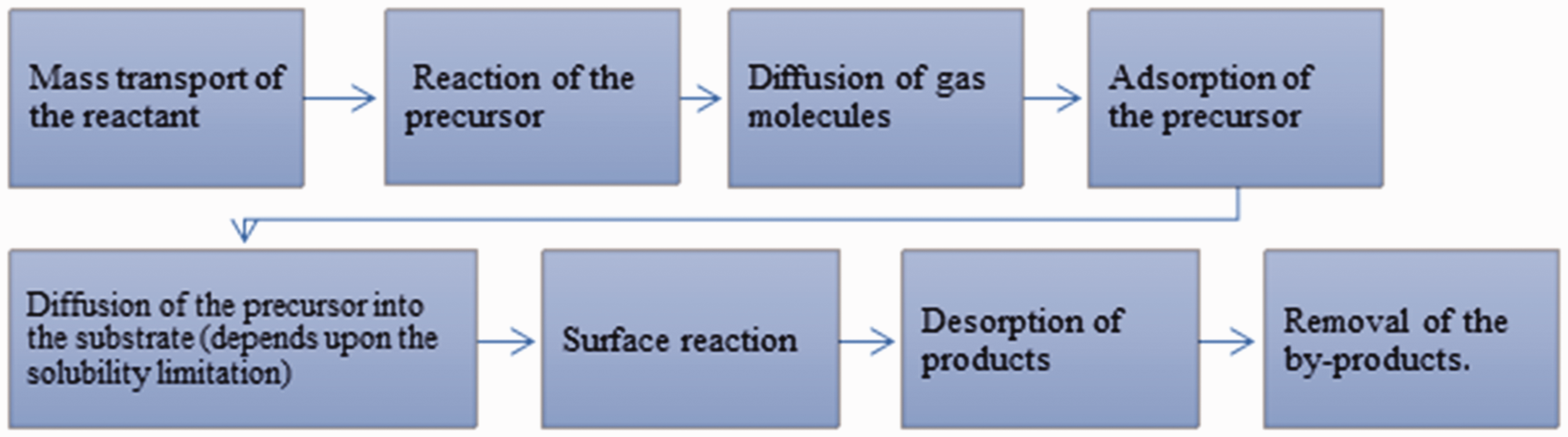
Steps involving chemical vapor depositions (CVD) graphene process.
A precursor in the CVD process requires that carbon-containing gasses (e.g., methane, CH4) or liquid vapors from carbon sources (e.g., alcohols) need to be decomposed on transition metals wherever carbon is soluble. Some carbon is thought to precipitate as a graphite film at improved temperatures (900 –1100°C) in metal when it is cooled. At high temperatures, pyrolyzed carbon atoms can form a graphitic structure from dissociated carbon atoms. Metal catalysts stimulate graphitic structure formation expansion as well as lower energy barriers for precursors pyrolysis. Among the various metal catalysts, such as Ni and Cu is desirable due to their etching ability and cost efficiency [66]. It has been reported that uniform graphene films were synthesized over a large area [65] via methane on Cu foils, were constructed for mass production of the graphene films [39]. Figure 6 shows thermal-CVD and plasma-enhanced CVD methods [75] schematically.

(a) Thermal-CVD and (b) Plasma- enhanced CVD processes where reactants transfer (1), thermal or plasma activation (2), from the main gas stream layer the boundary reactants transport through gas diffusion (3), adsorption of reactants (4), bulk diffusion of species (5), surface migration to the growth of the film (6), desorption of by-products (7), transport of by-products (diffusion) and return to the main gas stream (8), and by-products transportation from the deposition area (9) By-products transportation from the deposition area; Reprinted with permission from [75].
The chemical vapor deposition process (CVD) can be divided into two forms, thermal chemical vapor deposition [76,77] and plasma-enhanced chemical vapor deposition [78]. Thermal CVD is often used, and heating is the main driving criterion for the reaction. Ahmed et al. [79] reported single layer to few layers’ graphene on polycrystalline Ni by thermal CVD treating by solid precursor, camphor at ambient pressure. However, using plasma can facilitate pyrolysis temperature reduction. In the case of pressurized operation, there are two groupings, atmospheric-pressure CVD, and low-pressure CVD [80]. Substrate selection is crucially essential, and diversified substrates can be used. Metals, especially Cu, thrive the most as it acts as a catalyst and, the low carbon adsorption tendency of Cu allows easy control for the formation of large-area homogeneous mono or bilayer graphene. At low temperatures, the plasma produces reactive radicals of gaseous carbon precursors by pre-cracking, resulting in high-quality monolayer graphene films [81].
Epitaxial growth
When a single crystalline layer is deposited on a single crystalline substrate, an epitaxial layer is formed, which is recognized as epitaxial growth [82]. Through this process, fabrications of high-crystalline graphene onto single-crystalline SiC substrates are made. Depending on the substrate, two common epitaxial growth techniques have been developed, namely, homo-epitaxial and hetero-epitaxial growth [83]. When the deposited film materials are the same substrate, it is defined as homo-epitaxial growth, and if the substrate is different from the deposited substrates specified as hetero-epitaxial growth. Initial transport dimensions have been reported to grow on multilayer epitaxial graphene grown-up followed by thermal decomposition of SiC in ultrahigh vacuum [84,85]. Epitaxial growth of graphene on SiC is usually for wafer-based applications, for example, electronic devices or parts, and as such, it is not necessary to wipe the graphene from the original substrate [86]. Gupta and co-workers also explained the transport method of SiC in graphene on the C-surface of 3 C-SiC (111) at T > 1200°C [87].
Fabrication of graphene nanocomposites
The graphene nanocomposite processes play significant functions in defining the graphene into polymers. Many attempts have been taken to disperse uniform and homogenous graphene into the polymer matrix. Graphene integrated composites have been fabricated mainly by the following methods as solution mixing, melt blending, in-situ polymerization, and electrospinning. A short description of these fabrication processes are given below.
Solution mixing technique
Homogenous dispersion of graphene in the polymer matrix is a critical issue during the manufacturing of graphene nanocomposites to get strong bonding between nanographene sheet and matrix [88,89]. Solution mixing is a commonly practiced technique to manufacture graphene reinforced polymer composites since it is pliable to tiny sample sizes/low viscosity for filler dispersion. Generally, this technique requires three steps. First, graphene needs to disperse in an appropriate solvent by sonication or magnetic stirring. Then, the nanofiller suspension is integrated into the polymer in the same solvent or in a sorted solvent by means of stirring or shear mixing. Lastly, the obtained nanocomposite film is washed with water to remove the remaining solvent and dried. A number of graphene nanocomposites have been prepared by this process as graphene/epoxy [90], graphene/polystyrene [91], graphene/poly (methyl methacrylate) [92], graphene/ethylene-vinyl acetate copolymer [93], graphene/polyvinylidene fluoride [94], graphene/poly(ε-caprolactone) [95] and graphene/polypropylene [96]. Moreover, it is essential to find an approach to inhibit aggregation sheets by increasing the solubility properties of graphene in the relevant solvents. Due to the use of large amounts of organic solvents in the production, this process is not sustainable for the environment, especially for industrial production.
In-situ polymerization
In-situ polymerization is one of the effective synthesized manufacturing methods to make uniform dispersion of graphene in the nanocomposite [97]. Nanocomposite’s preparation requires mixing a monomer liquid with filler. Then, the monomer’s polymerization will develop the expected manufactured product. After that, the product is normally precipitated out and separated or cast as thin films. The graphene precursors and monomer are dispersed in a respective solvent and ultra-sonicated for even dispersion of the solution. Soon afterward, an initiator is inserted to produce the polymer. By the nature of the preferred product, this process can vary to form a pervasive range of categories and synthesis routes. The main benefits of this process are that the filler does not need to exfoliate before the formulation of the nanocomposite. Because of the strong interaction between the filler and the polymer, homogeneous dispersion has occurred rapidly and provides the first-rate miscibility for high-level filler loading in the polymer [98]. Some examples of graphene-based polymer nanocomposites include graphene/polystyrene [99], graphene/polyaniline [100], and graphene/epoxy [101,102] and graphene/polyacrylonitrile nanocomposites [103]. Figure 7 represents a typical example of an in-situ polymerization process.

A schematic illustration of PA6T-graphene nanocomposite by in-situ polymerization. (PA: polyamide); Reprinted with permission from [104].
Melt blending
Melt blending is another technique used for the preparation of graphene nanocomposites film. This is relatively a more cost-effective, environment-friendly, and large-scalable technique. Melt blending is a process accomplished in the presence of inert gas (argon, nitrogen, or neon) but solvent is not essential. In this method, a solid filler (graphene) is used, and a thermoplastic polymer is blended via shear mixer and melted. Melt blending relies profoundly on the disentanglement of the polymer structure during their molten phase. The main disadvantages are the poor dispersity of the graphene in the thermoplastic matrix and damage of graphene sheet under high shear forces during processing [105]. Melt blending is well-suited with extrusion and injection molding. This method is toxin-free however facile dust formation is the major shortcoming in particular greater graphene ratio [106]. Li and co-workers [107] developed PA6/GO-g-hindered phenol antioxidant nanocomposites via melt processing (Figure 8). PA6 molecules onto graphene oxide surface were obtained through the formation of H-bonding, and graphene oxide was exfoliated and equivalently spread in the matrix. Some of the product examples of melt blending include polypropylene/graphene composites [108], polyethylene terephthalate/graphene nanocomposites [109] and polycarbonate/graphene nanocomposites [110].

An illustration of formulation of PA6/GO-HP nanocomposites (PA: Polyamide; GO: Graphene oxide); Reprinted with permission from [107].
Electrospinning
Electrospinning is a process to form nanofibers or nanowebs with directly from solution under the electrical field as shown in Figure 9. This process is relatively simple, flexible and cost-effective. It can be potentially implemented in various fields such as tissue engineering, chemical and biological sensing, energy generation, and textiles [112–114]. There are some clear reasons to incorporate graphene and its derivatives into electrospun nanofibers. The critical task is to enrich the electrospun material’s mechanical and electronic properties [115]. The precursor preparation blending includes dissipating the polymer and graphene in a solvent such as dimethylformamide (DMF) [112].

A schematic explanation of fabrication of GO-doped Polyvinylidene fluoride (PVDF)/CuO/Al nanocomposites by using electrospinning; Reprinted with permission from [111].
The electrospinning process is established on the theory of ‘‘electrostatic attraction” of charges. During this process, the surface tension of the polymer solution inside the syringe can be externally charged by using a high voltage supply at the tip of the needle. To collect the ejected fibers oppositely charged collector is put at some distance (∼10 cm). During the high voltage (∼10–30 kV) transport [116], the solution in the syringe emerges out to overcome the surface tension and the hemispherical surface at the needle tip eventually elongates form a cone-like formation called the ‘‘Taylor cone”. The repulsive force overcomes the surface tension of the solution when a critical voltage value is reached, and a charged jet of the solution is ejected from the tip of the cone. The application of the high voltage precedes to ultra-fine composite fibers formation occurred with diameters in the nanometer range [117], which are electrospun as the solvent evaporates when the jet moves in the air, dropping the polymer fibers on the collector. Consequently, the electrospun fibers possess a high surface-to-volume ratio, lower density, and better mechanical strength. Polymer types and viscosity, solvent, voltage, the needle used to collector distance, and polymer flow rate is the critical process parameters. The drawback of the process includes small pore size and shortage of proper cellular infiltration inside the fibers. In the design and cellular migration, several attempts are made by introducing, heprasil, and mixing with polymers with different mortification behavior [113]. Some of the material examples by electrospinning are polyaniline/poly (methyl methacrylate)/amino-functionalized graphene [118], nylon/graphene nanocomposites [119], polycaprolactone/graphene nanocomposites [120], graphene oxide doped polyvinylidene fluoride/CuO/Al nanocomposites [111], polyamide/graphene oxide nanocomposites [121] and polystyrene/reduced graphene oxide nanocomposites [122].
Fabrication process of fiber-based graphene nanocomposites
The fiber-reinforced nanocomposites (FRC) fabrication process implies the preparation process of the fiber preforms and reinforcing these preforms along with the polymer matrix material [123]. Traditional 2 D fabric is generally used as fiber reinforcement. However, it suffered Mode-I delamination due to a lack of the through-the-thickness fibers. Therefore, several methods have been introduced to improve the out-of-plane directional properties through three-dimensional (3 D) weaving, 3 D braiding, and stitching processes [124]. Currently, carbon nanotubes and graphene nanoplatelets have been used in preform as a form of two-dimensional dry or prepreg fabric or dry 3 D preforms. Recently, nanostitching method was developed to use nanomaterials (MWCNTs or GNPs) during the preform formation and composite process [125,126]. On the other hand, composite processes can be categorized as open molding and closed molding processes [127–129]. The open molding process is defined as when resins and fiber reinforcements are exposed to air during hardening. The closed molding process is when raw materials are cured within a two-sided mold or inside a vacuum bag (close off from the atmosphere). Selection of composite manufacturing technique is mainly based on the component of materials, tooling flexibility and their properties considering end-use requirements [130].
Resin transfer molding and vacuum-assisted resin transfer molding
Figure 10(a) and (b) represents the composite fabrication process of Resin transfer molding (RTM) and Vacuum-assisted resin transfer molding (VaRTM), respectively. The RTM process represents a closed-cavity molding method that provides dimensional stability and smooth surface of the composite [133]. In these processes, a dry fiber reinforcement preform is in the mold cavity, which closes the mold and is held in a clamping media. A liquid thermosetting resin is injected into the closed mold at a pressure (1 to 10 bar) [134]. As the liquid matrix flows through the dry fibers, it wets them and shifts air from the mold. The curing reaction is achieved at room or elevated temperature. The VaRTM process unites fiber arrangement, resin injection, and cure in one phase. A dry fabric preform is pulled out by resin by applying vacuum pressure. Then, the inlet line is further closed, drawing a vacuum onto the system. When the inlet line is open, a pressure gradient is formed, driving the matrix to impregnate the fibers [135].

Nanostitching
Figure 11 exhibits nanostitching method for making multi-nanostitched nanocomposites. In this technique, multiwall carbon nanotubes (MWCNTs) in the epoxy matrix were dispersed by employing a magnetic mixer and an ultrasonic mixer (200 watts, 40 KHz). After that, the MWCNTs/epoxy was vacuumed in a chamber. The carbon or aramid nanoprepreg fabrics and nanostitching yarns were made by using the carbon nanotubes or graphene nanoplatelets mixtures via hand lay-up technique. They were pre-cured by employing an air oven. The carbon or aramid nanoprepregs were layered and stitched in their out-of-plane direction. The nanostitched prepregs were then located in a metal mold wrapped with Teflon film and were cured in a hot press. Finally, they were removed from the mold as a form of multi-nanositched composites [125,126,136,137]. We are currently using the graphene nanoplatelets in the nanostitching technique at Nano/Microfiber Preform Design and Composite Laboratory in the Department of Textile Engineering in Erciyes University, supported by Scientific Research Unit (EUBAP) under contract number FDK-2020-10069. The result will be disseminated to share with readers.

Properties of graphene
Physical
Graphene has appeared as one of the most encouraging nanomaterials due to its distinctive arrangement of outstanding properties. These properties have yielded an exciting material with enormous potentiality for application in various high-performance devices and end-uses. Graphene nanoplatelets (GNPs) are a combination of a single layer, few layers, and nanostructured graphite that are commercially obtainable, and its thickness can differ from 3 to 100 nm. Its lateral size is 25 µm, and it is noted that while the number of layers is 10, graphite is generally considered a 2 D-like material. Table 1 presents the physical properties of graphene [138].
Some of the physical properties of graphene materials.

Mechanical
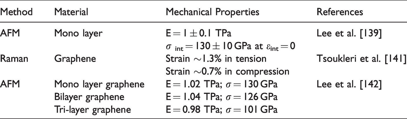
Graphene has a two-dimensional planar sheet structure and a hexagonal crystal lattice followed by covalent bonds between carbon atoms. Naturally, graphene is found in two forms: “monolayer” and “free-standing” [22]. Graphene owns some substantial mechanical properties like in-plane stiffness, high Young’s modulus, tensile strength, flexural strength because of the hexagonal 2-D crystal lattice consisting of sp2 hybridized C-C bonds. Monolayer graphene with defect-free is regarded to be a strong material yet [139]. However, it is worth mentioning that thermal and electronic transmission in graphene is very responsive to interruptions of the sp2-bonding network, but mechanical properties are substantially more tolerating of defects [140]. Table 2 shows some of the mechanical properties of graphene materials [143].
Mechanical properties of graphene material.
Thermal
The heat flow direction of graphene can be divided into in-plane and out-of-plane directions. In-plane heat flow is more prominent than out-of-plane, and it is formed because of covalent sp2 bonding among carbon molecules, while out of plane is emitted from feeble van der Waals coupling [144]. Graphene-based transistors are recipients of in-plane heat flow reliant on a specific network. The heat flow can be regulated by phonon scattering, interfaces, and edges. Eventually, the rare thermal properties of graphene come from its 2 D structure, creating a powerful area for new breakthroughs of heat-flow physics, and potentially taking the lead for thermal appliances. The expanded graphite was observed to be the most efficient, having an in-plane thermal conductivity of 6.7 Wm−1 K−1 in the ribbon sample containing 40 wt% graphite [145].
Graphene is used as fillers to increase thermal conductivity. The thermal conductivity of single-layer graphene at room temperature is in the range ∼3000–5300 Wm−1K−1 of the Raman G peak frequency [146]. Yu et al. demonstrated that few graphene layers were useful filler for epoxy composites. It improved the thermal conductivity by more than 3000% (at ∼25 vol % loading) integrating into epoxy and exhibited a thermal conductivity κ = 6.44 W/m K [147]. So, graphene sheets can perform like hurdles to inhibit heat generation propagation from the outer atmosphere in a polymer matrix and enhance thermal constancy. Balandin et al. [148] determined the thermal conductivity of single-layer graphene (SLG) by utilizing confocal micro-Raman spectroscopy. A schematic representation of the experimental setup and the subsequent Raman spectrum of SLG is illustrated in Figure 12.

(a) Illustrated the excitation laser light focused on a graphene layer suspended across a trench. (b) Raman spectrum with G peak region logged at two excitation power levels. (c) a shift in G peak spectral position shift versus power transfer; Reprinted with permission from [148].
Thermal conductivity is expressed as following equation (1) for plane heat wave case:
Where, h is the thickness of single-layer graphene. The intrinsic temperature 
Where δω is the small alter in peak position because of a shift in δP and is computed from the curve slope in Figure 12(c). Graphene temperature coefficient χG is −1.6 × 10⁻² cm−1/K. So, the thermal conductivity of single-layer graphene is from ∼4.8 × 10³ to ∼5.3 × 10³ W/mK on in average. Few layers of graphene (2 to 4 layers) by Raman Opto-thermal are found ∼2800 − 1300 W/mK [149].
Electrical
The distinctive atomic arrangement of the carbon atoms in graphene permits its electrons to easily move at exceedingly high velocity without the notable chance of scattering, conserving valuable energy typically lost in other conductors. Graphene can conduct electricity at the limit of zero mass carrier’s intensity since the electrons do not appear to slow down or localize [150]. The electrons of graphene behaved like a relativistic Dirac fermion system [151], a linear energy spectrum, and revealed some exceptional electronic properties such as the quantum Hall effect [152], absence of the Anderson localization [153]. Colloidal graphene quantum dots with chemically derived have been developed [154]. There are some critical properties as superior charge carrier mobility, ambipolar electric field effect [155], ballistic transport [156], chirality [157], weak scattering of charge carriers [158], and weak anti-localization [159]. Graphene has very high charge mobility because of the electronic arrangement ranging between 2000–15000 cm2 V−1S−1 [160]. The most remarkable phenomena observed in graphene are quantum Hall effects and substantial control of quantum interference effects. It was noted that the electrical properties of graphene can be linearly improved incorporating of free charge carriers such as dopants [161] and the charge carrier density.
Optical
The optoelectronic properties of graphene are entirely recognized and combined with the polymer matrix [162]. Graphene can be tuned with the ultra-wideband [163], zero bandgap and strong contact of Dirac Fermions with electromagnetic radiation [164]. Graphene can absorb 2.3% of the incident light at one atomic thickness [165]. The rare optical properties of graphene are produced by a conical band of the electrons and holes at the Dirac point. It shows also high optical transmittance, low optical reflectance, luminescence, photoluminescence [166], quenching properties, and fluorescence quenching capabilities [167] due to its distinct electronic structures [168]. Additionally, the opto-electrical characteristics of the graphene film are very responsive to its layer numbers [169] and do vary with the layer number. The more graphene layers produced the greater light absorption at the expense of the lower optical transparency. It was found that single-layer graphene has an optical transmittance of 97.4%, and this decreases linearly with the number of layers. The luminescence and photoluminescence properties of graphene are successfully being applied in various biological functions [170]. Moreover, the transparency of graphene increases from monolayer to few-layer graphene, which decreases its surface area [171].
Properties of graphene nanocomposites
Graphene improves the performance of polymer-based composites due to its high strength and high modulus properties [172]. Recently, it has become a novel class of nanofillers for resinous composites. There are some factors on which the properties of polymer/graphene composites depend on such as the filler’s dispersion, bonding amongst filler and matrix, filler to matrix ratio and the graphene sizes. It was reported that filler dispersion, size of filler, and the interfacial bonding between reinforcements and matrix are crucial aspects for the overall properties of the resultant composites [173]. Bhanuprakash et al. described that graphene oxide could improve the interfacial properties effectively between carbon fiber and epoxy and enhance the interlaminar shear strength by 47% of composites [174]. Structural features, morphology, weight fraction, rate of dispersion, modification of the surface, and interfacial bonding between graphene and polymer are the main parameters which influence the composite properties.
Mechanical properties
The studies on the mechanical properties of polymer/graphene nanocomposites revealed that resin modulus was improved with the addition of the graphene. Such as, the modulus of epoxy resin was improved about 31% by addition of the graphene platelet (0.1 wt%) [175]. Additionally, several researchers reported that the mechanical properties of nanocomposites were significantly improved with the addition of graphene nanoplatelets [176–179]. Numerous factors that manipulate the mechanical properties of graphene-associated materials as
Tensile
A number of experimental studies indicated that the evidence integration of graphene into the composites improves the tensile properties of the composites [184–186]. A short record of graphene epoxy nanocomposites studied in tensile properties values is presented in Table 3. Tang et al. [90] scrutinized the effect of graphene dispersion while Wang et al. [173] analyzed graphene nanoplatelet size impact on tensile, flexural modulus and strength of a graphene/epoxy nanocomposite. Yao et al. observed that when 0.8 wt % graphene was added to epoxy nanocomposites, the tensile strength and elongation at break increased by (37%) and (63%), respectively, as compared with neat epoxy [199]. Lee et al. [200] reported that functionalized graphene (0.1 wt%) improved the mechanical properties of epoxy composite compared to the pristine. Another study showed that epoxy with 1.5 vol.% GO enhanced the tensile strength, modulus and hardness of composite [25]. Tang et al. [187] studied surface functionalization of graphene oxide (GO) which was accomplished by refluxing GO with a diamine and polyetheramine. It was found that 2.7 vol% of functionalized GO/epoxy nanocomposites showed higher tensile modulus (536%) and strength (269%) compared to the pristine graphene/epoxy nanocomposites. It was identified that the mechanical properties of carbon fiber/epoxy/GO (0.2 wt.%) composites exhibited enhancement in the tensile strength, modulus, toughness, flexural strength by almost 34%, 20%, 83%, and 55%, compared to the neat composite, respectively [182]. The tensile strength and modulus of graphene oxide (1 wt.%) added epoxy composites were 29.2% and 22.0% higher than those of neat epoxy at a cryogenic temperature [184]. The inclusion of 0.25 wt% graphene nanoplatelets (GNPs) to epoxy nanocomposites showed the best improvement in tensile strength (20%) compared to the neat composite [176].
Tensile properties of graphene/epoxy nanocomposites.

GNPs: graphene nanoplatelets; GO: graphene oxide; f-GNPs: functionalized graphene nanoplatelets; G-P: Graphite platelet; f-Gr: functionalized graphene; f-GNR: functionalized graphene nanoribbon; f-GO: functionalized graphene oxide; RGO: reduced graphene oxide; TRGO: thermally reduced graphene oxide.
Flexural
Graphene nanoplatelets are found to be inexpensive and successfully applied as nanofillers to improve the flexural performance of the composites [201,202]. The larger surface area of GNPs increases the contact area with the matrix. It maximizes the stress transfer between the matrix and GNPs [203]. A summary of flexural properties of graphene/epoxy nanocomposites is presented in Table 4. GNPs addition (0.5%) in the resin increased the flexural modulus and toughness by 14% and 28% compared to the control, respectively [209]. Another study observed that GNPs coated carbon fiber/epoxy composite (0.25 wt%) improved the fatigue life of the neat composite [176]. Naebe et al. manufactured covalent functionalized epoxy/graphene nanocomposites and demonstrated 22% and 18% improvement in flexural strength and modulus, respectively, as illustrated in Figure 13 [204].
Flexural properties of graphene/epoxy nanocomposites.

GO: graphene oxide; GNPs: graphene nanoplatelets; f-GNPs: functionalized Graphene nanoplatelets; GNP: graphite nanoplatelet; f-Gr: functionalized graphene; f-GNR: functionalized graphene nanoribbon; CF: carbon fiber; VaRTM: vacuum-assisted resin transfer molding process; RTM: resin transfer molding.

(a) Stress–strain curves and (b) flexural modulus and strength of the various composite specimen; Reprinted with permission from [204].
Interlaminar shear strength (ILSS)
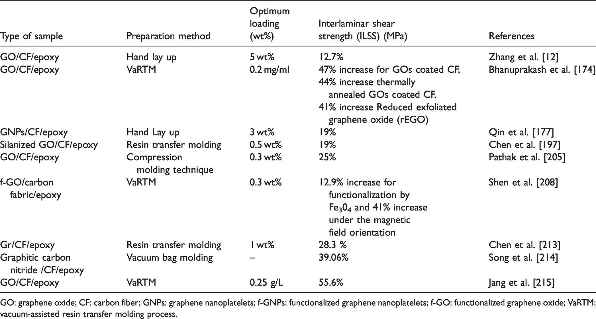
To determine the capability of a composite for resisting delamination damage, the interlaminar shear strength (ILSS) is considered as a critical parameter. Pathak et al. observed that the interlaminar shear strength (ILSS) of GO added (0.3%) carbon fiber/epoxy composites increased 25% compared to the pristine [205]. Zhang et al. [12] claimed that interlaminar shear strength (ILSS) was increased (12.7%) when GO sheets were added to the interfacial regions of carbon fiber/matrix composite. Another study reported that at 15 wt% of graphene oxide/polyaniline (60:1 weight ratio) in the carbon fiber/divinylbenzene/polyaniline, enhanced (76%) its ILSS properties [210]. Han et al. found that when the epoxy resin was loaded with 10 wt% GO, the interlaminar shear strength (ILSS) was improved (8.05%) [211]. Shen et al. [208] reported that the interlaminar shear strength (ILSS) of a carbon fabric/epoxy composite was enhanced (12.9%) by the optimal content of oriented GO (catalyst Fe3O4) as depicted in Figure 14. Qi et al. [212] studied the grafting of stiff p-phenylenediamine (PPD) and ethylenediamine (EDA) to the carbon fiber surface. For the grafted EDA and PPD carbon fibers, the ILSS properties were improved by 44.8% and 38.6%, respectively. The interlaminar shear strength (ILSS) of various graphene epoxy nanocomposites is presented in Table 5.
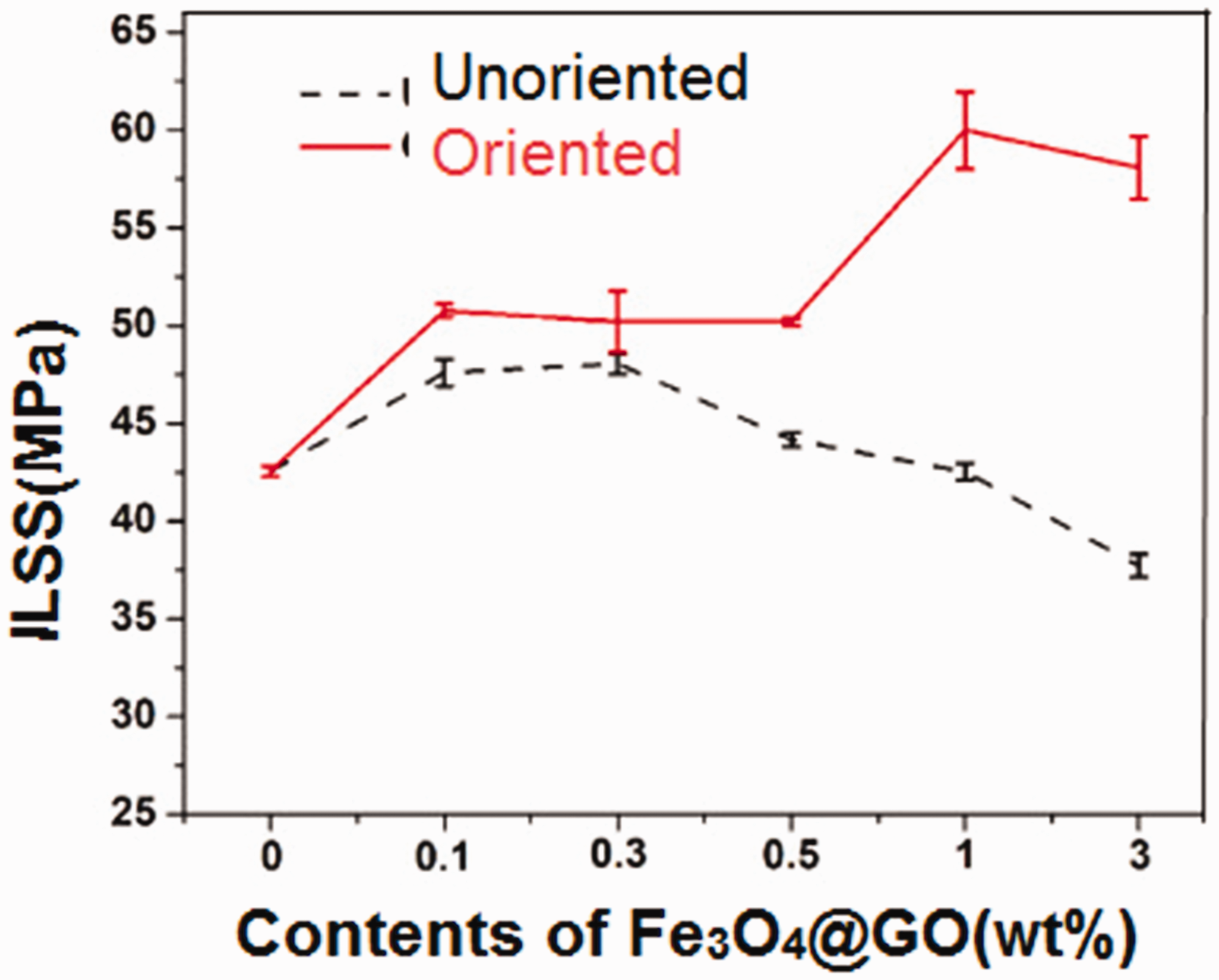
Effect of orientation and contents of GO (catalyst Fe3O4) on the interlaminar shear strength of carbon fiber/epoxy composites; Reprinted with permission from [208].
Interlaminar shear strength (ILSS) of various graphene epoxy nanocomposites.
GO: graphene oxide; CF: carbon fiber; GNPs: graphene nanoplatelets; f-GNPs: functionalized graphene nanoplatelets; f-GO: functionalized graphene oxide; VaRTM: vacuum-assisted resin transfer molding process.
Interfacial shear strength (IFSS)
Interfacial shear strength (IFSS) between particle and matrix in nanocomposite is crucial property which influenced the fracture toughness of composite [215]. Numerous researchers modified fiber surfaces to enhance the interfacial shear strength of fiber composites by using various nanoscale surfactants such as carbon nanotubes and graphene [216]. Yao et al. explained that by designing the fiber/matrix interface, the addition of nanomaterials improved the interfacial properties of the carbon fiber/epoxy composites [28]. Chen et al. [197] studied silanized graphene oxide on fiber surfaces by employing physical deposition to form gradient interphase in the composite interface. The addition of 0.5 wt% silanized graphene oxide in composite enhanced the interfacial shear strength (60%), as shown in Figure 15. Zhang et al. [12] improved the interfacial properties of carbon fiber/epoxy composites by dispersing GO sheets (5 wt.%) in the fiber sizing. Beggs et al. [217] examined an aryl diazo-grafting methodology by applying reagent concentrations to modify of carbon fiber surfaces. A substantial rise in IFSS was noted in the resultant composites. Table 6 shows the interfacial shear strength of various graphene/epoxy nanocomposites.
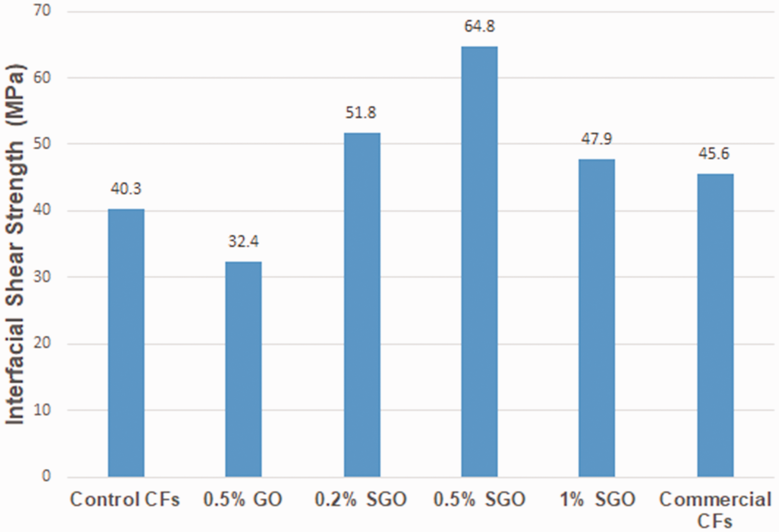
Interfacial shear strength (IFSS) of carbon fiber/epoxy composites with graphene nanosheets; Reprinted with permission from [197].
Interfacial shear strength of various graphene epoxy nanocomposites.

GO: graphene oxide; CF: carbon fiber; GrNp: graphite nanoparticle; f-Graphite: functionalized graphite; CF-ECO: carbon fiber of electrical conduction; VaRTM= vacuum-assisted resin transfer molding technique.
Interlaminar fracture toughness
Mode-I fracture toughness (GIC)
The fracture behavior of the composites was affected by fiber sizing/coating, modification of matrix, fiber volume fraction, and stacking sequence [219]. Fracture toughness is an essential factor as it allows defining the energy absorption and damaging tolerance capability of a structure [220]. It was reported that graphene and its derivatives were more efficient for increasing mode-I fracture toughness of epoxy resin than carbon nanotube-incorporate epoxy resins [221]. The mode-I fracture toughness of the graphene/epoxy nanocomposite was improved (53%) compared to the MWCNTs composite [175]. It was identified that at 1 wt % loading of graphene oxide to an epoxy resin enhances its mode-I fracture toughness (28-111%) [18]. One of the another studies showed that mode-I fracture toughness (GIC) was enhanced from 0.165 kJ/m2 to 0.336 kJ/m2 for a nanocomposite containing 0.5 wt.% of GNPs [222]. Galpaya et al. [223] observed that mode-I fracture toughness was improved about 50% with 0.1 wt. % GO loading to the epoxy. On the other hand, introducing functionalized graphene sheets in epoxy matrix increased its fracture toughness, fracture energy, and fatigue resistance, as illustrated in Figure 16 [224]. It is stated that fiber/matrix adhesion improvement by fiber surface treatment or sizing incorporated with graphene nanoplatelets resulted the improvement of mode-I and mode-II fracture toughness, interlaminar shear strength, and in-plane shear strength of the composites [225]. Another study reported that functionalization of graphene enhanced mode-1 fracture toughness of composites [200]. Figure 17 shows the graphene nanocomposites with the -COOH and -NH2 functional groups and NH2 functional group-containing graphene, which offered better fracture toughness compared to the -COOH functional group [200]. Table 7 shows the fracture toughness of various graphene/epoxy nanocomposites.

Effect of various GNPs contents on fracture toughness and fracture energy of nanocomposites; Reprinted with permission from [224].

Fracture toughness (mode I) of graphene/epoxy nanocomposites with different graphene loadings; Reprinted with permission from [200].
Fracture toughness of various graphene/epoxy nanocomposites.

GO: graphene oxide; GNPs: graphene nanoplatelets; f-GNPs: functionalized graphene nanoplatelets; CF: carbon fiber; VaRTM: vacuum-assisted resin transfer molding technique; f-GNR: functionalized graphene nanoribbon; RGO: reduced graphene oxide; GWF: graphene woven fiber.
Mode-II fracture toughness (GIIC)
It was found that at 0.5 wt%, loadings of graphene nanoplatelets to epoxy exhibited a 41% enhancement on mode-II fracture toughness of graphene nanocomposite compared to the neat epoxy adhesive as shown in Figure 18 [229]. Domun et al. noticed that the fracture toughness of epoxy resin was enhanced by over 50% with the inclusion of 0.25 wt% addition plasma functionalized graphene nanoplatelets compared to the neat epoxy [228].

Mode-II fracture toughness of graphene nanocomposites at different nano graphene content; Reprinted with permission from [229].
Thermal conductivity
Polymer composites possess poor thermal conductivity, and it has been a significant drawback of their end-use, especially in high performance required areas such as aerospace and defense. Graphene nanocomposites grip huge potentiality like the thermal interface materials (TIMs) for dissipating heat for electronic packages [230]. Graphene-associated material is a good candidate for generating advanced functional materials [231]. The thermal conductivity is calculating corresponding to the following equation (3):
Where K is the thermal conductivity (W m−1K−1), α is the thermal diffusivity (mm2 s−1), ρ is the density of the samples (gcm−3), and

An illustration of thermal conductivity of MWCNTs/epoxy, graphene/epoxy, and Py-PGMA–graphene; Reprinted with permission from [238].
Thermal conductivity enhancement by various graphene/epoxy nanocomposites.

GNPs: Graphene nanoplatelets; MGO: Modified graphene oxides; GO: Graphene oxide; GNp: Graphite nanoparticle; f-GNS: Functionalized graphene nanosheets.
Electrical conductivity
When graphene is used as filler to the polymer matrix, it improves the electrical conductivity of the composite because of its good conductivity and aspect ratio. A conductive network is formed in the polymer matrix when graphene is added. The conductivity is expressed as a function σc filler loading can be termed by employing an easy power-law expression, i.e.,
Where σc is the volume fraction of the filler, φc is the percolation threshold, σf is the conductivity of the filler, and t is a scaling exponent. Electrical functioning relies on some factors such as the processing and dispersion, inherent features of the filler, aggregation, and filler orientation and alignment [243]. Stankovich et al. [244] made graphene-based conductive polymer nanocomposites altered with isocyanate and reduced by hydrazine hydrate process made graphene to show good electrical conductivity. It was shown that the percolation threshold value was only 0.1 vol%, near to the lowest value of the single-walled carbon nanotube which is sufficient for many electrical applications. Improvement of the electrical conductivity of epoxy from 4.3x10⁻¹⁵ to 2.6x10⁻⁶ S/m at the percolation threshold of graphene was 1.0 wt% [195]. At 5 mg/ml of graphene concentration, the electrical conductivity reached 0.70 S/cm, achieving orders of magnitude enhancement of the carbon/epoxy nanocomposites as depicted in Figure 20 [245]. Table 9 presents the electrical conductivity of various graphene/epoxy nanocomposites.

The electrical conductivity of carbon foam/epoxy/reduced graphene oxide and melamine foam modified graphene oxide/epoxy composites with different GO concentration; Reprinted with permission from [245].
Electrical conductivity of various graphene/epoxy nanocomposites.
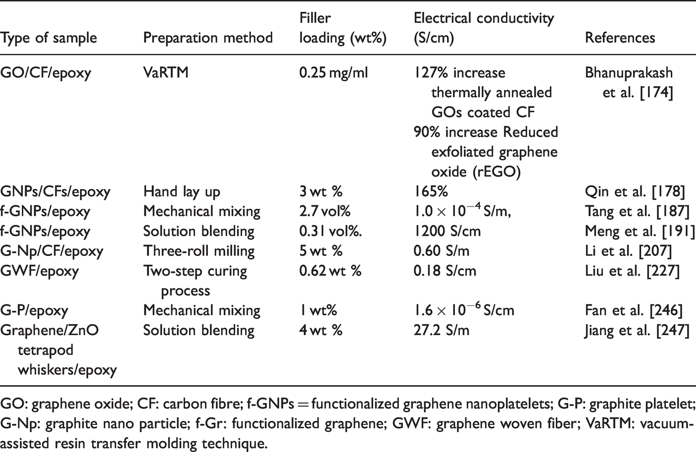
GO: graphene oxide; CF: carbon fibre; f-GNPs = functionalized graphene nanoplatelets; G-P: graphite platelet; G-Np: graphite nano particle; f-Gr: functionalized graphene; GWF: graphene woven fiber; VaRTM: vacuum-assisted resin transfer molding technique.
Application areas of graphene and graphene nanocomposites
Graphene can be employed in a broad range of areas comprising engineering, electronics, medicine, energy storage, industrial, household design, biomedical applications, drug delivery and tissue engineering [248,249]. Some of the potential end-uses of nanographene composites were provided in this section.
Industrial structural components
Graphene integrated fiber-reinforced composites is one of the candidate for structural materials in the aviation and automotive industries. Recently, graphene is used for the Airbus A350 horizontal tail leading edge. Graphene increases the mechanical properties of the leading edge, enabling plane parts lighter and thinner, enhanced aerodynamics, and reduces the consumption of fuel across the lifespan of the airplane. Carbon fiber-reinforced graphene nanocomposites have numerous applications, for example, improved gas barrier properties, surface technology, fuel tank and protective coating in the aerospace industry [1,139]. The automotive industry worldwide is faced with the challenges of carbon dioxides emissions reduction, safety, and energy efficiency. Graphene-based composite materials can be used for energy-efficient and safe vehicles (EESVs) [250]. Introducing graphene-based smart devices (combined with wirings, sensors, switches), transparent heaters defogging/deicing systems in the automotive areas are predictable to reduce fuel consumption and subsequently the CO2 emission at various stages [251]. The greatest effect will be in the upcoming future is in the construction area by adding graphene to concrete.
Electronics
Graphene is a material with several exceptional characteristics and can establish the next generation of electronics smarter transistors, semiconductors, bendable phones, and other electronics. Graphene's exclusive properties of lightest, strongest, and higher conductivity have led to research into its applications as semiconductors [252]. Graphene has novel functionalities, including ultracapacitors [253], transparent conducting electrodes [81], optical displays, printing circuits and electrical devices [254]. Generally, graphene nanoribbons (GNRs) provide field-effect transistor (FET) applications with very high electrical conductivity and flexibility [255]. Graphene and its derivatives are widely employed in light-emitting diode (LED), FET, memory, and photovoltaic devices [256], electroluminescent devices, gate dielectrics [257], and touch panel devices. There is a great concern in the commercial adaptation of highly electrical quality for electronics applications of large-area graphene, involving high-frequency terahertz (THz) electronics [258] and transparent and resilient electrodes for touchscreen displays and solar cells [259]. Graphene nanocomposite actuators are employed in the micro-electro-mechanical system (MEMS)-based micro-grippers [260], photonic switches, soft robotics, plastic motors, and adaptive micro-mirrors [261]. One of the example is that bilayer actuator made with 30 wt% graphene composites is used to construct a beluga whale soft robot [262].
Energy storage
Graphene-based nanocomposites can be used to replace traditional rechargeable lithium batteries in energy storage applications because they can retain energy and power density [263]. In the last decades, rigorous research has been going on to implement Li+ ions into the lattice of graphite, and recently, electrochemical energy storage capacity in graphene-based systems attains much attention for research [264]. Graphene supercapacitors can be charged very rapidly, capable of storing a vast quantity of electricity. Lithium-ion batteries incorporating graphene could be employed as electrically powered vehicles in smartphones, laptops but at a minimal size and weight.
Sensors
Graphene-based e-textile have been used as sensors for various purposes such as electrodes for heart rate monitoring, strain sensor, alcohol sensor, glucose sensor, CO2 and NO2 gas sensor, and temperature sensors [265,266]. The GO-based fabric has been used as wearable gas and alcohol vapors sensors and exhibited promising results [267]. Graphene-reinforced polymer-based composite biosensors benefit due to higher sensitivity, speedy response time, permanency, and a low limit of detection (LOD) [268]. The monitoring, informing, and prompt detection of toxic gases [269] become more prevalent to avoid or lessen accidents that involve poisoning and blasts. Graphene-reinforced polymer nanocomposite material can be used for various sensor applications (e.g., temperature, biomolecules, pressure, pH, and strain sensors) owing to their 2 D (atom-thick) conjugated structures, higher conductivity, and larger surface areas [270].
Biomedical
Graphene nanocomposites have been drawn attention to the biomedical field. Recent advancement of graphene in biomedical applications gives us several biomedical gadgets, for example, deep brain stimulators [271] and blood glucose sensors [272]. In addition, graphene has been used as a nanomaterial in tissue engineering [273], gene therapy [274], cancer treatment and diagnosis [275], cell imaging [276], and bioelectronics [277]. The antimicrobial activity and drug delivery potential of the graphene nanocomposite have been also discovered. Graphene has been applied with polystyrene, nylon-6,6, polyurethanes, poly(caprolactone) and poly (methyl methacrylate) in the biomedical field [278]. The application of graphene in this area has prominence on the skillful treating methods to construct the preferred structures and membranes.
Textile industries
Graphene is a promising aspirant as the functional element in smart textiles, including wearable e-textiles, due to its superior properties and its integration into synthetic and natural textiles that can be utilized for the groundwork of multifunctional textiles for larger applications [279]. By modifying the fabrics with graphene can enhance properties like mechanical strength, antibacterial, flame resistance, photocatalytic, conductivity, and UV protection of the fabric and be used as protective clothing for healthcare workers, firefighters, laborers, and military personnel [280]. Several attempts have been made to mingle textile-based sensors into clothes, such as inkjet-printed graphene composite inks for wearable textiles applications that offer mass customization, lessening material waste, high precision printing, and compatibility with various substrates [281]. Gao et al. [282] developed porous activate cotton textile (ACT) tubular fibers embedded with NiS2 nanobowls and coated with graphene to prepare flexible electrodes for Li-ions batteries and show its practical application for flexible energy storage devices. Lu et al. [283] prepared highly conductive graphene-coated silk fabrics (sheet resistance is 1.5 kΩsq−1), and fibers (the electrical conductivity is 3595 Sm−1) that are promising as the functional supporting matrix and conducting fabrics/wires in future wearable electronics. Another study explored the fabrication of electroconductive cotton textiles by using graphene, and these fabrics have high potential to apply in advanced applications such as smart e-textiles [284]. Tang et al. [285] fabricated multifunctional cotton fabric with high electrical conductivity and ultra-strong UV radiation protection properties using polyaniline (PANI)-GO nanocomposites. Conclusively, it is identified that graphene nanocomposites show significant advantages in the textile area and shine a bright light on the fabrication of functional textiles.
Conclusion
In this paper, graphene and graphene nanocomposites were reviewed. The synthesis process of graphene and their fabrication, properties, performance, and potential applications have been identified.
It was found that several synthesis methods for nanographene were developed as mechanical exfoliation, liquid-phase exfoliation, chemical vapor deposition, and epitaxial growth. On the other hand, the fabrication of graphene-based nanocomposites includes solution mixing technique, in-situ polymerization, melt blending, and electrospinning. In addition, fabrication methods on nanographene dispersed fiber/matrix composites includes resin transfer molding and vacuum-assisted resin transfer molding.
The growth of graphene/matrix and fiber/matrix graphene nanocomposites opens a new paradigm where matrix and fiber can be modified to upsurge the properties of advanced composites. The critical properties of graphene added nanocomposites were discussed. These include in-plane and out-of-plane thermo-mechanical, electrical, and optical properties. It was realized that graphene and graphene nanocomposites represented potential materials in advanced engineering applications, including soft robotics, microelectronics, energy storage, supercapacitor, transparent electrodes, biological and biomedical areas, biosensors and wearable e-textiles.
Future research probably carries on the defect-free 2 D graphene plate, surface functionalization of nanographene to improve the structure-property interaction of nanocomposite and cost-effective fabrication techniques.
Footnotes
Declaration of conflicting interests
The author(s) declared no potential conflicts of interest with respect to the research, authorship, and/or publication of this article.
Funding
The author(s) received no financial support for the research, authorship, and/or publication of this article.