
Abstract
In this paper, biaxial warp-knitted fabrics were produced with different high tenacity polyester linear density and inserted yarns density. The low-velocity impact property of flexible composites made of polyurethane as matrix and biaxial warp-knitted fabric as reinforcement has been investigated. The effect of impactor shape and initial impact energy on the impact response of flexible composite is tested. The results show that the initial impact energy have minor effect on the impact response of the biaxial warp-knitted flexible composites. The impact resistance of flexible composite specimen increases with the increase of high tenacity polyester linear density and inserted yarns density. The damage morphology of flexible composite materials is completely different under different impactor shapes. The findings have theoretical and practical significance for the applications of biaxial warp-knitted flexible composite.
Introduction
Membrane structure had become one of the important structural systems in modern space structures. In the field of construction, membrane structure materials had been widely used in large-span space structures due to their huge ductility [1]. There were two types of membrane materials, including coated fabrics and thermoplastic compounds [2]. Flexible textile composites could be used as the main component of the coated fabrics, which was composed of different layers combined with matrix, reinforcement and coating. In addition, it had great potential in aerospace [3,4], construction [5–7] and engineering applications due to their advantages of high production efficiency, light weight and high convenience [8]. Different structural and reinforcement materials of flexible textile composites might lead to complex mechanical responses. It was very essential to investigate the mechanical properties of flexible textile composites from the perspective of the promotion and development of building materials.
The mechanical properties of flexible textile composites had been studied on the basis of the uniaxial tensile tests, biaxial tensile tests, shearing tests, etc. [1,9–12]. The mechanical properties of flexible textile composites were different from traditional building materials due to complex compositions. Flexible textile composites performed strongly nonlinear characteristics and anisotropic behavior. Zhang et al. [13] studied the effect of initial notch shape, initial notch size, sample size, and loading rate on the center tearing behavior of PVC-coated fabrics with initial notches. The result showed that the tearing strength of PVC-coated fabrics with initial notches was significantly reduced. The effect of sample size, initial notch shape and loading rate on tearing failure mode was not obvious. Xu et al. [14] proposed a constitutive model of coated fabrics, which could predict the failure mode and tensile strength. Lin et al. [15] analyzed the tensile strength, peel load and static puncture resistance of flexible composites. The results showed that the flexible composites composed of Kevlar fabric and polyurethane board had stable structure and excellent mechanical performance. Hu et al. [16] found the uniaxial tensile properties of enhanced plain woven fabrics were stable in all directions. And the failure mechanism of uniaxial monotonic tensile tests and uniaxial cyclic tensile tests was analyzed.
The above research results on nonlinear characteristics further improved the engineering value of flexible textile composite. Flexible textile composite would be affected by external environment debris under the action of external wind loads, which might cause damage to the flexible textile composite in the external application environment. Therefore, it was necessary to deeply understand the mechanical properties and failure mechanism of flexible composites under out-of-plane loads. Chen et al. [17] discussed the effects of impact velocity, impact location, fabric pretension force and boundary condition on the penetration resistance capacity. The failure modes of specimens were compared under various impact conditions. This study had found that the vulnerability of composite subjected to the impact was significantly affected by the pretension force of fabric and boundary condition. Bandaru et al. [18] found the stacking order of composite materials had great influence on impact performance. Kevlar composite laminates was manufactured with eight layers Kevlar fabrics, H-1 composite laminates was manufactured with alternately stacking of basalt and Kevlar fabrics, H-2 composite laminates was manufactured with four layers Kevlar fabrics and four layers basalt fabrics. The results showed that impact resistance of H-1 composite laminates was better than Kevlar composite laminates and H-2 composite laminates. Unreasonable stacking order would even reduce the impact resistance of composite materials. Piotr et al. [19] investigated blunt trauma resistance of reinforcement fabrics including woven fabrics, unidirectional laminates and multi-axial fabrics. The ability of resist impact was measured by comparing the depth of the depression and the energy transferred to the backing material. Huang et al. [20] explored the effect on the static-bursting and low-velocity impact property of the sandwich foam flexible composites. The experimental results showed that the three-dimensional flexible composite material filled with polyurethane foam greatly improved its impact resistance. Mahesh et al. [21] observed low-velocity impact behaviour of flexible biocomposite laminates with different stacking sequences under different impact energy levels. They found that the flexible composites with jute/rubber/jute/rubber/jute (JRJRJ) had better impact resistance. And there was no delamination in the flexible biocomposite laminates. Wu et al. [22] presented a new type of flexible sandwich composite with core by shear thickening fluid (STF). They investigated the effects of thickness and STF volume on low-velocity impact behavior. Higher composite thickness and STF volume were beneficial to the energy absorption of composites. Al-Kinani et al. [23] found punches with different shapes were one of the key factors affected the damage mechanism of glass fiber/aramid fiber hybrid reinforced composites. Mitrevski et al. [24] investigated the effects of hemispherical, ogival and conical impactors on E-glass/polyester laminates. It had found that the peak force was highest for the hemispherical impactor. The specimens impacted by the conical impactor had highest contact duration and absorbed energy. The factors influenced low-velocity impact performance include the material properties of fabric, structure of fabric, punch geometry and velocity, thickness, etc.
There had been studies on the mechanical properties of sandwich foam materials and flexible composite materials under out-of-plane loads. However, there was a lack of further research on the low-velocity impact property of composites, which would be composed of biaxial warp-knitted fabric and flexible matrix. In this paper, the research aimed to investigate damage mechanism of biaxial warp-knitted flexible composite materials under low-velocity impact. The influence of initial impact energy, filament linear density, yarns density and impactor shapes on the impact resistance of biaxial warp-knitted composites were studied. It provides a reference for the structural design of the lattice structure inflatable membrane material.
Materials and experiments
Materials
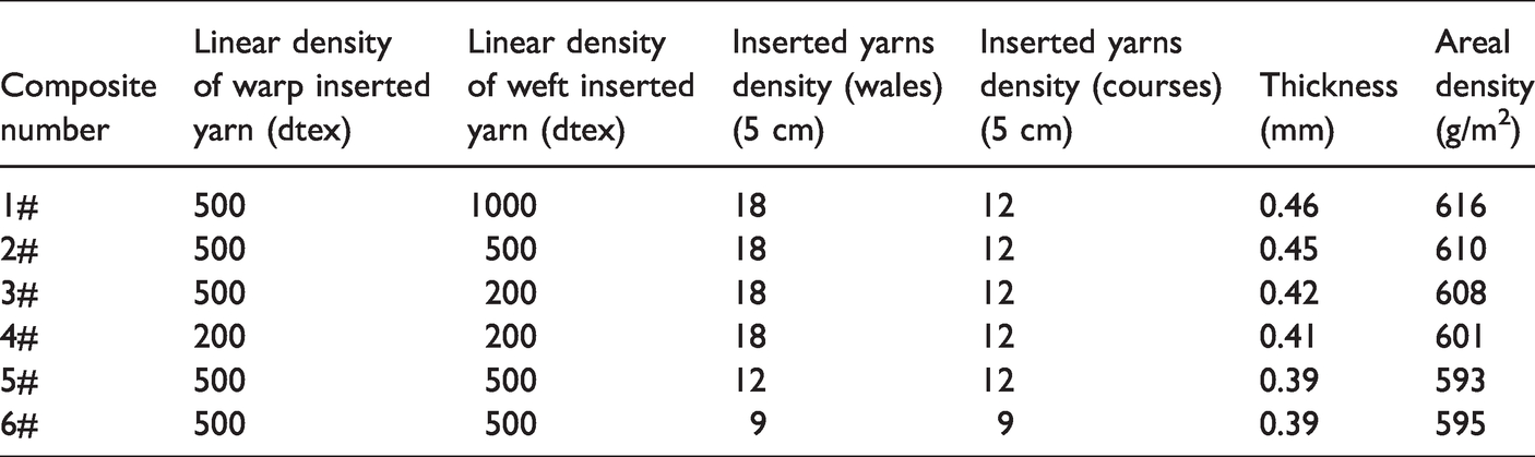
The biaxial warp-knitted flexible composites (supplied by Yuli Knitting Co. Ltd in Zhejiang, China) were shown in Figure 1(a). The biaxial warp-knitted fabrics were produced with 75dtex/24f polyester and high tenacity polyester on the warp-knitting machine RS3MSUS (Karl Mayer (China) Ltd. In Jiangsu, China) gauge E18 equipped with 2 guide bars (GB). The structure model of biaxial warp-knitted fabrics is shown in Figure 1(b). The structures of biaxial warp-knitted fabric are shown in Table 1. The guide bar 1(GB1) binds the warp insertion yarns and weft insertion yarns. Guide bar 2(GB2) inserted high tenacity polyester in the warp direction. Different types of biaxial warp-knitted flexible composites were fabricated followed by a hot-press procedure. Finally, one layer of biaxial warp-knitted fabric and two layers of PU film were hot-pressed together under compression using a plate curing machine. The structure of biaxial warp-knitted flexible composite is shown in Figure 1(c). Sample parameters of biaxial warp-knitted flexible composite are shown in Table 2.

Biaxial warp-knitted flexible composite (a) the image of biaxial warp-knitted flexible composite; (b) structure model of biaxial warp-knitted fabric; (c) the structure of biaxial warp-knitted flexible composite.
Structure of biaxial warp-knitted fabric.

Sample parameter of biaxial warp-knitted flexible composite.
Low-velocity impact testing
Low-velocity impact tests are carried on a drop-weight impact tester STLH-300 device (Jinan Shangtai Test Instrument Co., Ltd) as shown in Figure 2(a). The flexible composite material could be cut into circular specimens with a diameter of 11 cm. As shown in Figure 2(b), the sample was fixed on the fixture.

(a) Photographs of STLH-300 tester; (b) geometric dimension of fixture, impactor and composite sample.
The impactor consists of three parts, pressure sensor, impact lever and replaceable punch. Three steel punch of tester was conical-nosed punch, hemispherical-nosed punch and flat-nosed punch with 16 mm in diameter. Three kinds shape of punches are shown in Figure 3(a) to (c).The total impactor assembly mass is 6.141 kg and the pressure sensor can be reached to a maximum load of 30 kN. The impact energy of 6.9 J, 12.3 J, 19.2 J and 27.6 J was chosen to evaluate the low-velocity impact behaviors of flexible composite. The punch was released and dropped along a vertically guided path into the composite during the test process. The tests were conducted in an environment of 20 °C and a relative humidity of 65%. All parameters of impact tests are listed in Table 3.
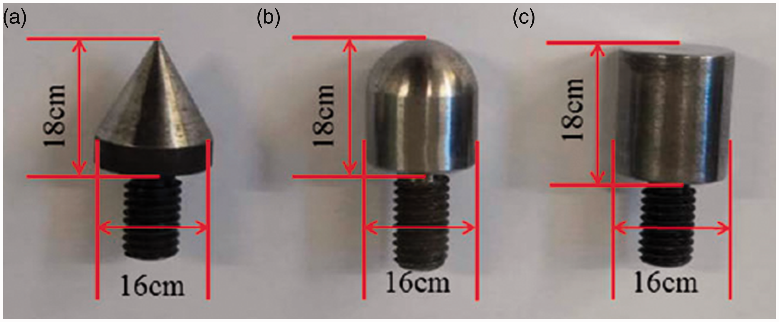
Three kinds shape of punches (a) conical-nosed punch; (b) hemispherical-nosed punch, and (c) flat-nosed punch.
Parameters of impact tests.

The damage morphology of biaxial warp-knitted flexible composite
Ultra-depth three-dimensional (3D) microscopy
The optical images of impact region morphology were taken by ultra-depth three-dimensional microscope (VHX-5000, KEYENCE, Japan) under the condition of hard light, which enable to investigate the failure modes of the sample.
Scanning electron microscopy (SEM)
Before carrying out the SEM analysis, the damaged specimens were sliced in the cross-section. The specimens were fixed on a metal sample stage with a conductive tape for gold spraying. SU510 type scanning electron microscope (Hitachi, Ltd., Japan) was selected to observe deformation and failure behavior of the flexible composites under 12.3 J.
Results and analysis
Effects of different initial impact energy on low-velocity impact properties
The punch of tester was hemispherical-nosed in the low-velocity impact test. Figure 4 shows the cross section of the woven structure fabric and oriented structure fabric. Schematic diagram of yarn force is shown in Figure 4(a) and (b). Since the warp and weft yarns are interwoven from top to bottom, the bending of the yarn occurs in woven fabrics before low-velocity impact. If the strength of the yarn is P, the yarn strength can be used to resist impact is F2 (F2 = Pist im) in woven structure fabrics. The yarn must overcome its own bending and straighten under the action of own force. In orientation structure of the biaxial warp-knitted flexible composite, the warp and weft yarns are distributed vertically. The yarn strength can be used to resist impact is F (F = P) in the biaxial warp-knitted fabrics. The orientation structure of the biaxial fabric can avoid own bending of the yarn to the greatest extent. The loss of yarn strength can be avoided, and the strength of yarns can be utilized to the greatest possible extent. The impact resistance of biaxial warp-knitted flexible composites would be better in theory.

Schematic diagram of yarn force in (a) woven structure; (b) orientation structure of the biaxial warp-knitted flexible composite.
In the low-velocity impact process of biaxial warp-knitted flexible composite, the drop weight of fixed mass and height is in the state of free falling state, and the potential energy of gravity is converted into kinetic energy. When the punch contacts the surface of the sample, the impact velocity of the drop weight reaches the maximum value. The impact process could be divided into three stages basically [25]. First of all, the energy of the punch is absorbed by deformation of the matrix on the biaxial warp-knitted flexible composite. Then, it is absorbed by the material deformation of the biaxial warp-knitted fabric. Finally, the impact energy absorption of biaxial warp-knitted flexible composite reaches the ultimate value when both types of deformation reach the limitation. The surface of the biaxial warp-knitted flexible composite is damaged. The punch rebounds and the remaining energy is transformed into upward kinetic energy. The punch is captured by the anti-second impact device, and the impact process finished.
Load-time curves of composite 1# under initial impact energy of 6.9 J, 12.3 J, 19.2 J, 27.6 J are shown in Figure 5(a). It can be seen that the composite 1# under the initial impact energy of 27.6 J has the largest slope of the impact load-time curve, followed by the composite 1# under the initial impact energy of 19.2 J, 12.3 J and the initial impact energy of 6.9 J has the smallest slope of the impact load-time curve. The time obtained peak impact load is around 10 ms in the 6.9 J impact energy, 7 ms in the 12.3 J impact energy, 5.3 ms in the 19.2 J and 3.7 ms in the 27.6 J. It can be concluded that the acceleration rate of the impact load increases with the increase of the initial impact energy. Energy absorption–time curves of composite 1# are shown in Figure 5(b). The result shows that the energy absorption of the flexible composites is not much different with different initial impact energy. The initial impact energy has minor effect on the impact resistance of the flexible composite under low-velocity impact. After the energy of 12.3 J, the peak impact load of the sample shows a slight downward trend. Therefore, the most commonly impact energy of 12.3 J was chosen to the subsequent experiment. The images of composites 1# after low-velocity impact tests with different initial impact energy are shown in Figure 5(c) to (f). It is obvious that the damage morphology of flexible composite 1 # is basically elliptical and the main part of the composite 1 # in contact with the punch formed a crack after the test. The composite 1 # was destroyed under the impact-tensile load of hemispherical-nosed punch. Due to the thin surface matrix thickness of the biaxial warp-knitted flexible composite, the matrix and the reinforcement were completely destroyed after reaching the maximum energy in the process of the low-velocity impact. Even if the impact energy is increased, the peak impact load of the sample cannot continue to increase.

(a) Load-time curve of composite 1# under different initial impact energy; (b) energy absorption–time curves of composite 1# under different initial impact energy; (c)–(f) the damage images of composites 1# after impact test.
Effects of different high tenacity polyester linear density on low-velocity impact properties
The high tenacity polyesters linear density of composite 1# (500dtex × 1000dtex), 2# (500dtex × 500dtex), 3# (200dtex × 500dtex), 4# (200dtex × 200dtex)with same inserted yarns density (18 × 12) are shown in Table 2. The tester was equipped with a hemispherical-nosed punch. Load-time curves of four samples (1#, 2#, 3#, 4#) with different linear density are shown in Figure 6(a). It is obvious that the peak impact loads of flexible composites with different high tenacity polyester linear density have remarkable difference under the same initial impact energy. The composite 1#, composite 2#, composite 3# and composite 4# having maximum impact load of 730 N, 640 N, 330 N and 270 N respectively. Because the higher linear density would slow down the failure process of composites, the higher time is obtained .The damage time of flexible composite specimen decreased with the decrease of peak load. The absorption–time curves of four samples with different linear density are shown in Figure 6(b). It was indicated the initial variation trend of four samples was similar, and the energy absorption of flexible composite specimen increases with the increase of high tenacity polyester linear density.
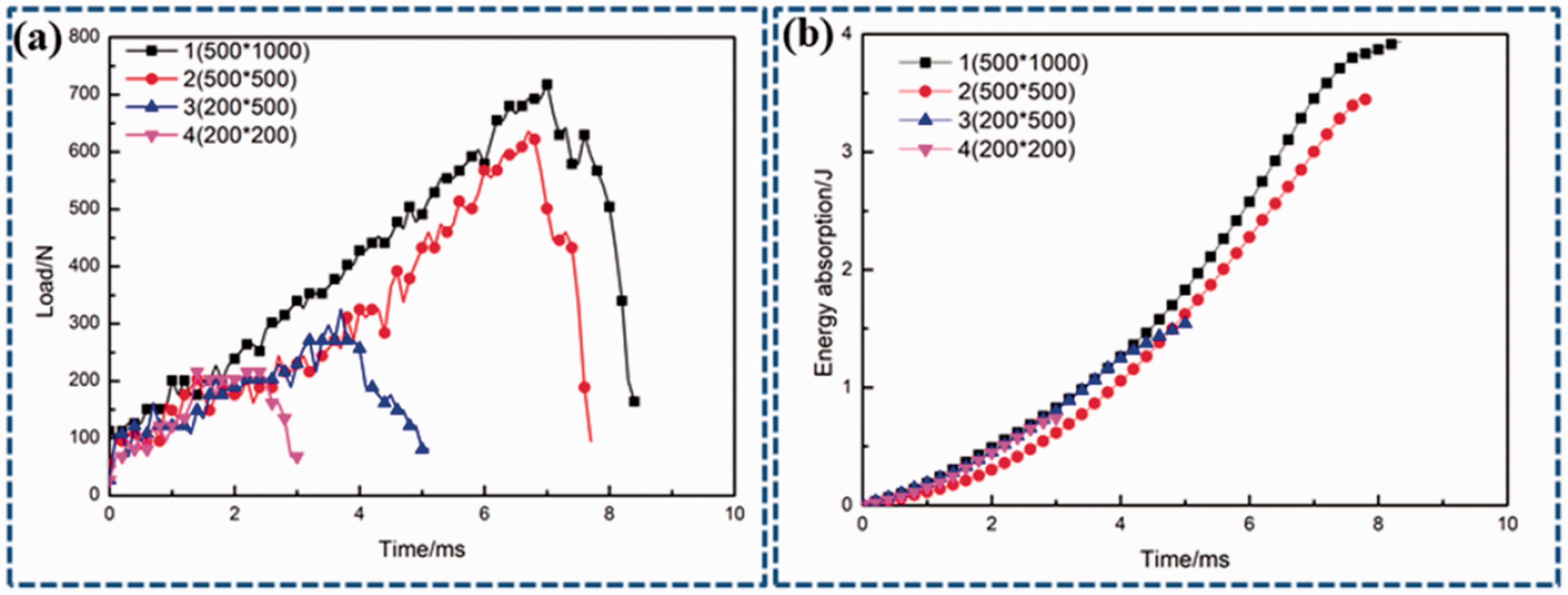
(a) Load-time curve of four samples with different linear density; (b) energy absorption–time curves of four samples with different linear density.
The biaxial warp-knitted flexible composite deforms from the impact point when the impact occurs. The impact load is concentrated at the point of impact. With transfer of stress wave, the flexible matrix on the surface of the sample was damaged. The pulling and fracture of fiber become the main ways to further absorb part of the impact energy. When the quantity of impact area yarns remains identical, the impact resistance of the sample will be enhanced with the increase of the high tenacity polyester linear density. In addition, it can be seen from Figure 6(a) that the load-time curves of all biaxial warp knitted fabric flexible composites show violent fluctuations. The fluctuation of load-time curve is formed by the interaction between the vibration of the drop hammer impact device and the high stiffness of the biaxial warp-knitted flexible composite.
Effects of different inserted yarns density on low-velocity impact properties
The inserted yarns density of composite 2# (18 × 12), 5# (12 × 12), 6# (9 × 9) with same high tenacity polyesters (500 dtex × 500 dtex) are shown in Table 2. The punch of tester was hemispherical-nosed in the test. Load-time curves of three samples(2#, 5#, 6#) with different inserted yarns density are shown in Figure 7(a), which shows that peak load of flexible composite 2# has the largest value, followed by flexible composite 5# and lastly flexible composite 6#. Energy absorption–time curves of three samples with different inserted yarns density are shown in Figure 7(b). It is concluded that composite 2# can absorb more energy under same initial impact energy. As the number of inserted yarns density increases, the energy absorption also increases.

(a) Load-time curve of three samples with different inserted yarns density; (b) energy absorption–time curves of three samples with different inserted yarns density.
The main reason for this phenomenon is that the increase of inserted yarns density may leads to yarns number of per unit area increase. And yarns number of per unit area increase will increase the force per area of the flexible composite. Composite reinforced by biaxial warp-knitted fabric with higher inserted yarns density would have more compact immanent structure. Therefore, the impact performance of the biaxial warp-knitted flexible composite was improved.
Effects of different impactor shapes on low-velocity impact properties
Load-time curves of flexible composite (1#, 2#, 3#, 5#, 6#) with different punches are shown in Figure 8(a) to (e). It can be seen that the peak impact load with flat-nosed punch is the largest, followed by the hemispherical-nosed punch, and the conical-nosed punch is the smallest. The flat-nosed has the largest contact area with the flexible composite, so there are a host of yarns in the impact area. The impact peak load value of flat-nosed punch is the largest. On the other hand, the initial contact area of the flexible composite is minimal under the function of conical-nosed punch, and the matrix is first destroyed by sharper shape. When the conical-nosed punch impact the flexible composite, the yarn continuously breaks to a certain extent.

Load-time curve of all samples with different types of punches (a) composite 1#; (b) composite 2#; (c) composite 3#; (d) composite 5#; (e) composite 6#.
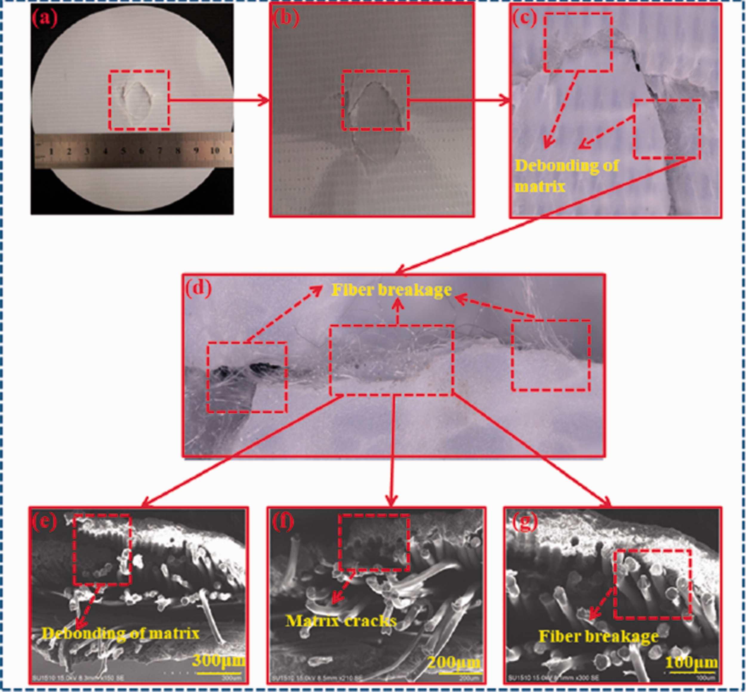
The damage images of composite 1# with flat-nosed punch are shown in Figure 9(a) and (b). It can be seen that shape of the damaged area is semicircular and extends along 90area is semicircularrent types of squeezes the matrix and the fiber under the function of impact load. As the impact displacement increases, the flat-nosed punch drives the flexible composite to move. The fibers in the flexible composite are continuously deformed under impact-tension load. Due to the impact-shearing effect of the flat-nosed punch edge, the surface breakage of the flexible composite is relatively neat. It seems to be “cut” from the flexible composite. The matrix are sheared and broken, fibers are also broken under shearing stress by flat-nosed punch. The damage images of composite 1# with hemispherical-nosed punch are shown in Figure 10(a) and (b). An extension impact failure surface occurred under the impact of the hemispherical-nosed punch. It can be seen that a relatively elliptical damage area is formed. The impact damage is mainly concentrated on the area contact with the punch, which extends along the 90° direction to form a crack. The matrix and fibers are broken under impact-tension load. The damage images of composite 1# with conical-nosed punch are shown in Figure 11(a) and (b). It can be concluded that the damage extends along 0° and 90° direction of inserted yarns and forms cross-shaped failure mode. The matrix was first destroyed by concentrated force under the function of conical-nosed punch. At this time, the flexible composite not completely penetrated by the conical-nosed punch. The fibers near the conical-nosed punch continuously bear the load under friction and tensile force. The failure of the flexible composite material is the stress concentration damage under the action of the conical-nosed punch.
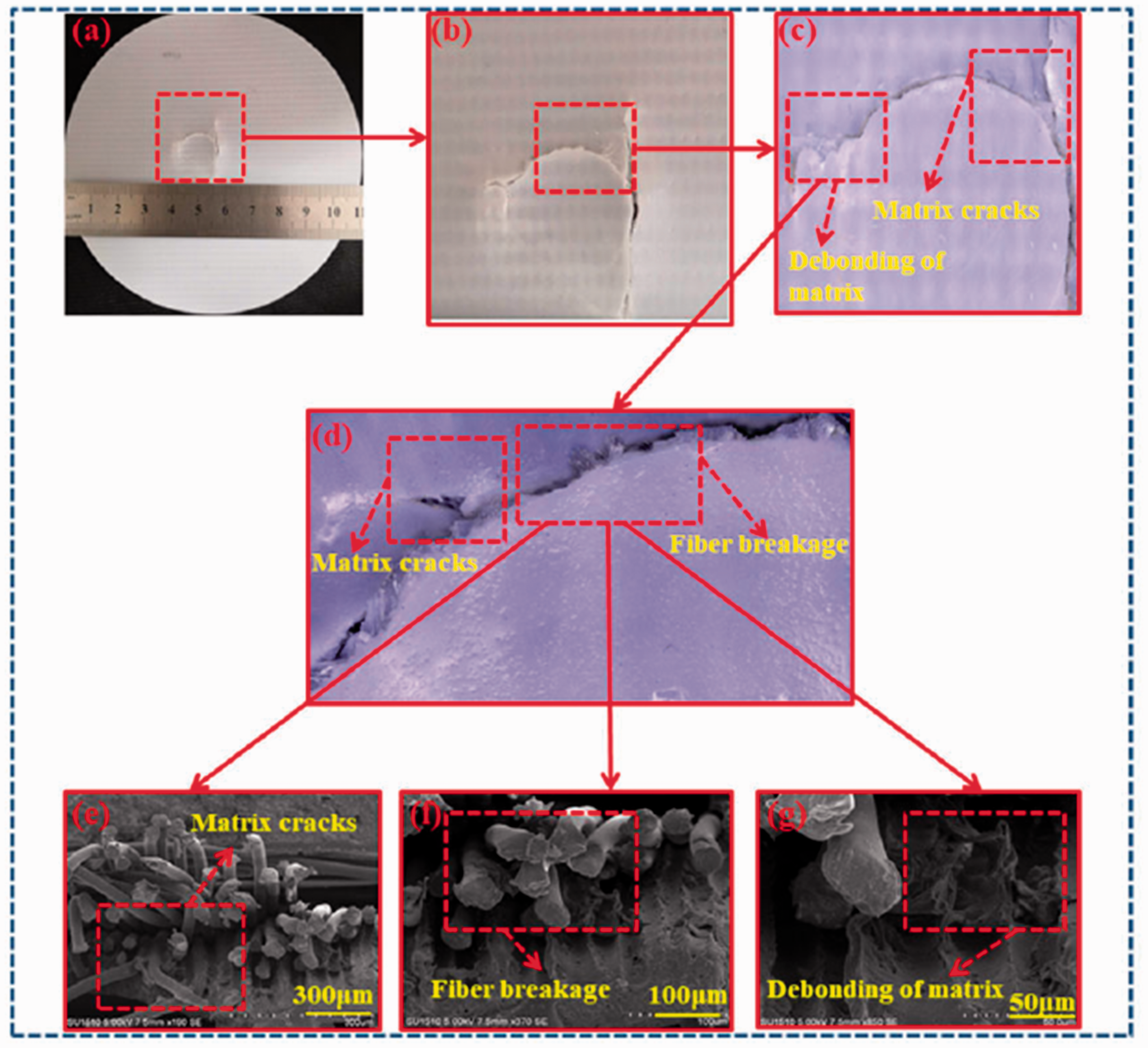
(a, b) The damage morphology of composite 1# with flat-nosed punch; (c, d) ultra-depth three-dimensional (3D) microscopy of composite 1# after impact; (e–g) SEM images of composite 1# after impact.
(a, b) The damage morphology of composite 1# with hemispherical-nosed punch; (c, d) ultra-depth three-dimensional (3D) microscopy of composite 1# after impact; (e–g) SEM images of composite 1# after impact.

(a, b) The damage morphology of composite 1# with conical-nosed punch; (c, d) ultra-depth three-dimensional (3D) microscopy of composite 1# after impact; (e–g) SEM images of composite 1# after impact.
Low-velocity impact of flexible composite materials is a relatively complicated mode of multiple forces coupling failure. In the low-velocity impact test, the composite sample appears to be subjected to compressive stress on the upper side and tensile stress on the bottom side, including in-plane shear stress. Ultra-depth views of composite 1# after impact are shown in Figure 9(c) and (d), Figure 10(c) and (d) and Figure 11(c) and (d). It is observed that matrix cracks, fiber breakage, interfacial debonding of the matrix and fibers are the main failure modes of the biaxial warp-knitted flexible composite [26]. In the first stage, fibers and matrix began to appear small cracks from the pores under impact load. Then, the transfer of force occurs inside the flexible composite, which is manifested as the deviation and expansion of cracks. When the impact load on the biaxial warp-knitted flexible composite reaches the maximum, the internal cracks in the flexible composite material continue to increase and the fibers cannot resist the load stress. The matrix is transformed from micro-cracks into whole fractures. A mass of fiber bundles break, and debonding phenomenon occurs between the fiber and the matrix. Crack propagation leads to the ultimate failure of the material along the yarn direction.
Figure 9(e) to (g), Figure 10(e) to (g) and Figure 11(e) to (g) shows SEM image of composite 1# after low-velocity impact. It can be concluded the cross-section of the biaxial warp knitted flexible composite material shows obvious interfacial debonding phenomenon between matrix and the fiber. There may be original holes and gaps in the biaxial warp-knitted flexible composite. The weak links are subject to crack propagation or migration under the action of external force. The impact stress exceeds the strength of the flexible composite material, resulting in the failure of the composite. And the fibers in the cross section of the biaxial warp-knitted flexible composite material are extracted. After the impact load is applied, the matrix gradually transfers the stress to the high-strength polyester fibers, which causes the fibers to be pulled out of the matrix. The stress is concentrated in the weak area of the composite under the impact load. Finally, the fracture occurs along the contact surface of the yarn.
Conclusion
This paper investigated the effect of the initial impact energy, high tenacity polyester linear density, inserted yarns density and impactor shapes with warp-knitted flexible composites subject to low-velocity impact. The following conclusions can be reached: The energy absorption could be divided into three stages during impact process. In the first stage, the impact energy is absorbed by deformation of the matrix on the biaxial warp-knitted flexible composite. In the second stage, the matrix of the sample is destroyed and the biaxial warp-knitted fabric is subjected to the impact load. Finally, the impact energy absorption of biaxial warp-knitted flexible composite reaches the ultimate value when both types of deformation reach the limitation. After the composite material failed completely, there exhibits large decreases in the load-time curve. The initial impact energy has minor effect on the energy absorption performance of the flexible composite under low-velocity impact. The matrix and the reinforcement were completely destroyed because of thin thickness of the biaxial warp-knitted flexible composite. Even if the impact energy is increased, the energy absorption of the sample cannot continue to increase. With the high tenacity polyester linear density and inserted yarns density increases, the impact resistance capability increases. These performances are expressed in higher load, higher energy absorption and higher damage time. The increase of linear density and inserted yarns density promote the impact load bearing capacity of the flexible composite material per unit area. Under the action of the flat-nosed punch, the failures of the biaxial warp-knitted flexible composite are mainly impact-compression and impact-shear failure. The failure shape of the sample is semicircular, and the crack extends along the 90° direction. The failure of the biaxial warp-knitted flexible composite is mainly impact-tension failure with hemispherical-nosed punch. It can be seen that a relatively elliptical damage area is formed. The biaxial warp-knitted flexible composite is destroyed by concentrated force under the function of conical-nosed punch. The damage extends along 0° and 90° direction of inserted yarns and forms cross-shaped failure mode. The matrix cracks, fiber breakage and interfacial debonding between matrix and the fiber bundles are the main failure modes of the biaxial warp-knitted flexible composite. Although this study could provide basic reference to structural design of the lattice structure inflatable membrane material, some limitations still exist. The mathematically modeled of impact response are not proposed. These characteristics will be taken into account in further developments of this investigate.
Footnotes
Declaration of conflicting interests
The author(s) declared no potential conflicts of interest with respect to the research, authorship, and/or publication of this article.
Funding
The author(s) disclosed receipt of the following financial support for the research, authorship, and/or publication of this article: The authors acknowledge the financial support from the National Science Funds of China (11972172), the Fundamental Research Funds for the Central Universities (JUSRP22026, JUSRP52013B), and a Project Funded by the Priority Academic Program Development of Jiangsu Higher Education Institutions (PAP).