
Abstract
This work compares the low velocity impact (LVI) behavior of conventional fiber metal laminate (FML) with hybrid fiber metal laminates (H-FML) that include an elastomer layer. The aim is to demonstrate the potential of the proposed composite comprising metal, elastomer, and carbon-fiber-reinforced polymer (CFRP) to meet the high demands of emerging products that require lightweight materials. Experimental methodologies and finite element (FE) analysis are used to assess the impact behavior of FML and H-FML. The study evaluates various internal damage processes and the distribution of energy of each ingredient and interaction during the LVI to understand the behavior of the laminates. The results show that the inclusion of elastomer leads to a wider energy distribution and greater participation of the proposed H-FML composites in bearing the load rather than focusing only on the impact area. The materials are used more efficiently in energy absorption since a more extensive energy distribution inside the hybrid laminate takes place. The amount and proportion of energy absorption by each component in laminates are influenced by introduction of the elastomer. The study highlights the potential of using innovative hybrid laminates for energy absorption, and the placement of the elastomer in the laminates affects the extent of energy absorption by each component.
Keywords
Introduction
FMLs, which are made up of layers of fiber-reinforced polymer and metals, are used in a variety of aircraft components today.1,2 They have excellent mechanical characteristics and fatigue behaviour. 3 GLARE is the short name for the most frequent mix of glass fibre reinforced polymers and aluminium sheets (glass laminate aluminium reinforced epoxy). Low velocity impact study on FMLs with different layup configurations were studied 4 and it was found that maximum impact force corresponded to FMLs that were composed of Kevlar fabric on impact side and glass fabric on non-impact side. In addition, the highest tensile strength and Young’s modulus among FMLs belonged to FML with Kevlar fabric and glass fabric. Higher specific mechanical characteristics can be attained by replacing glass fibres with carbon fibres. An extensive literature review was carried out on exploring the possibility of incorporating nano particles in development of FMLs. 5 High velocity impact response of carbon fiber reinforced aluminium laminate (CARALL) toughened by nano silica and zirconia was studied and it was found that controlled addition of nano silica and zirconia resulted in enhanced performance of CARALL against high velocity impact. 6 Similarly, effect on addition of micro glass powder into basalt fiber reinforced epoxy composites on the charpy impact behaviour was investigated and was found that adding micro glass powder increased energy absorption. 7 The combination of aluminium sheets with carbon fibres, on the other hand, frequently results in galvanic corrosion at the contact. 8 Furthermore, the large difference in thermal expansion coefficients between these materials results in considerable residual strains following the curing process in a hot mould. 9 By adding layers of glass fibres, different techniques to isolating the aluminium from the carbon-fiber-reinforced polymer (CFRP) layers have been examined. 10 Another option is to use an elastomeric interlayer to separate the metal sheets. Furthermore, galvanic corrosion can be avoided, 11 as well as the damping behaviour12,13 and impact performance can be altered.14–18
Typical CFRP hybrid laminates exhibit some disadvantages such as restricted ability to deform, enhanced peak reaction force and behaviour of force deflection being brittle. 19 As a result, in order to meet the high standards for crashworthiness in current automobiles, new approaches must be used. Delamination has also been identified as a prevalent mechanism leading to failure in FML. 20 Interlaminar toughening is a good way to improve the resistance against impact. The composite layup includes multilayers such as films made of thermoplastic, elastomers, and metals. H-FMLs contains variety of constituents such as unidirectional (UD) CFRP, elastomer, and metal layers.12,21 Elastomer materials have been employed in shock absorbent sheets, dampers, and other technical applications.22–25
Making use of elastomer components in composites is an innovative technique to enhance the impact behaviour and mitigate the failure. Experiments by Sarlin et al. 26 studied the impact behaviour of hybrid composite laminate fabricated using elastomer, GFRRP and steel as the constituents as a function of impact energy and rubber thickness. With the inclusion of rubber layers, lasting damage was shown to be significantly reduced. The capacity of the rubber to lessen persistent inelastic deformation was good, according to Mohotti et al. 27 Khodadadi et al. 28 probed the energy absorption of FML plates and discovered that the sheet with elastomers on its striking end helps to absorb more energy. It was found by Taherzadeh-Fard et al. 29 that for ballistic applications, incorporating the elastomer proves beneficial compared to enhancing the thickness of the composite. Ballistic limit velocity of hybrid laminates subjected to high-velocity impacts increases considerably with the introduction of elastomer, according to Arzani et al. 30 The impact of elastomer inclusion on the ballistic impact behaviour of bulletproof panels made of bilayer steel fibre - reinforced masonry was investigated by Maho et al. 31 Rubber insertion has been discovered to work as a confining layer, preventing bullet ricochet.
The use of an elastomer layer in a component subjected to low velocity impact can be beneficial for several reasons. 2 Firstly, elastomers have high deformability and can absorb large amounts of energy during impact. This means that when an elastomer layer is incorporated into a composite material, it can effectively dissipate energy and reduce the risk of damage to the underlying layers. Secondly, the introduction of an elastomer layer can also help to mitigate delamination in composite materials. 32 Delamination is a common failure mode in composites subjected to low velocity impact, where the layers of the material separate from each other. By including an elastomer layer between the layers of the composite, the elastomer can act as a shock absorber and prevent the propagation of delamination. Lastly, elastomers are also highly flexible and can conform to the shape of the impact, thereby distributing the energy of the impact over a larger area. This reduces the stress concentration at any one point and lowers the risk of damage. Overall, the use of elastomer layers in composite materials subjected to low velocity impact can improve the energy absorption, prevent delamination, and reduce the risk of damage. 33
The presence of interlayers can have a significant impact on the bending stiffness of a material. In composite materials, interlayers are often used to bond two or more layers of different materials together. These interlayers can act as a barrier between the layers, decoupling their movements and thereby altering the mechanical properties of the composite. In particular, interlayers can reduce the bending stiffness of a material by increasing its flexibility. This occurs because the interlayer prevents the layers from moving in unison, leading to a reduction in the effective modulus of the composite. Additionally, the presence of an interlayer can introduce stress concentrations at the interface between the layers, which can lead to failure or delamination of the composite under stress. Layer-wise analysis of the stresses and deflection of a three-layer beam configuration consisting of two dissimilar orthotropic adherends of different thicknesses that are joined together by a flexible interlayer has been presented by Alfredson et al. 34 The analysis revealed that configurations where the moduli and thicknesses of the adherends are matched, have the largest potential for compliance increase by reduction of the interlayer shear modulus. Analysis of the three-point flexure loading of a symmetric beam configuration consisting of two identical adherends joined by a flexible layer is presented by Alfredsson et al. 35 where it was proved that a thin, shear deformable layer may effectively decouple the responses of the two beams. Low-velocity impact testing of glass-epoxy composites under different environmental conditions was studied by Doshi et al. 36 Improving damage tolerance of plain weave S-2 glass thick-section composites subjected to high energy impact using interlayers was studied by Samuel et al. 37 Also, an attempt to improve peel strength of glass fiber-epoxy composites with thermoplastic interlayers under different environmental conditions was approached by Doshi et al. 38
The majority of published research concentrates on collisions with a small mass at intermediate or high velocity. However, it is found from the literature that LVI behaviour of elastomeric H-FMLs is minimal. The mechanism of damage responsible in LVI of FMLs differ from that of damage induced due to high velocity impact. 39 Because barely visible impact damage (BVID) is crucial for structural components in operation, our research focuses on LVI loadings. It is crucial to assess the LVI behaviour of H-FMLs and analyse their energy absorption and damage behaviour.
The goal of this study is to investigate the effect of using elastomer in the FML subjected to low velocity impact and evaluate the impact behaviour of H-FML when subjected to LVI loadings to that of regular FML using an experimental method. Internal reasons for mechanical variations are investigated using damage mechanisms such as plastic deformation, delamination, and matrix failure. The role of inclusion of elastomer on the distribution of energy and mechanism leading to damage in proposed FMLs are assessed in the present study. The novelty of the present study lies in development of impact resistant elastomer incorporated fiber metal laminate (FML) which contributes to impact resistant structural applications in aerospace industries.
Materials and methods
Materials
Aluminium
The metallic layer employed is an aerospace grade aluminium alloy 2024 T3 with a thickness of 0.3 mm. Because of its superior plasticity, fracture toughness, and anti-fatigue crack formation, it is preferred for traditional FML.
Elastomer
Natural rubber is used as an elastomer layer in this study, which has a density of 1200 kg/m3 and thickness of 0.5 mm.
Carbon fiber reinforced plastic
Bangalore-based Orion Systems provides the woven carbon fiber fabric. In developing CFRP, amount of matrix (polypropylene) used is 38% by weight and that results in 55% by volume. A single ply has a nominal thickness of 0.15 mm.
Manufacturing of hybrid composite laminates
In a hot mould, the stacked laminates are cured. The curing temperature is 150°C, with a pressure of 23 bar and a duration of 300 s. Since the CFRP is entirely cured after 120 s, the curing time of 480 s is determined by the elastomer.
40
The plate measures 300 mm × 300 mm in size. The configuration of the H-FML plate tested in this work is designated as (a) Schematic representation of H-FML and (b) micrograph of section.
LVI test
LVI testing is performed of the developed FMLs are carried out in accordance with ASTM D7136
27
standard. The specimen is 150 mm × 150 mm × 2.5 mm in dimension. Figure 2 depicts the impactor and fixture. The impactor has a diameter of 18 mm and weighs 8 kg 10 J is the impact energy, respectively. (a) Specimen; (b) Impactor and (c) Fixture used for testing.
Modelling and simulation
The FE simulation is carried out with the help of commercially available FE ABAQUS 6.14/Explicit software. According to the testing circumstances, the suggested composites and projectile are modelled and assessed. The suggested composite is represented as a flexible material, whereas the projectile is treated as a stiff material. As boundary conditions, the displacement in z-direction is constrained in the supporting area of the support window and in the four clamped areas of the four clips. Nine cohesive zones are used to model the interfaces of the configuration namely two interfaces between aluminum and elastomer, two interfaces between elastomer and CFRP, and five interfaces between 0° CFRP and 90° CFRP. The element types of reduced integrated 8-node quadrilateral continuum shell elements (SC8R) and 8-node three-dimensional cohesive elements (COH3D8) are used for intra-laminar and inter-laminar modelling of CFRP. The aluminum and rubber are meshed using reduced integrated 8-node three-dimensional solid elements (C3D8R) and 8-node three-dimensional solid elements (C3D8), respectively. The kinematic contact method is adopted to describe the contact between impactor and plate with the friction coefficient μ = 0.3.
The composite plates are given corresponding material characteristics, and the projectile is given a mass. The dimensions of the laminates and the projectile are kept the same as in the experiment. Each layer of aluminium, elastomer, and CFRP is modelled independently before being combined. The projectile’s reference point is defined, and the velocity is supplied. Both the laminates and the projectile are made of free mesh. Prior to doing the real FE investigation, a mesh convergence study is undertaken on the same principles as Ansari and Chakrabarti,41,42 Husain et al.
43
for impact studies and it was found that a mesh division of 40 × 40 showed good convergence as shown in Figure 3. Thus, the same has been used in the actual FE study. Mesh convergence plot for different mesh division (Vi = 1.58 m/s).
Properties of aluminium.
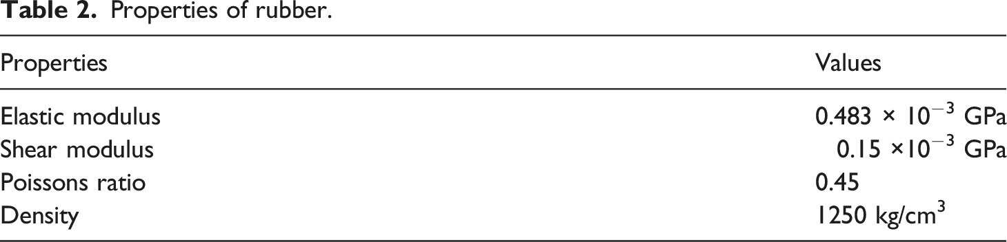
Properties of rubber.
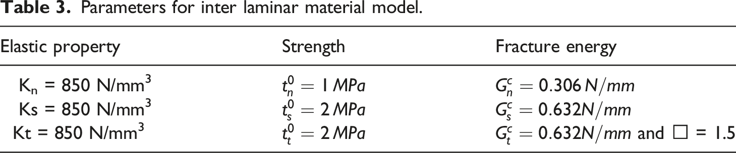
Parameters for inter laminar material model.
Results and discussion
To explain the variations in impact reactions, this section examines the intrinsic damage processes of standard FML and H-FML. In order to understand the reasons for the shift in damage modes with the addition of elastomer, it is also necessary to examine the energy distribution of the parts and interfaces and dissipation of energy due to induction of damage.
Damage mechanism of H-FML compared to FML
Without an elastomeric layer, the FML has a 1.5 mm thickness and is constructed of 0.3 mm aluminium facing sheets and 0.9 mm CFRP cores. FML has a configuration of Force-displacement and Energy-Time curve for FML and H-FML at 10 J.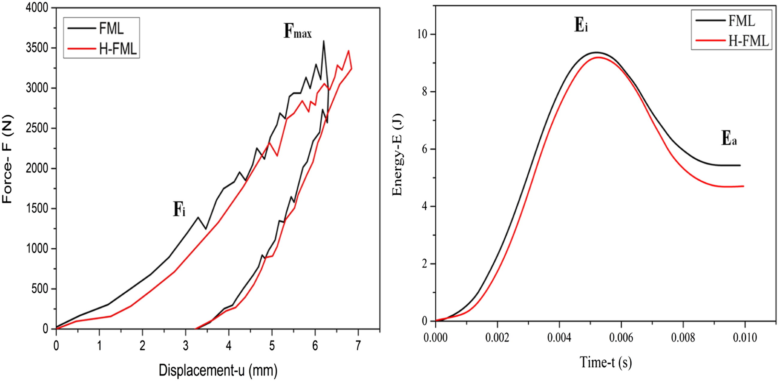
The damage mechanisms in FMLs can be complex and multifaceted, depending on the type and orientation of the fibers and the properties of the metal layers. One common damage mechanism in FMLs is delamination, which occurs when the interfaces between the metal and polymer layers separate. This can be caused by excessive loading, impact, or thermal cycling. When the load is applied to the FMLs, the metal layers tend to stretch and the polymer layers tend to compress due to the differences in their mechanical properties. The metal layers are typically stiffer and stronger than the polymer layers, and are therefore able to withstand higher tensile stresses without deforming or breaking. The polymer layers, on the other hand, are typically more flexible and resilient, and are able to absorb and dissipate energy more effectively. As the FML is subjected to an impact load, the metal layers initially absorb most of the load, while the polymer layers deform and absorb energy through compression and shear. This helps to distribute the load over a larger area and prevent local damage. However, if the load is too high or sustained for too long, the metal layers may eventually yield and fracture, leading to failure of the FML.
If the load exceeds the interfacial strength between the metal and polymer layers, delamination can occur. Delamination can also occur due to improper handling during manufacturing, or exposure to harsh environments. In the context of LVI testing, delamination can be exacerbated by improper handling of the specimens. For example, if the specimens are not carefully prepared and handled, they may be subject to internal stresses or damage that can lead to delamination during testing. To minimize the risk of delamination, it is important to take appropriate precautions during specimen preparation, handling, and testing. This may include using proper cutting tools, minimizing the amount of stress on the specimen during handling, and using appropriate clamping and support during testing.
Delamination at the interface between aluminum and CFRP (carbon fiber reinforced polymer) can occur due to a variety of factors. One common cause is improper adhesion between the two materials. This can happen if the surface of the aluminum is not properly cleaned or roughened before bonding, or if the wrong adhesive is used. Inadequate surface preparation or using improper adhesive can lead to poor bonding strength between the aluminum and the CFRP. Another cause of delamination can be due to excessive loading or impact, which can cause the interface to separate. This can occur if the design of the composite structure does not distribute loads effectively, leading to concentrated stresses at the interface. To prevent or minimize delamination at the interface between aluminum and CFRP, it is important to ensure proper surface preparation and adhesive selection, design the composite structure to distribute loads effectively, and minimize exposure to thermal cycling. Additionally, proper curing and post-curing of the composite structure can also help prevent delamination.
It is common practice in composite manufacturing to prepare the bonding surfaces by cleaning and roughening the substrate surfaces to improve adhesion. The bonding between the metal and composite/elastomer layers is achieved through adhesive bonding. The bonding between the elastomer and metal/composite layers is likely achieved through a combination of mechanical interlocking and chemical bonding. The elastomer layer acts as an adhesive that bonds the metal and composite layers together while also providing flexibility and energy absorption during impact. The specific bonding mechanism between the elastomer and the metal/composite layers may depend on the properties of the elastomer and the surface characteristics of the metal and composite layers.
Carbon fiber reinforced polymer (CFRP) is a composite material that consists of a polymer matrix (typically epoxy) reinforced with carbon fibers. Elastomers, such as rubber, are also commonly used in engineering applications due to their flexibility and ability to absorb energy. When CFRP and elastomers are used in combination, the two materials may interact in such a way that causes damage to the composite structure. In general, the reason for the absence of delamination between CFRP and elastomer interactions is the tackiness of the rubber which binds with the CFRP very well and provided excellent bonding.
The thermoplastic elastomer is melted and then molded onto the CFRP surface. The melted elastomer penetrates the microstructure of the CFRP and then solidifies, creating a mechanical interlocking bond between the two materials. The elastomer layer in a hybrid fiber metal laminate (H-FML) plays an important role in decoupling the multiple layers of the laminate. In a typical FML, the metal layer provides stiffness and strength, while the fiber-reinforced polymer (FRP) layer provides additional strength and stiffness while also contributing to the laminate’s toughness and damage resistance. The elastomer layer is introduced between the metal and FRP layers to act as a compliant layer that can absorb and distribute interfacial stresses and reduce the potential for delamination. The elastomer layer provides a flexible interlayer that allows the metal and FRP layers to move relative to each other without causing interfacial stresses. This decoupling effect helps to reduce the risk of delamination, and also improves the energy absorption and damage tolerance of the H-FML laminate.
The ductility of the interlayer can help to reduce the shear stresses that build up between the metal and fiber-reinforced polymer (FRP) layers in a FML. The interlayer, which is typically made of an elastomeric material, provides a compliant interface between the metal and FRP layers. The ductility of the elastomeric interlayer is important because it allows the interlayer to deform and absorb energy under load, which can help to reduce the peak stresses that occur between the metal and FRP layers. The ductility of the interlayer also helps to ensure that it does not fail catastrophically under load, which can lead to a loss of laminate performance.
Aluminum’s plastic energy dissipation
The basic mechanism for energy absorption is through the plastic deformation of aluminium after yielding. This part of energy increases slowly at first, but increases rapidly at displacements greater than 5 mm, as seen in Figure 5. Once the displacement of the impactor reaches its maximum value, the energy becomes unaltered. This is the phase of rebound. Because of high fracture toughness, the plastic energy displacement curve grows steadily during the loading process with little fluctuation. Aluminium shows no sign of fracture at an impact energy of 10 J. The elastomer in H-FML lowers the amount in the aluminium. Absorption of energy by plastic deformation of aluminium in FML and H-FML (a) F-u curve of HML; (b) F-u curve of H-FML; (c) Plastic energy comparison and (d) Force comparison.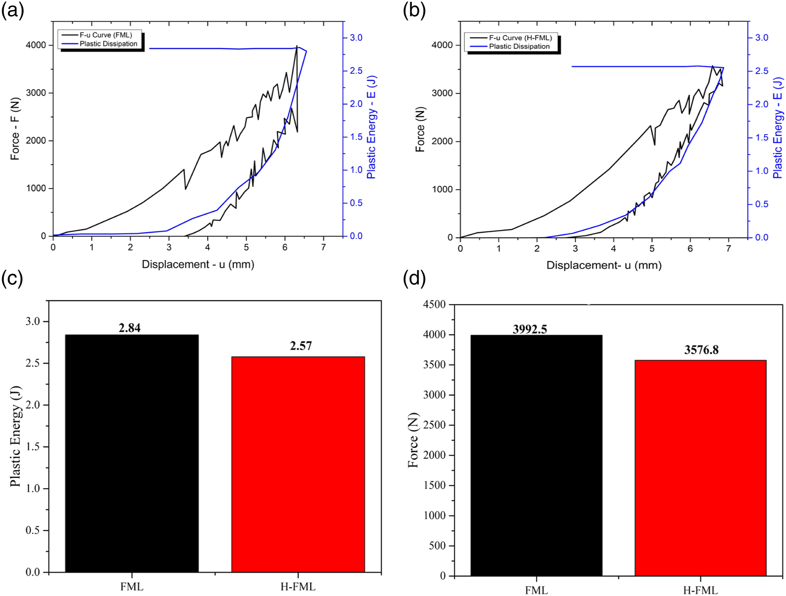
Plastic energy contributes for 28.4% of total absorbed energy in FML and 25.7% in H-FML. Because other forms of damage are minimised, the proportion for H-FML is larger.
Dissipation of energy as a result of delamination
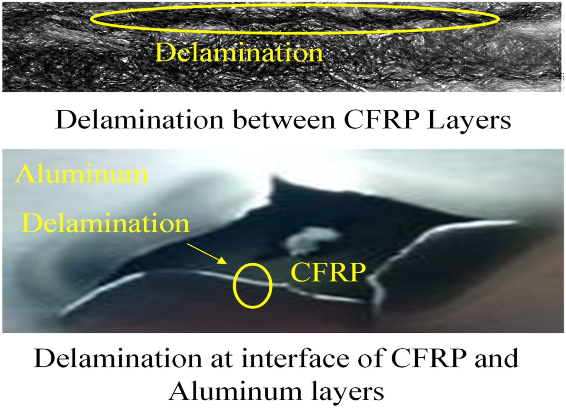
FML’s initial load decrease happens about 1470 N as shown in Figure 5(a). Following the initial matrix break shown in Figure 6, extensive zones of delamination develop between CFRPs of 0° and 90°, as well as at the interface of CFRP and aluminium as shown in Figure 6. For H-FML, the initial load decrease occurs around 2430 N, representing a 65.3% increase over its counterpart FML. Quick drop in the load is caused by the crack energy following the initial matrix break, massive zone delamination at interface of CFRP of 0° and 90°. However, the amount of fracture energy absorbed inside H-FML at interface of CFRP of 0° and 90° is smaller than FML. Finally, the elastomer apart from arresting CFRP-aluminum surface delamination, it also successfully safegaurds the contact at interface of CFRP of 0° and 90° (Figure 7). Crack energy in (a) FML; (b) H-FML (c) their comparison and (d) matrix cracking. Delamination between CFRP layers and interface of CFRP and aluminium.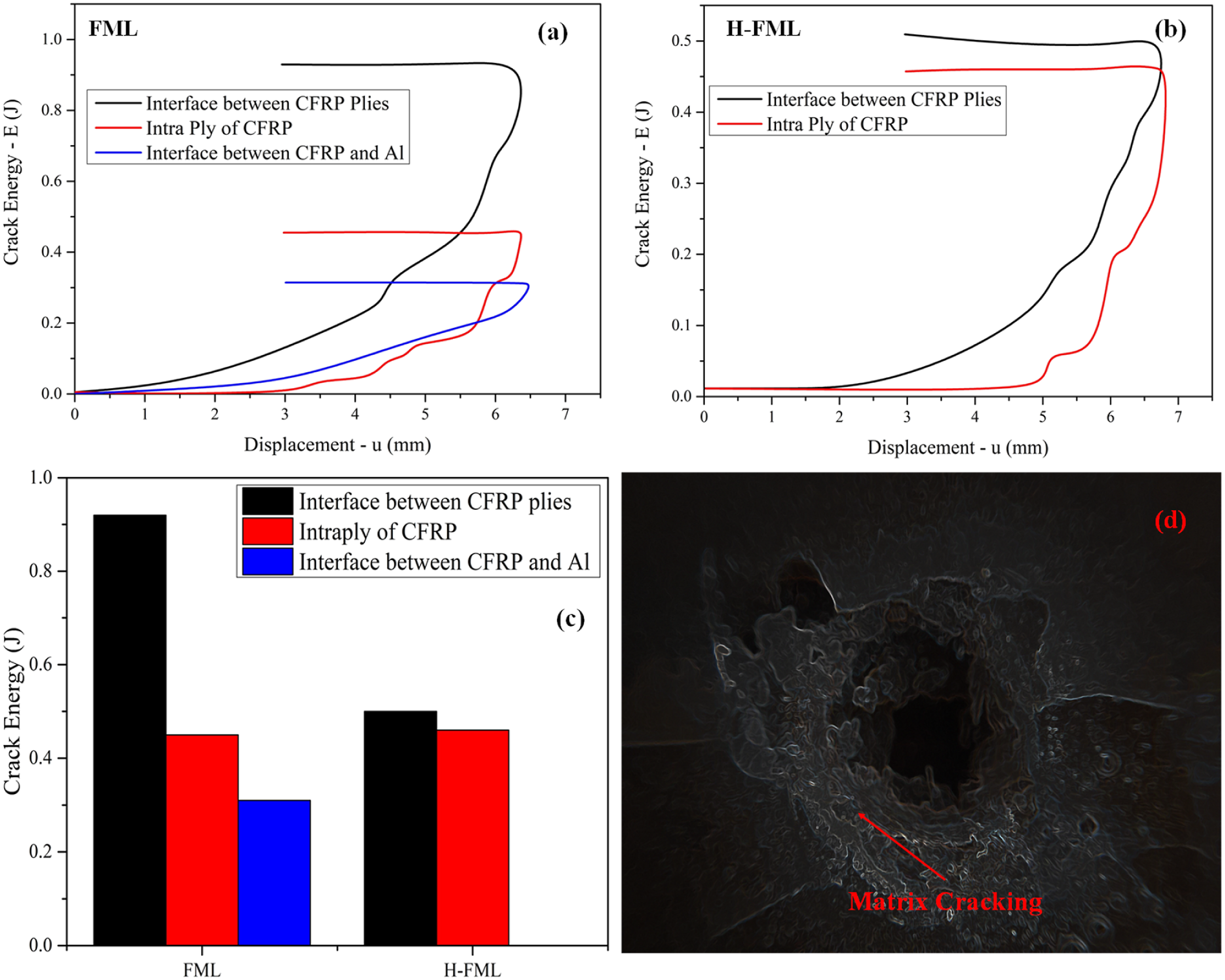
The load increases and oscillates more after the initial load decrease. Another noticeable decrease in load is present. Major cause is yet another breakage of matrix, resulting in delamination at interface of CFRP of 0° and 90°, as well at interface of CFRP and aluminium. Most important energy dissipation mechanism during the early phase of impact is delamination. The geometry of the delamination region is studied to learn more about the properties of this damage mechanism. The delaminated regions are detected using the damage variable.
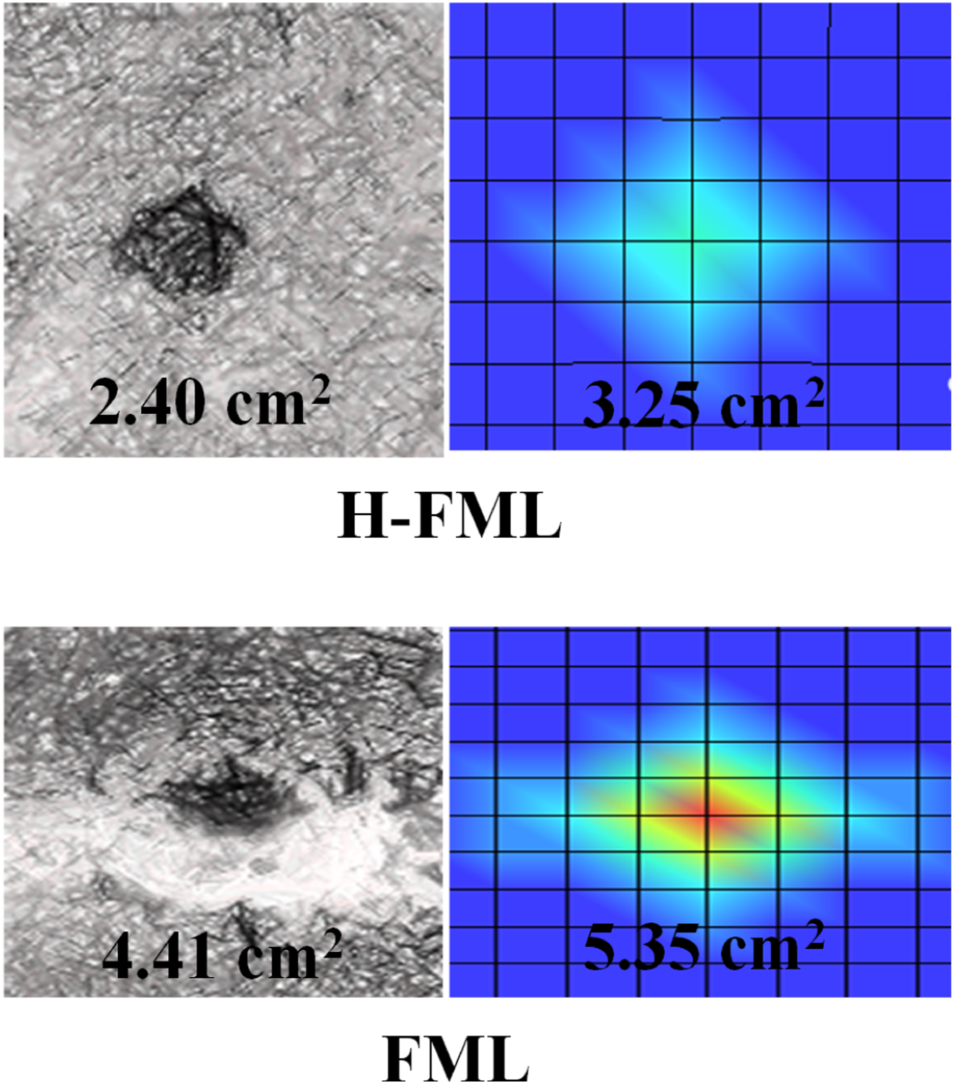
Depending on the stress direction and ply orientation, delamination can spread along or perpendicular to the fibre. The contour of delamination at each contact after impact is depicted in Figure 8. The region along the 0° layer is seriously affected for the contact between aluminium and CFRP ply at 0° in the FML on the side of impact. In a FML that has a layer of Carbon Fiber Reinforced Polymer (CFRP) at 0° orientation in contact with an aluminum layer, the region along the 0° layer is likely to be seriously affected if the FML is impacted on the side of the aluminum layer. The reason for this is that the aluminum layer is relatively soft compared to the CFRP layer, and as a result, the aluminum layer will deform more easily under impact loading. This deformation can cause the interface between the aluminum and CFRP layers to separate, resulting in delamination and significant damage to the 0° layer. When delamination occurs at the juncture of CFRP (0° and 90°), the morphologies of the delaminated regions are equivalent in both laminates. Below the cohesive region, the ruptured area’s long axis follows the direction of the fibres, i.e., the backside of impact. When delamination occurs in a composite material, the ruptured area’s long axis typically follows the direction of the fibers. This is known as in-plane delamination. When the delamination occurs below the cohesive region (the region where the fibers are still bonded together), the delamination will tend to follow the fiber direction, as the fibers are the strongest component in that region. If the delamination occurs above the cohesive region, the delamination will tend to be perpendicular to the fiber direction, as the matrix is the strongest component in that region. To summarise, H-FML has a smaller delaminated area than FML as shown in Figure 9, since the amount of fracture energy absorbed inside H-FML at interface of CFRP of 0° and 90° is smaller than FML. Post impact delamination in fiber metal laminate. Comparison of delaminated area in H-FML and FML.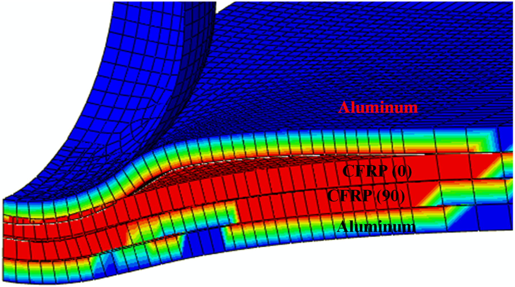
The scalar damage variable Dd is recorded along the x-coordinate of the panel in each interface to quantify the difference in location information, as illustrated in Figure 10. It should be noted that the damaged zone is not spherical, and the image only depicts data along a line from the impact point to the boundary. It was discovered that delamination happens up to a normalised distance of 0.95 for all FML interfaces, but it is 0.6 for H-FML. For H-FML, the value rises again when it approaches the normalised distance of 0.6. Damage variable for delamination along the length of panel for FML and H-FML.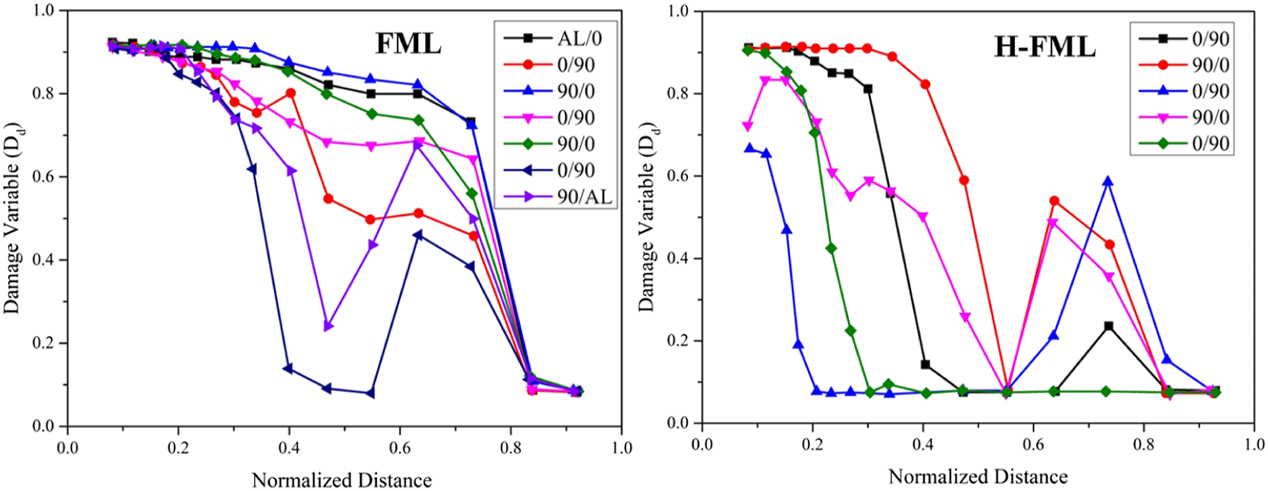
Dissipation of energy as a result of failure of matrix
When a 10 J impact is applied to a CFRP panel, the major intra-ply damage mechanism is matrix failure. Energy absorption due to matrix fracture is virtually same for FML and H-FML, although the ratio changes depending on the ply, as seen in Figure 11(a) and (b). The percentage is larger on the front side of H- FML and lower on the backside. (a) Matrix failure in FML and H-FML following impact and (b) crack damage energy.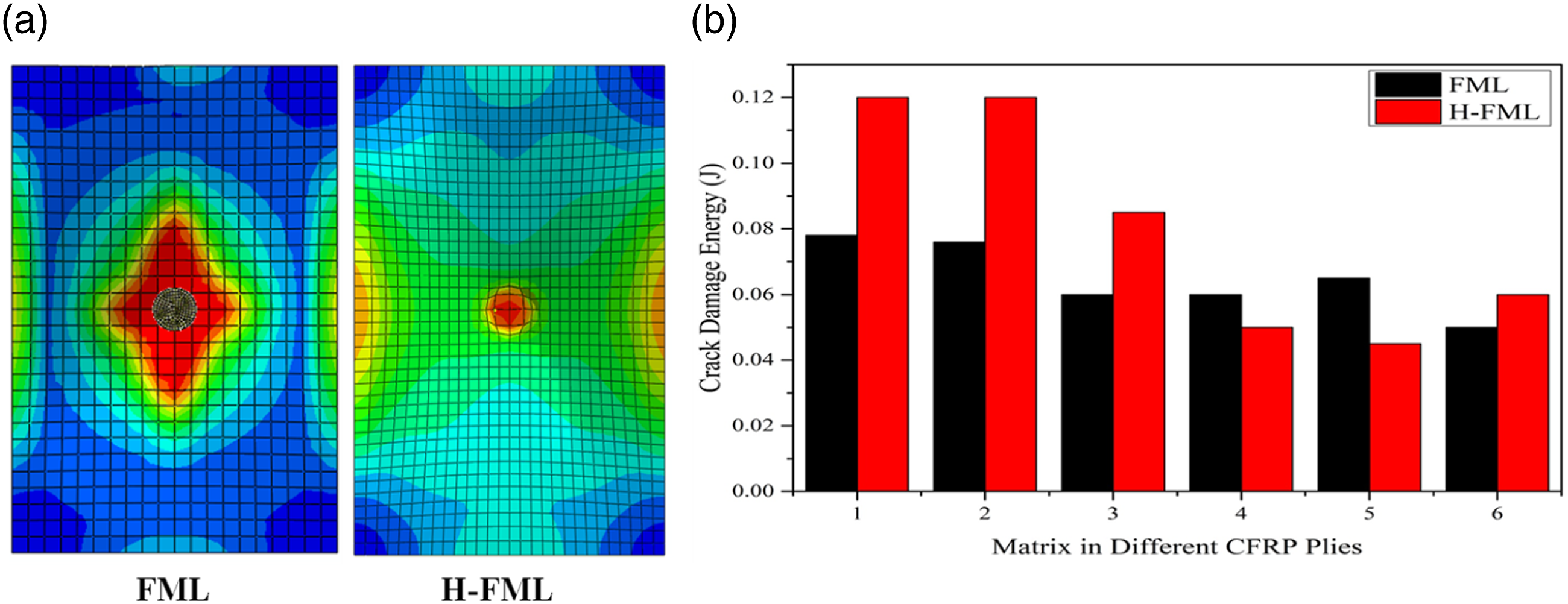
The red result of the matrix tensile initiation criteria implies entire matrix failure, whereas the blue value shows undamaged region. Elastomers are used to focus the damage on the face where impact occurs. The failure of matrix is less intensive in the little region near the impactor and more dispersed over each ply. Delamination below the relevant ply follows a similar pattern to matrix failure. Additionally, this demonstrates that matrix disintegration is to held responsible for the significant delamination damage. This is in line with the concept of a sharp rise in absorption of energy by delamination shortly after the preliminary matrix break, which has been observed (Figure 6). Furthermore, when compared to FML, the start of the matrix break is delayed in H-FML. This is because the stresses in hybrid laminates are spread across a larger surface, resulting in lower absolute values as compared to FML.
Energy distribution of H-FML compared to FML during the impact
The kinetic energy of the impactor is transferred into the composite through damage and other impact-related processes including strain energy and laminate acceleration (both of which are ignored throughout this research). The deterioration to the hybrid composites is directly correlated with the quantity of load-bearing materials used in the construction. Studying the distribution of energy during the impact process is essential for figuring out the fundamental causes of the destructive processes.
Hybrid laminate component’s distribution of energy
The energy distribution within every component for two hybrid composites during impact with 10 J is examined in this section. The distribution of energy for each materials throughout period is seen in Figure 12. We found that the main means by which energy is transferred from the impactor during the impact is through the distribution of energy in aluminium and CFRP. When the elastomer is introduced, the energy held at the peak by the aluminium increases by 7.8%. It explains the decrease in energy wasted by plasticity in H-FML. Comparison of distribution of energy between FML and H-FML.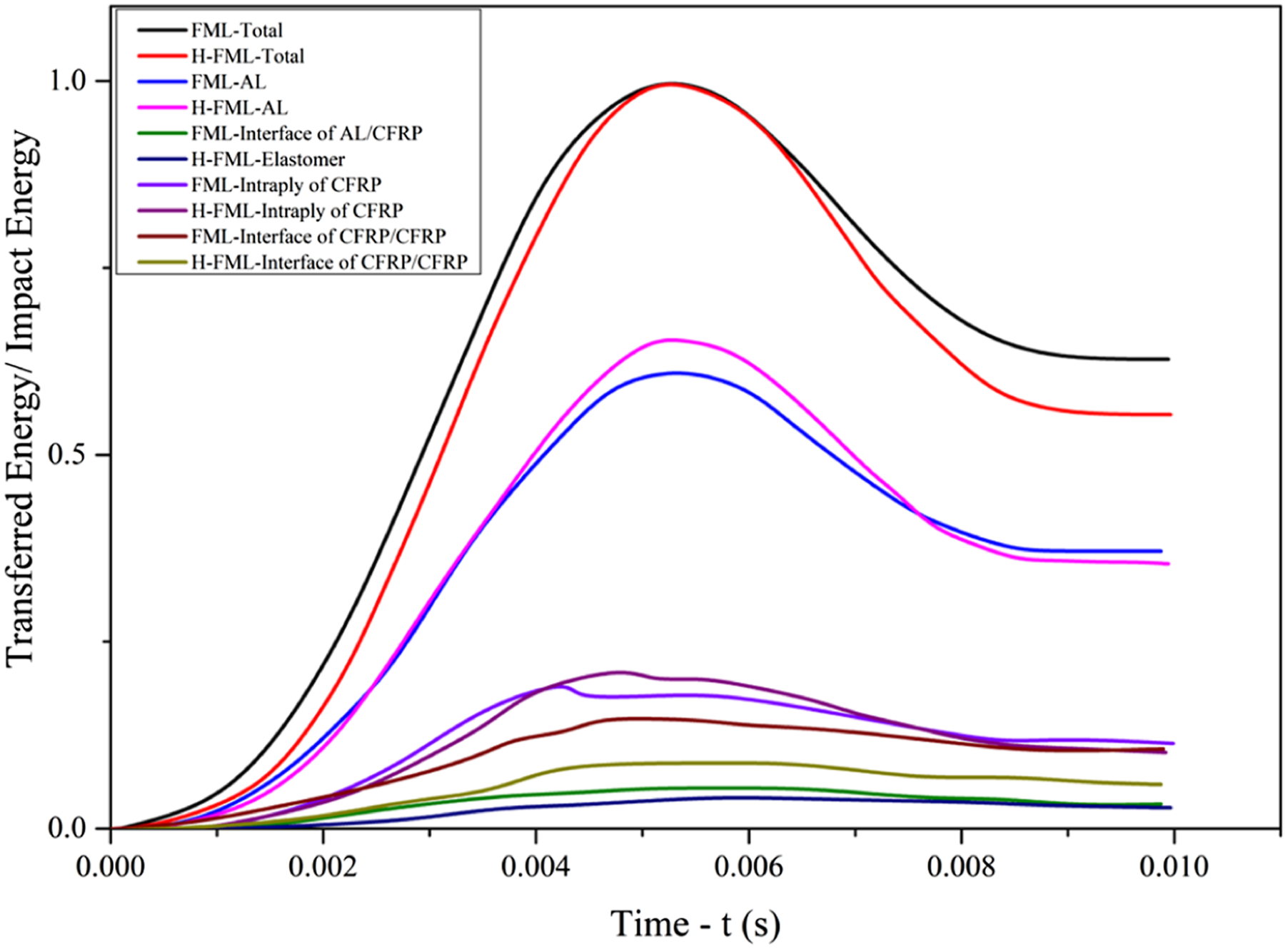
The use of elastomer distributes the weight even farther. More components are involved in elastic deformation, and the metal is secured against localized distortion (plastically). Elastomeric layer incorporated in H-FML absorbs an energy of 17.7% lower than the energy stored by aluminium and CFRP interface. This implies that the elastomer’s major job during an impact event is not storing an additional energy, instead to disperse the localized kinetic energy to the laminate’s global location. Elastomer’s maximum storage of energy is lower than interface of aluminium and CFRP. This, however, has no effect on the H-FML’s total load-bearing capability since the energy is passed to other damage processes. The insertion of an elastomer layer reduces the fraction engaged in load-bearing at the contact between CFRP plies. When compared to FML, the energy ratio retained by the interfaces between the plies of CFRP at the peak in H-FML is lowered by roughly 35%. This shows that by changing the proportion of the material involved in load-bearing, the inclusion of elastomeric layer improves the quality of such interaction of aluminium and CFRP and preserves the contact between CFRP plies at 0° and 90°.
Distribution of deformation
Near field region is referred to the area of the laminate which comes in contact with the impactor during impact event and rest of the area of laminate is referred to as far field region as shown in Figure 13. H-FML undergoes maximum displacement compared to FML in the far filed region considering the bottom layer deformation. Due to the inclusion of elastomeric layer, the deformation is even further. As a result of more material being used, laminate material usage efficiency is increased. The metal layer deforms plastically in response to this movement. Due to the elastomer’s enhancement of the outer layers' membrane effect, the material from the impact zone to the far field may be used for energy absorption quite successfully.
45
Deformation distribution if hybrid FMLs.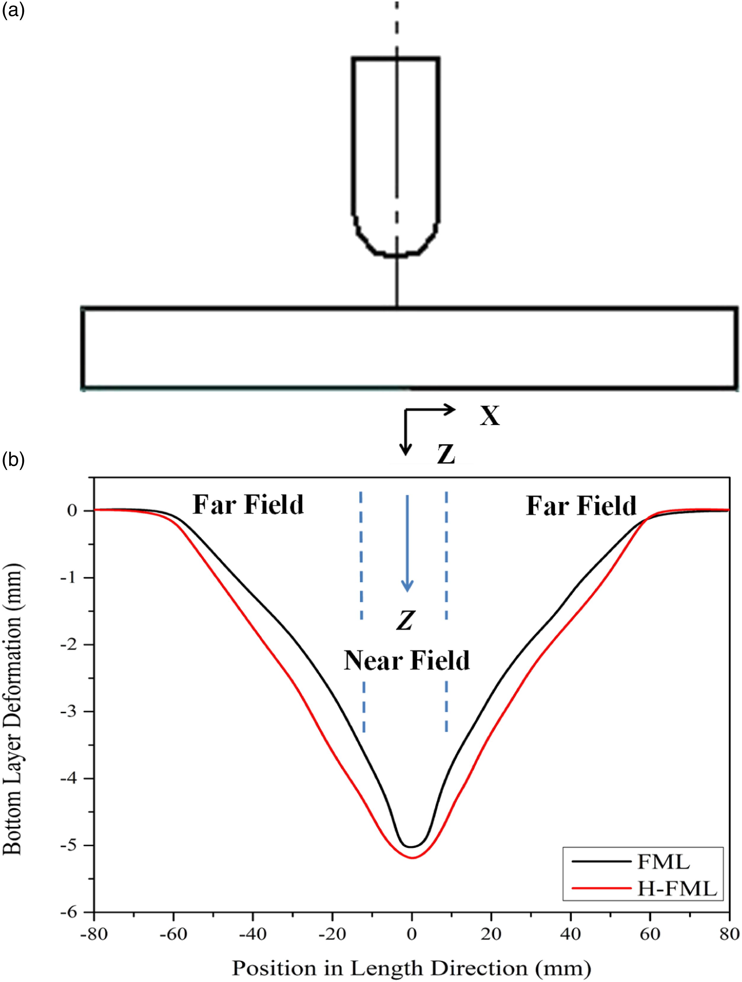
Comparative study
In order to justify the potentiality of the proposed composite for engineering application, a comparative study of the proposed composites with the composites already developed and available in literature15,18 is carried out. The outcome of the results obtained from the literature considered shows that though the flexible bio composites are excellent energy absorbers both against low velocity and ballistic impact loading, they lack the stiffness which makes them unsuitable for use in structural applications. This disadvantage of the flexible composites are overcome in the H-FMLs proposed in the present study since the proposed H-FMLs apart from exhibiting better energy absorption, avoiding delamination also exhibits better stiffness which was not present in case of flexible composites.
Conclusions
This study examines the impact behaviour of hybrid composites made of normal FML and rubber sheets. The distinction is defined in terms of impact damage mechanisms and energy distribution. From the present study following conclusions are drawn upon: • In comparison to conventional FMLs, H-FMLs exhibit higher load required to cause damage, minimal structural rigidity, larger maximal deformations, reduced forces, and minimal absorption of energy. • Rubber layers are used to distribute the impactor’s weight over a greater surface. As a consequence, greater materials engages in elastic energy absorption, and materials usage rate improves with less damage. • Delamination between CFRP and aluminium is minimised, as is delamination between 0° and 90° CFRP. Aluminum plastic deformation is also reduced. The quantity of wasted energy for intra-laminar CFRP damage is identical for FML and H-FML, but the distribution differs. However, in H-FML, the failure dispersion is greater and more uniform. • The failure distribution in FML is much more focused, with significant damage values near to the impactor. In the future, to increase delamination resistance, the elastomeric layers may be sandwiched between CFRP plies. It would be interesting to look at the impact behaviour of H-FML at various impact energies. • The thickness of an elastomeric layer and a laminate may both be altered. More study will be conducted to determine how the stated impact mechanisms affect the mechanical behaviour of a component. The use of elastomers in the creation of hybrid laminates has the potential to provide unique material solutions.
Footnotes
Declaration of conflicting interests
The author(s) declared no potential conflicts of interest with respect to the research, authorship, and/or publication of this article.
Funding
The author(s) disclosed receipt of the following financial support for the research, authorship, and/or publication of this article: The author Vishwas Mahesh would like to acknowledge the support from SERB, Government of India for providing financial support to carryout his work through TARE scheme (TAR/2021/000016).