
Abstract
PAN/PEG/CNT/cotton composite yarn (PPCCY) was fabricated by impregnating PEG2000–10000 into CNT/cotton yarn (CCY) and coating electrospun PAN around its surface. The effects of PEG type on the morphology, structure, electrical resistance and phase change behavior of the produced composite yarns were studied thoroughly by scanning electron microscopy (SEM), Fourier transform infrared spectroscopy (FTIR), differential scanning calorimetry (DSC), thermal gravimetric(TG), electrical resistance tester and infrared thermal images. The experimental results indicated that the resulting compound yarn consisted of conductive yarn within which the spacing between cotton fibers was fulfilled by PEG, rendering phase transition enthalpy from 126–150 Jg−1. The composite yarn exhibited adjustable temperature and thermal storage and electrical conductivity abilities. The composite yarn demonstrated good responsive properties to external electrical and thermal stimuli and had reversible heat conversion and storage, which shows a promise for applications in electrical wearable fabrics.
Introduction
With the development of intelligent flexible and wearable devices, the demand for multi-functional textiles is increasing and a large number of new functional fibers and yarns have emerged [1–3]. These functional textiles could be used in bionic implants [4], heater [5], sensors and actuators [6], electronic display [7], energy storage and release [8]. In terms of energy storage and conversion, the acquisition of clean renewable energy sources and the improvement of storage/conversion efficiency are of particular concern. Solar energy, as one of clean and green heat sources, has been widely studied and utilized [9, 10]. However, the application of solar energy may be limited by the space and time to some extent. With the development of carbon nanostructured materials, such as carbon nanotubes yarns and graphene fibers [11–13], electrical heat promises to be a good choice of clean green heat sources for smart textiles, allowing precise control of heat supply without time and space limitation.
With a good heat source, effective thermophysical storage compound will be critical in realizing a sustainable energy system. Phase change materials (PCMs) may be a good candidate, which can store and release thermal energy in the form of latent heat during phase transition cycles [8, 14]. PCMs could be either organic (e.g. paraffin, fatty acids and polyethylene glycol, etc.), inorganic (e.g. salt hydrates, etc.) or eutectic mixtures. The PCMs have been widely utilized in thermal energy storage systems, such as indoor thermal management system [15], portable thermal batteries [16, 17], smart thermal microgrids [18, 19], thermal regulating textiles and so on [20, 21]. Polyethylene glycol (PEG), as one of organic solid-liquid phase change materials, is one of the most extensively utilized latent heat storage materials due to its high latent enthalpy, non-toxic and non-corrosive natures [22–24]. Nevertheless, there are some limitations such as low thermal conductivity and leakage of molten PEG into the surrounding. Some efforts have been made to overcome these concerns, including the addition of nanoparticles to improve thermal conductivity and the fabrication of shape-stabilized phase change material to prevent the leakage of PCM [25, 26].
\The form-stable PCMs technique involves how to bound the PCMs in a supporting matrix (e.g. polymers, porous materials), which can prevent the melted PEG from leaking so the whole system keeps in solid state. Polymer-based shape stabilized PCMs have been developed in several methods, including PCM-encapsulated polymeric fiber [23, 27], co-electrospun [28] or coaxial electrospinning [29] and so on [24, 26], which realized the fabrication of form-stable phase change materials. However, there are also several issues in these fabrication technologies, such as the low content of PCMs and the difficulty of large-scale production. In addition, considering heat storage and conversion electronically, multi functions response and coordination mechanism in complex environment are also challenging.
In this work, PAN/PEG/CNT/cotton compound yarn (PPCCY) were fabricated by impregnating PEG into CNT/cotton yarn (CCY) and finished by a coating of electrospun PAN. The resulting compound yarn consisted of conductive yarn within which the spacing between cotton fibers was fulfilled by PEG. The composite yarn exhibited adjustable temperature and thermal storage and electrical conductivity abilities. The compound yarn demonstrated good responsive properties to external electrical and thermal stimuli and had reversible heat conversion and storage, which shows a promise for applications in functional energy storage material.
Experimental
Material and chemical
CNT/cotton yarn (CCY)(156tex) was made according to a well-established method [30](0.025 wt% CNT concentration). Polyacrylonitrile (PAN) chip (Mw = 50,000) was supplied by Shanghai Plastics Co. ltd. (Shanghai, China). Polyethylene glycol (PEG with average molecular weight 2000, 4000, 6000, 10,000), N, N-dimethylformamide (DMF) was analytical reagent and bought from Shanghai Chemical Reagent Co. Inc., China.
Method
Firstly, CNT/cotton yarn (CCY)(made according to a well-established method [30]) was immersed in a melting PEG solution for 30 min and then taken out as core yarn (PCCY). Solution of polyacrylonitrile (PAN) in DMF with concentration 12 wt% was prepared. PAN was electrospun onto the PCCY to get PAN/PEG/CCY compound yarn (PPCCY) using a two-nozzle electrospinning machine, as reported in previous work [31]. As described in Scheme 1, this electrospinning system consists of two nozzles with different charges placed in front of each other, and a rotary grounded metal plate for winding the yarn coated with nano fibers. PAN solution was transferred into the two syringe pumps for electrospinning as shown in Scheme 1. The syringe with positive charge was pumped at 0.5 mL per hour, and the other one with negative charge at 0.3 mL per hour. The applied high voltage power was 15kv. The PCCY was used to collect the electrospun PAN fibers released from both syringe nozzles through the rotating metal plate at a distance of 15 cm. The electrospun fibers carrying opposite charges got attracted towards each other and final discharging resulted in the accumulation of charge-less PAN nanofibers on the surface of PCCY yarn. The obtained yarn was about 1300tex and contained about 40 wt% PEG and 20 wt% PAN. This process can be continuous thus a large-scale production can be achieved.
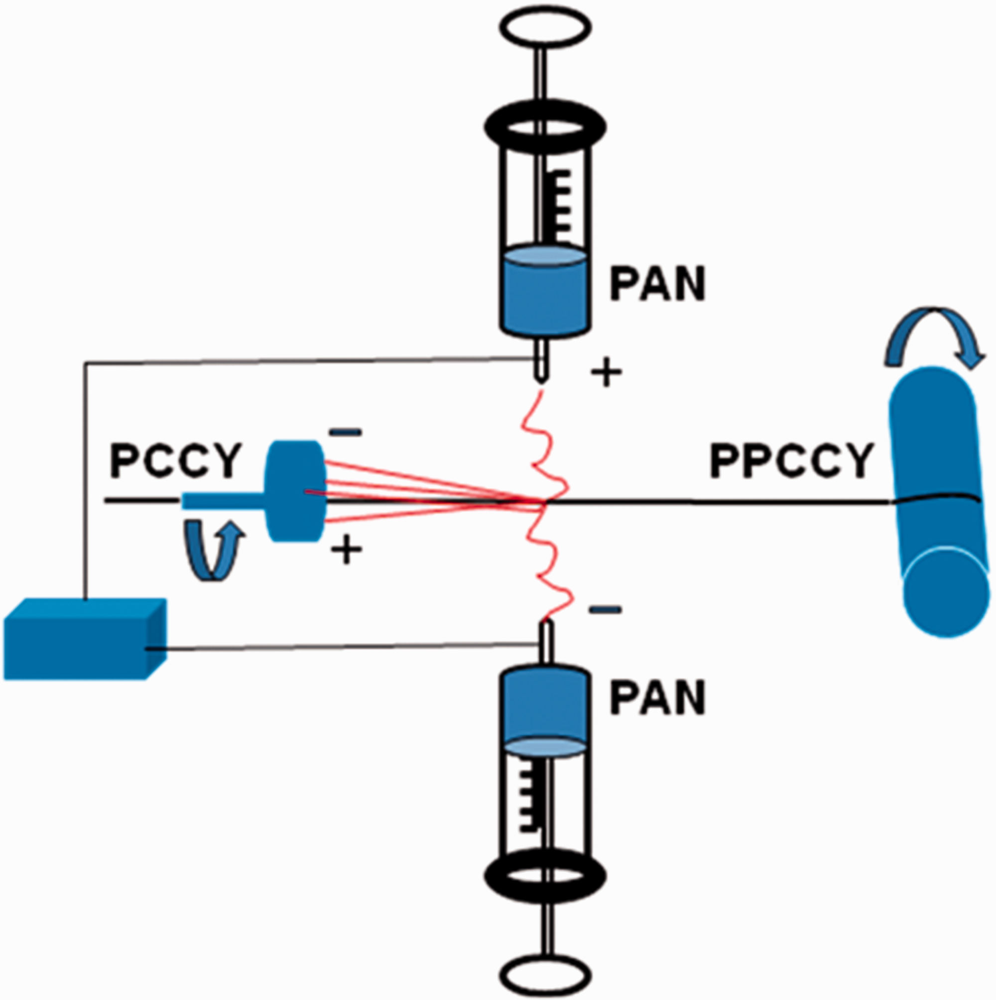
Coating electrospun PAN on PEG/CNT/cotton yarn (PCCY).
Characterization
Scanning electron microscope (SEM, JSM-7800, Japan) was applied to observe the hierarchical structure of the composite yarn with an accelerated voltage of 20 kV.
FTIR spectra were collected using FT-IR VERTEX 70 (Bruker, German) from wavenumber 400 to 4000 cm−1 with a resolution of 4 cm−1 within 32 scans.
The enthalpy changes and transition temperatures of the composite yarn were examined by differential scanning calorimetry (DSC, NETZSCH DSC 204F1). DSC testing was carried out from 10°C to 70°C at a heating and cooling rate of 10 °C/min in nitrogen atmosphere with 50 mL/min flowing rate.
Infrared thermal camera (FLIR ONE Pro) was used to record the temperature change and thermal image of the composite yarn.
The electrical resistance of the composite yarn was tested on a digital multi-meter (Keysight Truevolt 34465 A), attaching two electrodes on the yarn with 1 cm distance.
The thermal decomposition analysis was carried out using a thermal gravimetric analyzer instrument (TG, NETZSCH 209 F1, German) from ambient temperature to 800°C with a heating rate of 10°C/min. The flowing rate of protective nitrogen was 50 mL/min.
Results and discussions
SEM observation
As shown in Figure 1, SEM image of CCY (a) shows that the cotton fibers stack loosely and twist in parallel, aligned with the yarn’s long axis. After PEG impregnation, the pores between cotton fibers were fully filled with PEG, and the fibers were adhered together. After PAN was electrospun onto the PCCY, a micro-nanofibrous web was covered evenly around the PCCY, and a dense skin protective layer was formed. The cross-section images have revealed the core-sheath structure of the composite yarns. The PEG as the phase change material was trapped inside the core with PAN nanofibrous sheath protecting it from leaking.

SEM images showing the morphology of cross section of various yarns: (a) CCY in longitudinal view, (b) cross section of CCY, (c) CCY with electrospun PAN in longitudinal view, (d) cross section of CCY with PAN, (e) to (h) cross section of PPCCY with PEG 2000, PEG 4000, PEG 6000, PEG 10,000 respectively.
FTIR analysis
Figure 2 compares the FTIR spectra of CCY, PCCY and PPCCY yarn. The IR absorption wide peak of the –OH group of cellulose (CCY) was detected at 3343 cm−1, and wide –OH peak of PCCY was observed at 3321 cm–1, the shift is due to the overlapping of pure PEG6000’s –OH group. –OH characteristic peak of PPCCY is centered at 3336 cm–1. The peaks in the regions of 2900–2980, 1430–1470, 1320–1330 and 1220–1230 cm–1 are related to different vibrational modes of C-H in CH and CH2 groups in cellulose, PEG and PAN respectively [32]. The minor peak at 2886 cm–1 in PCCY also belongs to asymmetric bending vibration of –CH2 of PEG. In addition, the characteristic peak of PEG at 1156 cm−1 in PCCY is ascribed to C—O bond stretching vibration. A weak characteristic absorption peak attributed to –C≡N bond (cyanogroups) stretching vibration was detected at 2247 cm−1 in PPCCY sample [33]. The bands centered at 1034 cm−1 in all samples correspond with the skeletal vibration of C-O-C pyranose ring in cellulose [34]. On a whole, IR spectrum results indicates that PAN and PEG structures are reserved in the composite yarn.

FTIR spectrum of various yarns.
DSC analysis
The PPCCY with different PEG type (molecular weight ranging from 2000 to 10,000) was produced and the phase change behavior of the composite yarns was examined using DSC analysis. The DSC curves of PPCCY with different PEG type are shown in Figure 3, and their phase change temperature and latent heat are listed in Table 1. As seen from Figure 3, all composite yarns have clear phase change temperature during heating and cooling process. The latent heat of each yarn during cooling and heating process is close, which indicates the composite yarns can be taken as latent storage materials with reversible transition in the tested temperature range. The DSC curves in Figure 3 show a upshift of the melting temperature with the increase of PEG molecular weight. As shown in Table 1, the corresponding melting temperature was 56.5°C for PEG 2000, 62.6°C for PEG 4000, and 66.3°C for PEG 10,000, and there was no distinct shift compared to pure PEG (shown in Table 2). Certainly there is an obvious reduction of the latent heat ΔH both in heating and cooling process for each PPCCY. The shift to lower enthalpy may be due to the confinement of the cotton fiber network that reduced the PEG crystallization [35]. However, they still possess the high latent heat. The phase change enthalpy of PPCCY during cooling and heating cycle reaches value of 135.3 and 128.8 J/g for PEG 2000, 136.0 and 128.4 J/g for PEG 4000, 150.8 and 150.9 J/g for PEG 6000, 126.0 and 125.3 J/g for PEG 10,000. The obtained composite yarn with the highest latent heat enthalpy of 150.8 J/g possessed the maximum encapsulation efficiency of 73.8%, which is much higher than that of the commercially available phase change textiles [36]. As the Table 1 shows, the phase change enthalpy of PPCCY with 10,000 is lower than that of other composite yarn, which may be due to the effect of high viscosity of PEG10000 on PEG impregnation and loading.

DSC curves of PPCCY with different PEG: (a) heating process; (b) cooling process.
Phase change temperature and enthalpy of PPCCY with various PEG type.
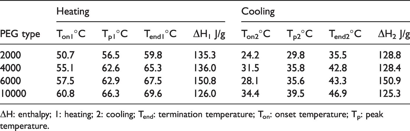
ΔH: enthalpy; 1: heating; 2: cooling; Tend: termination temperature; Ton: onset temperature; Tp: peak temperature.
Phase change temperature and enthalpy of pure PEG.

ΔH: enthalpy; 1: heating; 2: cooling; Tend: termination temperature; Ton: onset temperature; Tp: peak temperature.
The DSC curves recorded for the PPCCY with PEG6000 after five thermal cycles are shown in Figure 4. There are no apparent changes in their shapes after different thermal cycles, and the corresponding transition temperatures and enthalpies are in good agreement with each other, which indicates that the PPCCY has good thermal reliability, reusability, reversibility and stability of heat conversion and storage. The electrospun PAN layer did not hinder the phase change characters of the yarns including the phase transition temperature and enthalpy and thermal stability.

DSC curves of PPCCY with PEG 6000 after five thermal cycles.
Electrical thermal energy conversion and storage
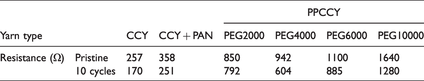
As previous study revealed that the CCY can transfer electrical energy to thermal energy effectively [30], here the effects of PEG on electrical thermal conversion and storage are discussed. Figure 5 describes the electrical thermal energy conversion and storage testing procedure of the composite yarns. For the CCY yarn, the obtained temperature evolution curve exhibits the same characters to that reported in the previous study [31], the surface temperature increases sharply from room temperature to about 110°C within several seconds (Figure 5a) and drops immediately to the room temperature (about 33°C) when the current is off (Figure 5b). Temperature evolution curves of the PPCCY yarns also show similar characters, but their equilibrium temperature is much lower than that of CCY, which is related the resistance. As Table 3 shows, the resistance of PPCCY increases more than two times compared to CCY, while the voltage remains 10 V unchanged, which leads to the decrease of the current and heat value, and the surface temperature decrease of corresponding PPCCY yarns. And with the increase of PEG molecular weight, the resistance of composite yarn increases continuously, thus the equilibrium temperature in the endothermic process decreases correspondingly. In addition, there are also some other differences between CCY and PPCCY. During the temperature rising phase, the curve slope of all PPCCY yarns decreases obviously. And PPCCY samples with PEG 2000 and 4000 undergo a solid-liquid phase transition, while PPCCY sample with PEG 60,000 especially PPCCY with PEG10,000 shows no apparent solid–liquid phase transition. The melting point of PPCCY with PEG10000 onsets at 60°C and its resistance reached 1640 Ω, thus the heat generated by electronic energy under an applied voltage of 10 V is not enough to support the phase transition. When the current is off, the cooling rate of PPCCY is obviously slower than that of CCY. For the composite yarns with PEG4000 and 6000, a temperature platform (after about 25 s) is observed in the range of 41°C–37°C during the exothermic process, which corresponds to the crystallisation of the PEG4000 and 6000. These phenomena confirm that PPCCY composite yarns can absorb and release thermal energy produced from electrical energy.

Temperature evolution curves of various PPCCY through electroheat conversion: (a) endothermic process, (b) exothermic process.
Electrical resistance of various composite yarn.
Taking PPCCY with PEG6000 as an example, the effect of applied voltage on temperature evolution of PPCCY was measured. As Figure 6(a) shows, when the operating voltage increases from 6 to 14 V, the temperature increase presents a steeper trend, and obvious melting platform can be observed when applied voltage reaches 12 V, as Figure 6(c) shows the melting platform under 14 V is from 44°C to 60°C and lasts more than 200 s. Figure 6(b) indicates that the temperature profiles for voltage 10–14 V are relatively consistent. And their platform temperature is close to 42°C during exothermic process, which further confirms electrothermal conversion and phase change functions of PPCCY.

Temperature evolution curves of PPCCY with PEG6000 under different voltage: (a) endothermic process, (b) exothermic process, (c) infrared thermal images of PPCCY with PEG6000 under different time (at 14 V).
Figure 7 presents temperature evolution curves recorded for PPCCY with PEG 6000 under and off an applied voltage of 14 V after 10 cycles. It is clear that the final temperature is elevated during endothermic process, which is due to the resistance reduction after the cycling as Table 3 shows. The elevated and reduced temperature curves are relatively consistent for the 2nd–10th cycles, which demonstrates that PPCCY has stable electrothermal conversion and heat storage-release properties.

Temperature evolution curves of PPCCY with PEG6000 under 14 V repeated for different cycles: (a) endothermic process, (b) exothermic process.
Thermal stability analysis
Figure 8 shows TG-DTG thermogram of various composite yarns. According to the obtained TG curves, weight loss of all samples took place as the temperature increased from room temperature to 800°C at a heating rate of 10°C/min. For all samples, the weight loss took place in one major step, about 60% and 75% for CCY and PPCCY, respectively, representing a process of oxidation and combustion of cellulose and other substances. For CCY sample, a minor weight loss (about 14%) occurred between 370°C–550°C. For all PPCCY samples, a minor weight loss (about 15%) occurred between 280°C–350°C as a result of decomposition reaction of PEG and PAN stabilization reaction [37].The remaining weight of CCY and PPCCY was about 20% and 4%, respectively. DTG profiles show that maximum decomposition rate of CCY is about 11% · min–1 at 340°C, while that of PPCCY is 20% · min–1 at about 390°C. Though the addition of PEG and PAN changed the thermal degradation behavior of the composite yarn, PPCCY and CCY exhibit similar thermal stability on a whole.

The thermograms of various composite yarn (a) thermogravimetric curves, (b) derivative thermogravimetric curves.
Conclusions
In this work, a novel phase change and conductive composite yarn was fabricated using dipping method and two-nozzle electrospinning. In the obtained composite yarn, the CNT/cotton yarn matrix was filled with PEG2000–10000 and coated with electrospun PAN. SEM observation revealed that PEG fulfilled the space between cotton fibers and the CNT/cotton yarn became tact after soaking in the PEG solution. And micro-nanofibrous PAN web was covered evenly around the composite yarn surface forming a protective layer. Though the electrical resistance of CNT/cotton/PEG/PAN yarn increased much after the addition of PEG, it still had good conductivity and can afford heat source for PEG. CNT/cotton/PEG/PAN yarn had adjustable and stable phase transition temperature (56°C–66°C for heating, 35°C–47°C for cooling) and the latent heat ranged from 126 Jg−1. The composite yarn demonstrated its ability to convert electrical energy into heat at appropriate voltage (10–14 V), which can be stored by the composite yarn in the form of latent heat. The storage/release cycles testing of PPCCY with PEG6000 confirmed that the electrothermal conversion and heat storage-release process was stable. The composite yarn can respond to external electrical and thermal stimuli and provide a choice for applications in related electro-to-heat conversion/storage field, though its durability needs to be improved further.
Footnotes
Declaration of conflicting interests
The author(s) declared no potential conflicts of interest with respect to the research, authorship, and/or publication of this article.
Funding
The author(s) disclosed receipt of the following financial support for the research, authorship, and/or publication of this article: The authors are grateful for the support received from National Key R&D Program of China (2017YFB0309100) and Fundamental Research Funds of Wuhan Textile Universities.