
Abstract
Centrifugal electrospinning (CES) was developed by integrating the electrospinning (ES) and centrifugal spinning (CS) concepts to produce oriented and diameter-controlled fibrous scaffolds which were then applied to stimulate the behaviour of fibroblast cells. During the fabrication process, polymer concentrations, rotational speeds, operating voltages, and needle sizes were key parameters to affect the diameters of produced fibres. The mathematical model indicated that the centrifugal force with the power of 2 was the main influence in fabricating thinner fibres, followed by electrostatic force with the power of 1. The developed CES technique could fabricate fibres scaffold ranging from 210 ± 50 nm to 2814 ± 96 nm by only applying low operating voltages and rotation speed which were 10 kV and up to 2000 rpm, respectively. Through optimum parameter, random and aligned nanofibrous were fabricated with the diameter being distributed mainly at 200–400 nm. Aligned nanofibrous demonstrated a high degree of orientation when 88% of the nanofibrous varied at 0°–10°. Compared to random structure, aligned nanofibrous presented high tensile strength, which was approximately 4.35 MPa and appropriate flexibility with 73% of elongation break. Aligned nanofibrous exhibited high cell viabilities with a 2.34 absorbance rate at day 14. The fibroblast cells elongated and accelerated in the orientation of the aligned nanofibrous. Results suggest that fibre aligned scaffolds are possible candidates for wound dressing application.
Keywords
Introduction
Tissue engineering is a relatively new and emerging multidisciplinary field that comprises knowledge of biology and engineering and aims for the development of biological scaffold that is capable of regenerating, maintaining or improving tissue function [1,2]. It usually requires a scaffold with optimized surface properties that will provide cellular inhabitation as well as offer a cell-friendly microenvironment that recaptures the native extracellular matrix (ECM) [1]. Additionally, researchers have acknowledged that the topographical features of ECM can direct cell behaviour [2]. In this regard, processing technologies along with biomaterial composition play an important role in creating high-level biomimetic scaffolds. Among the traditional scaffolds, polymeric fibre-based scaffold in uniform micro/nanoscale fibres, high porosity, and high mechanical strength has a great potential to mimic both morphological and dimensional features of ECM [2–4]. Synthetic polymers such as polypropylene (PP), polycaprolactone (PCL) and polylactic-co-glycolic acid (PLGA) have been broadly utilized as a nanofibrous scaffold. Food and Drug Administration (FDA) have also proven that these materials are suitable for biomedical application due to their good biocompatibility, biodegradable and non-toxic composition [5].
Fibre orientation of random and aligned nanofibrous influence cell behaviour including cells adhesion and growth [6]. An aligned nanofibrous promotes more elongated cell morphology and enhanced cell migration compared to random nanofibrous [4,6,7]. A researcher indicated that dermal fibroblast cells exhibited elongated morphology and accelerated the direction of fibres alignment [6,8], which resulted in an accelerated wound healing process. Aligned nanofibrous could also orient the human ligament fibroblast cells and showed good cell viability as random nanofibrous [4,9,10].
A considerable number of current efforts have focused on fabricated fibres using electrospinning and centrifugal spinning. Both of these techniques have shown efficiency and versatility in fabricating continuous micro/nanoscale fibres. However, the process of electrospinning is limited to large scale production, requires high operating voltage, and is limited to random orientation, which contrasts from native ECM topography and the process becomes more challenging in fabricating aligned fibres. A research team used modified collector such as fast-rotating mandrel electrospinning to form aligned fibres. But the degree of aligned fibres oriented largely depends on the mandrel rotational speed and decrease with the increase in spinning time. Alternatives to collector modification, another technique have been developed using a mechanical system to produce micro/nanoscale fibres. This system is capable of reducing the safety concerns in which researchers utilised a centrifugal force from rotating motor, known as centrifugal spinning (CS) [11–13]. Centrifugal spinning can form micro/nanoscale fibres in aligned oriented at high rotational speed from 5000 to 12000 rpm [14], but the electrospun fibres are formed in non-uniformity and distributed in a ring form between the spinneret and circular collector [15,16].
In recent years, a new method which is a combination of electrospinning and centrifugal spinning, namely, centrifugal electrospinning (CES) has been reported as an efficient technique in fabricating micro/nanoscales fibres. When the external force is applied to the polymer solution, the charged polymer fluid tends to be forced toward the opposite electrode which is a collector. It is expected that this mechanism would control the fluid flow which could lead to high alignment of fabricated fibres. A researcher applied the vertical electrode concept in the CES setup, a rotating spinneret with nozzle and an aluminium collector located under the spinneret. The process used a lower working voltage (2.8–6.0 kV [16], 3 kV [17], and 2–10 kV [13]) and low rotational speed (360–540 rpm [16] and 390 rpm [17]) to form an aligned fibre, but, the resulted fibres suffer from uniformity, wider range fibres up to 4.15 µm and beaded fibres. In addition to that, several works used rotating spinneret with orifices and located at the centre of the hollow cylinder collector. A high operating voltage and rotational speed is required that could prevent the polymer jet dried at orifice exit and the fabricated fibre suspended into the air. The researchers used a high operating voltage ((10–22 kV [18] and 15 kV [19]) and high rotational speed (1440–5040 rpm [13,19]) to form a nanoscale fibre, but the fibre formed were in random oriented. To overcome the drawback, simple setup of CES machine is proposed for enhancing the process of fibre fabrication by applying the concept of the parallel electrode and a nozzle was used to direct the solution out to the collector. It is expected the parallel electrode mechanism will increase the electric field strength between the needle tip and collector during fibre fabrication.
A simple and direct centrifugal electrospinning (CES) setup was proposed in this study to fabricate micro/nanoscale fibres with controlled morphology using an appropriate operating voltage and rotational speed. The mathematical model of the polymeric jet path of CES was discussed to investigate the influence of several operating parameters on the fibre diameter. In the meantime, a series of experimental study was conducted to investigate the influence of the operating parameter to the fibre diameter. An optimum operating parameter of CES was obtained from the mathematical model and experimental study. Subsequently, a continuous random and aligned nanofibrous will be fabricated through the optimum parameters. The physical properties, mechanical properties, and biological characterization of random and aligned nanofibrous were evaluated further compared to a wound dressing scaffold. Additionally, a 3D weave nanofibrous scaffold was fabricated to demonstrate the flexibility of the CES machine. Based on the experimental result, it is expected that the fabricated aligned nanofibrous using developed CES will have potential as a wound dressing scaffold application.
Fabrication and characterization
The concept of fabricating fibres using electrospinning, centrifugal spinning, along with integration of these two techniques was studied in this section. The physical, mechanical, and biological properties of the fabricated fibres were performed to show the potential of the developed machine.
Fabrication system
Electrospinning
Electrospinning was performed using the developed setup for all the samples [5]. The polymer solution was loaded in the syringe and was ejected by a syringe pump to provide a 0.45 mL/h controllable flow rate. A high voltage power supply (Nanon-01A, MECC Co., Ltd., Fukuoka, Japan) with a maximum of 30 kV was applied between the needle and collector plate. Figure 1(a) illustrates the electrospinning process. Briefly, when the solution is fed, there is a drop of polymer solution at the needle tip due to surface tension forces. But, when the operating voltage was applied, the drop of polymer solution developed highly electrically charged and induced charged was evenly distributed over the surface [20,21]. The drop of polymer solution experienced two electrostatic forces, including electrostatic repulsion between the surface charge and a Coulombic force from the applied electric field [20,21]. The electric field force

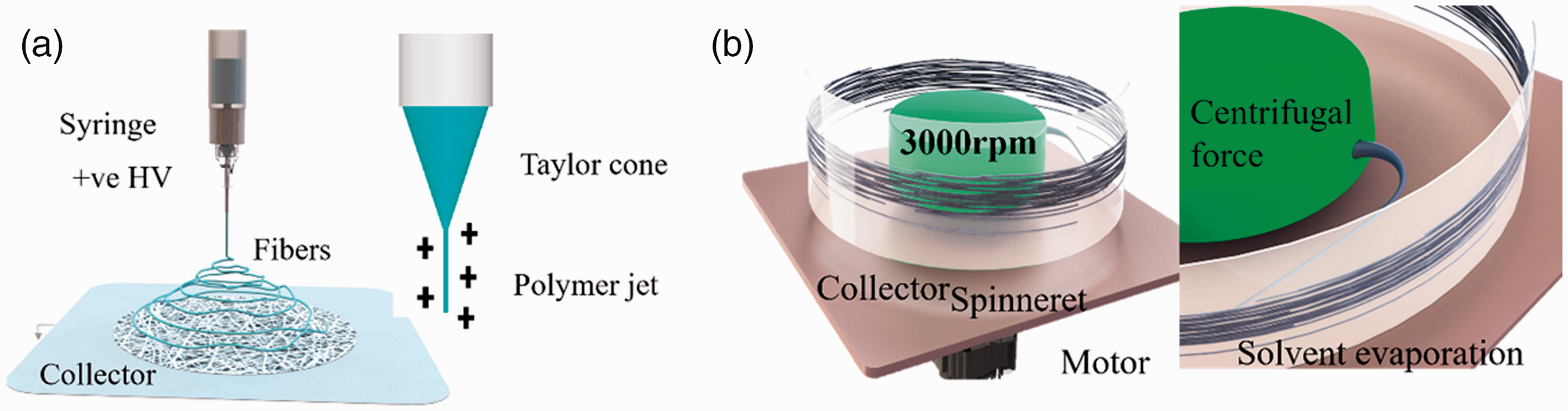
Schematic of (a) electrospinning system (b) centrifugal spinning system.
The electrospinning process began once the electrostatic force overcame the surface tension of the polymer solution. The polymer jet was discharged and continuously stretched, forming thinner fibres.
Centrifugal spinning
A centrifugal system was made of DC brushless motor, BLDC (Troy Motor, Kaohsiung, Taiwan), a spinneret to store the polymer solution and a circular collector. The rotational speed of the BLDC motor used can be varied up to 3500 rpm by a variable resistor. Figure 1(b) shows the schematic of the centrifugal spinning system. To form fibre using CS, three different phases are required to transpire starting from jet initiation to jet extension and finally, fibre formation. In the initial trajectories, polymer jet is determined by the centrifugal force. Due to centrifugal force, the polymer solution sustained by its surface tension is radially transported outward through the needle tip [19]. The centrifugal force acting on the jet is as follow

Centrifugal electrospinning
A direct centrifugal electrospinning system was developed by combining ES and CS setup. Figure 2(a) illustrated the developed CES system and Figure 2(b) demonstrated the closed-up component in the CES system. A syringe containing a polymer solution was attached to the syringe stage. The syringe stage was connected to the motor’s axis using an insulating coupling and driven by the BLDC motor and the variable resistor. In this work, parallel electrode concepts were applied in the developed CES machine; a circular collector was located around the rotating spinneret. It is expected that the parallel electrode mechanism will increase the electric field strength between the needle tip (positive electrode) and collector (negative electrode) during fibre fabrication. The distance between the motor and the positive electrode of the high voltage supply is 200 mm. This design aims to prevent the CES machine from experiencing a breakdown of voltage during the process of fibre formation [15]. The circular collector was positioned around the spinneret. All experiment was conducted under the same condition.

Illustration of (a) developed centrifugal electrospinning (b) the closed-up image of the CES (c) the sketch dimension of the centrifugal disc.
Material and solution preparation
PCL was used to fabricate the micro/nanoscale fibres according to works [5,22]. To prepare the polymer solution, the PCL was dissolved in 1,11,333-hexafluoro-2-propanol (HFIP, Sigma-Aldrich, Kaohsiung, Taiwan) in a vial glass and magnetically stirred overnight. As the homogenous solution was obtained, the solution was ready for the subsequent spinning system. To achieve directly comparable results, an identical polymer was used in electrospinning (ES), centrifugal spinning (CS), and centrifugal electrospinning (CES). A continuous fibres collection could be obtained using centrifugal electrospinning and the fabricated fibres from ES, CS and CES were observed. For comparing these three systems, the polymer concentration, needle size and collector distance used for the three experiments was 30 wt%, 0.25 mm and 100 mm, respectively. The operating voltage and rotational speed used for these techniques were 10 kV/15 kV and 1300 rpm/3000 rpm. Subsequently, the effect of the operating parameter in the CES system, including polymer concentration, rotational speed, operating voltage, and needle size on fibres diameter was discussed.
Physical and mechanical properties
The morphology of the fabricated fibres was analysed through a scanning electron microscope (SEM; JEOL, JSM630) at an accelerated voltage 5 kV–10 kV. The samples were placed on the silicon wafer and sputter coated to reduce the charging effect during the scanning process. Subsequently, the same fibres utilized for diameter measurement were evaluated for angular orientation to quantify the alignment. A reference line was drawn along the 45°-line plane and the angle of each fibre was evaluated relative to the reference line. For the characterization of mechanical properties, the fabricated fibres were determined with the tensile machine (FGS-50E-H, Nidec-Shimpo Corporation, Japan). Beforehand, the fabricated fibres were cut into rectangular samples (n = 3) with a length of 30 mm and a width of 10 mm. The thickness of each sample was measured by microscopy with NIS-Elements AR software (Eclipse Ni-U; Nikon, Tokyo, Japan) on five different positions and averaged. All the samples were tested at an extension rate of 20 mm min−1 until failure.
Biological assessment
For biological characterization, the viability of human fibroblast cells on the fabricated nanofibrous (random, aligned and weave) was quantitatively verified by cell counting kit (CCK-8, Dojindo, Kumamoto, Japan) assay. The human fibroblast cells were cultured in a Dulbecco’s modified Eagle’s medium (DMEM) with 10% fetal bovine serum at 37 °C in a humidified 5% CO2 atmosphere. Before cells seeding, the fabricated nanofibrous were sterilized with UV radiation and placed in a 24-well culture plate and seeded with 20
Meanwhile, for cell morphology assessment, the culture cells were prestained by fluorescence staining 4′,6-diamidino-2-phenylindole dihydrochloride DAPI, Sigma-Aldrich) before seeding on the fabricated nanofibrous (random, aligned and weave). The cells were washed with PBS two times, stained with 4 mL DAPI working solution, incubated for 4 hours, and washed by PBS to remove the excessive prestaining solution. The fabricated nanofibrous were sterilized with UV radiation and placed in a 24-well culture plate and seeded with 20
Results and discussion
A comparison of fabricated fibre from electrospinning and centrifugal spinning are discussed in this section. The development of the machine, CES mathematical model and experimental study were also discussed in this section. Several nanofibrous were fabricated utilizing the optimum parameter of the developed machine and characterized by physical, mechanical, and biological properties.
Comparison between fibres prepared by electrospinning and centrifugal spinning
Figure 3(a) shows the morphology of fabricated fibre by electrospinning at 15 kV operating voltage. The fabricated fibre using electrospinning were collected at the assigned collector but, the fibres suffered from polymer jet fracture, random orientation, and uniformity. The morphology of fabricated fibres by centrifugal spinning at 3000 rpm is shown in Figure 3(b). From the experimental observation, the fabricated fibre was not fully stretched and deposited to the assigned collector; the fibre was collected surrounding the syringe stage. The fabricated fibre gradually migrates to the nearest surrounding due to no external force to direct the polymer jet to the assigned collector. The fabricated fibres diameter distribution by electrospinning and centrifugal spinning are shown in Figure 3(c). The average diameter of the fabricated fibre from electrospinning and centrifugal spinning are mainly distributed at 500 nm–1800 nm and 700 nm–1400 nm.

SEM image of fibres at (a) 15 kV (b) 3000 rpm (c) Fibre diameter (d) Angle orientation (e) Stress-strain curve for random ES and CS system.
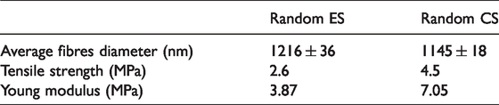
Fibre orientation of random ES and CS were analysed using a similar fibre diameter assessment. All the random nanofibrous from ES and CS showed a similar trend where the nanofibrous were distributed in different angle orientation from 10°–130° as shown in Figure 3(d). However, 56% of random nanofibrous of CS were distributed at 20°–30° angle interval. This indicates that there is a slight alignment in the nanofibrous due to the fibre being stretched and deposited around the spinneret. Next, from Figure 3(e), the random nanofibrous from CS with 4.5 MPa presents higher tensile stress than ES which is 2.6 MPa. But the elongation break of random nanofibrous of ES (82%) was higher than random nanofibrous of CS (10%). This indicates that the random nanofibrous of ES was more flexible than the fabricated fibre in CS. The mechanical properties of fabricated fibres from ES and CS were documented in Table 1.
Characterization of fabricated nanofibrous.
Development of centrifugal electrospinning
Nanofibers producing by traditional techniques deals with toxic solvent and low productivities rate [23]. Traditional system techniques cannot meet the increasing needed of nanofibers. Hence, CES techniques could be one of the new approach in producing nanofiber with high efficiency. Among the traditional techniques, ES and CS are widely used for fibre fabrication. ES capable in fabricating fine fibre with high performance but has low production rate. Contrarily, CS able to produces high fibre production rate, but is unable to produce high performance fibres. By combining the advantages of these two techniques, the CES technique has the ability in produce nanofiber with high efficiency. The CES approach has the benefit of facilitating the production of high-performance nanofiber with high productivity rates. On top of that, CES machine has shown capability in producing anisotropic structural properties in polymer nanofiber [23,24].
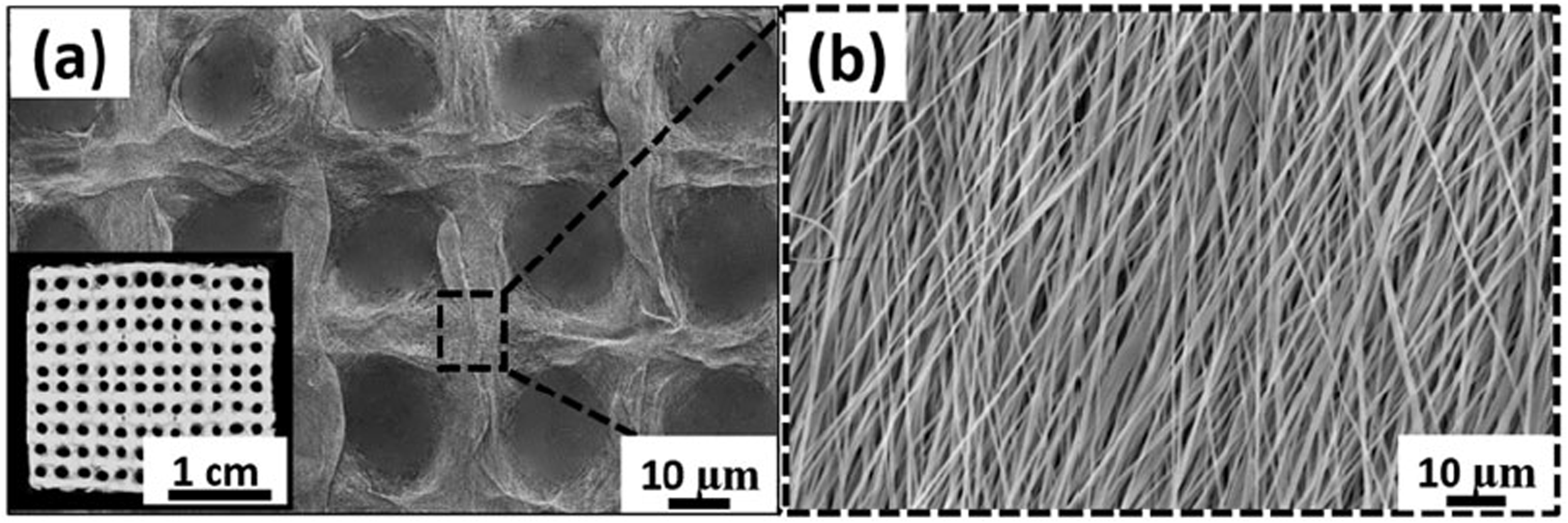
The CES was developed by assembling all the components, including a BLDC motor, syringe stage, syringe stage holder and collector as presented in Figure 4(a). To deliver the high voltage from DC power supply to CES machine, a copper plate and a copper connector were positioned in the vertical direction of the syringe stage holder as shown in Figure 4(b). A wire was connected to the copper plate and linked up to the needle tip to charge the polymer solution. The opposite electrode was subjected to the collector. This design is intended to prevent the CES machine from electrically breaking down during the process of fibre formation. Additionally, utilizing insulator components and increasing the gap between motor and the positive electrode, the process of CES runs smoothly with high voltage supplied up to 30 kV. Figure 4(c) and (d) shows that the fabricated nanofibrous were collected on the circular collector. The fabricated fibres were distributed uniformly in the same area of the circular collector.
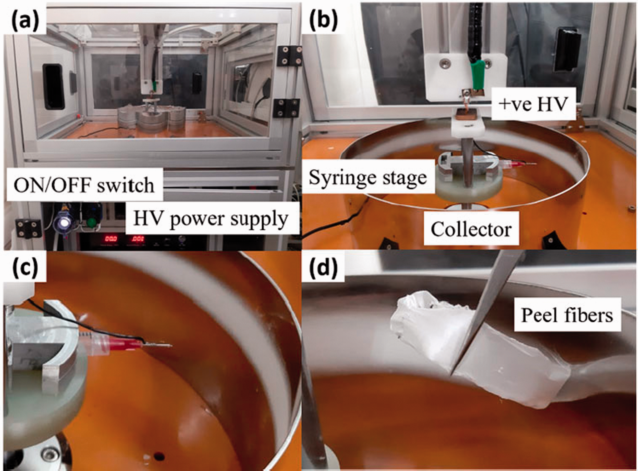
The digital image of (a) developed CES machine (b) closed-up components in CES machine (c) the fabricated nanofibrous (d) closed-up of fabricated nanofibrous.
Mathematical model of the polymeric jet path in centrifugal electrospinning
In the CES process, the polymer jet is subjected towards many forces, including centrifugal force, electrostatic force, surface tension and viscous to form continuous fibres. Figure 5 shows the force acted on the polymer jet during the polymer ejected from the needle tip in the CES process. According to Newton’s second law,


Force analysis act during the CES process as the polymer jet ejects from the needle tip, related to the process in Figure 2(c).
The surface tension of the element


Next, the electrostatic and centrifugal force from electrospinning and centrifugal spinning was added to the integrated system. Referring to the electric field strength from equation (1), the electric field intensity of the CES process is inversely proportional to the distance of the collector when the operating voltage is constant, [25]. E is:
The centrifugal force influence on the process is similar to the equation (2). Finally, by combining equations (2) and (5) to equation (10) into equation (4), the flow of the polymeric jet path in the CES process is
From equation (11), the power of 2 of centrifugal force demonstrated the centrifugal force in the CES process could be the main effect in fabricating fibres. While the electrostatic force with the power of 1 is the second influence on the fabricating fibres. It can be an indication that increasing the centrifugal and electrostatic force will lead to an increase in the length of the polymer jet. Thus, increasing the length of the polymer will lead to decreasing the radius of the leaving polymer jet from the needle tip leading to the formation of thin fibres. Indirectly, this can be related to the needle diameter. The bigger needle diameter used will consequently form a bigger diameter.
The effect of the operating parameter to fabricated fibres by centrifugal electrospinning
Effect on polymer concentration
A series of experiment was conducted to investigate the influence of the polymer concentration on the fibre morphology and diameter. For fair experimental comparison, the rotational speed, operating voltage, and needle size were fixed at 1300 rpm, 10 kV and 0.25 mm, respectively. Figure 6(a) to (f) shows a significant morphology change from 15 wt% to 35 wt%. The fabricated fibre formed from 15 wt% and 25 wt% suffers from the unsolidified fibre and jet fracture. Also, it is observed that the SEM image obtained consists of nonuniform fibres which mixture thinner and bigger fibre diameter. The thinner fiber obtained in ranging 100 nm–200 nm and bigger fibre diameter is 900 nm–1000 nm. This might be due to the use of low polymer concentration and low molecular weight material. By increasing the polymer concentration from 28 wt% to 35 wt%, uniform and continuous fibres were formed as demonstrated in insert Figure 6(c) to (f). The concentration of 25 wt% and 28 wt% presents fibres with random oriented, while highly aligned and uniform fibres were achieved at 30 wt% and 35 wt% polymer concentration. The average fabricated fibre diameter of nanofibrous from 20 wt%, 25 wt%, 28 wt%, 30 wt% and 35 wt% were 409 ± 47 nm, 609 ± 12 nm, 621 ± 17 nm, 637 ± 15 nm, 935 ± 23 nm, respectively. The increase in polymer solution concentration leads to an increase in the average fibre diameter as presented in Figure 6(g). Besides, it can be concluded that the uniformity of fibres increased as the polymer concentration increased. This also correlated to the standard deviation obtained in each polymer concentration. The error bar of standard deviation obtained become smaller as the polymer concentration increases. However, 35 wt% polymer concentration presents a high standard deviation which could be due to the high viscosity. Increasing viscosity hinders polymer jet from being stretched, hence, thicker, and less uniform fibres will be produced. 25 wt%, 28 wt% and 30 wt% polymer concentration have low standard deviation and can be considered to have the most uniform fibre diameter distribution compared to other polymer concentrations. A constant 30 w% polymer concentration with the lowest standard deviation was used to investigate the other parameters on the diameter of the fibres.

SEM image of fabricated fibres at 1300 rpm, 10 kV, 0.25 mm needle size and vary polymer concentration at (a) 15 wt% (b) 20 wt% (c) 25 wt% (d) 28 wt% (e) 30 wt% (f) 35 wt%. (g) Fiber diameter vs polymer concentration.
Effect on the rotational speed
Rotational speed plays an important role in the formation of fibre structure and thinner fibre. To apply constant hydrostatic pressure, the spinning process was executed at a relatively short time [19]. The SEM image of the fabricated fibre at constant operating voltage, needle size and different rotational speed from 700 rpm to 2100 rpm was presented in Figure 7(a) to (f). In general, the morphology of fabricated fibres formed an aligned structure in every range of rotational speed. Although aligned fibres could form at the lower rotational speed of 700 rpm and 1000 rpm, no uniformity of alignments were obtained. By increasing the rotational speed from 1300 rpm to 1800 rpm, highly aligned and uniform fibres were formed. However, increasing the rotational speed up to 2100 rpm, the morphology of fabricated fibres was almost similar to a random fibre. A high stream of rotating airflow around the spinneret and collector occurred at 2100 rpm and above which could lead to random fibres. Also, exposing the ejected polymer jet to the high-velocity airflow causes the polymer jet to lose its solvent quickly resulting in a thicker fibre. This correlated in [13], the researcher varies the rotational speed from 2000 rpm to 5500 rpm and the fibre formed in a random structure and the trends of the average of fibre diameter obtained did not decrease significantly.

SEM image of fabricated fibres at 10 kV, 0.25 mm needle size and vary rotational speed at (a) 700 rpm (b) 1000 rpm (c) 1300 rpm (d) 1500 rpm (e) 1800 rpm (f) 2100 rpm. (g) Fiber diameter vs rotational speed.
The average diameter of fabricated fibres showed a decreasing trend as the rotational speed increased from 700 rpm to 2100 rpm which significantly dropped from 850 ± 25 nm to 298 ± 20 nm as presented in Figure 7. A similar trend is obtained in [26], increasing the rotational speed would decreasing the average fibre diameter. The centrifugal force is increased by increasing the rotational speed as demonstrated in equation (1). Centrifugal force accelerated and stretched out the polymer jet and a higher centrifugal force leads to the extension of the polymer jet which resulted in thinner fibre. This mechanism is also related to the flow rate, where the flow rate will be higher when the rotational speed increases [19]. A higher flow rate impedes the polymer jet drying before solidification occurs and results in thinner fibres [19]. Hence, the rotational speed can be assumed as the main influence parameter in thinning the fabricated fibres.
The standard deviation could indicate the fibre diameter distribution. Among the rotational speed, both of 1300 rpm and 1800 rpm have the lowest standard deviation which is 15 nm. Hence, it is not necessary to increase the rotational speed up to 1800 rpm to obtain an aligned and thinner fibre, but 1300 rpm can be an optimum parameter to form a uniform, aligned and nanoscale fibres. Also, increasing the rotational speed resulted in high production rate and random structure fibre were formed.
Effect on operating voltage
To evaluate the effect of the electrostatic force on the fabricated fibres, a series of experiment was conducted by varying the operating voltage from 3 kV to 20 kV with constant rotational speed and needle size. Figure 8(a) to (f) shows that the morphology of fabricated fibre significantly differed at lower and higher operating voltage. From the experiment at a lower operating voltage of 3 kV and 5 kV, the polymer jet did not fully stretch towards the collector. The polymer jet cannot be formed because the electric field force is weaker than the surface tension. From several SEM image observation, the image consists of mixture nonuniform thinner and bigger fibre diameter. The range of thinner and bigger fibre diameter are 200 nm–400 nm and 900 nm–1100 nm, respectively. Subsequently, when the operating voltage is increased, it will direct the polymer jet to stretch more and elongate toward the collector. Thus, this indicates that the main role of the electric field force is not to thin the polymer jet but to change the direction of the drawing force process of the polymer jet [13]. The fabricated fibre diameter showed a slightly decreasing trend from 1101 ± 36 nm to 591 ± 20 nm as the operating voltage is increased from 3 kV to 20 kV as presented in Figure 8. Increasing the operating voltage, the fibre diameter distribution become more uniform which correlated to the trend standard deviation obtained. The error bar of standard deviation decreases when the operating voltage increased. Researchers used lower operating voltage in fabricating fibre but resulted in a wider range of fibre and non-uniformity fibre [16,26]. Lower operating voltage could lower the electrostatic repulsion forces between the needle tip and the collector which in turn provides weaker drawing stress in the polymer jet and leads in the formation of wider ranges fibre, beaded fibre and non-uniformity fibre [27,28]. Hence, a high operating voltage is required to remove the instability of whipping and strengthening the electrostatic force in the CES process.

SEM image of fabricated fibres at 1300 rpm, 0.25 mm needle size and vary operating voltage at (a) 3 kV (b) 5 kV (c) 10 kV (d) 12 kV (e) 15 kV (f) 20 kV. (g) Fiber diameter vs operating voltage.
A 10 kV and 12 kV can be optimal operating voltage, since uniform, aligned and nanoscale fibres were formed. This can be related to the standard deviation obtained, where both of 10 kV and 12 kV presents the lowest standard deviation. On top of that, there is no significant difference obtained in the average fibre diameter from operating voltage of 10 kV – 20 kV. The average fibre diameter of 10 kV, 12 kV, 15 kV and 15 kV are 637 ± 15 nm, 634 ± 13 nm, 612 ± 18 nm, 591 ± 20 nm. From the results, it can be assumed that operating voltage was the second parameter influenced in fabricating continuous and thinning fibres. By comparing with the effect of the rotational speed, varying the rotational speed will decrease the fibre diameter more than the operating voltage. This correlated to the mathematical model obtained, the electrostatic force with power of 1, the operating voltage could be less influenced in thinning fibre.
Effect on needle size
A comparative experiment in varying needle size from 0.20 mm to 0.40 mm with constant rotational speed and operating voltage was conducted. The fibre morphology is strongly dependent on the needle size shown in Figure 9(a) to (d). The fibres became coarser as the diameter of needle size increased. From the result, the diameter of the fabricated fibre decreased, and the morphology significantly differs as presented in Figure 9(e). Increasing the needle size from 0.20 mm to 0.40 mm, the fibre diameter and standard deviation increased from 305 ± 14 nm to 2814 ± 126 nm. From the standard deviation obtained, the fibre diameter distribution became a smaller range and more uniform with decreasing the needle size. A nanoscale fibre cannot be produced by the smallest needle size (below than 0.20 mm) as it could not form a stable polymer jet droplet. When the needle size is too large, the polymer jet formed thicker which leads to microscale fibres.

SEM image of fabricated fibres at 1300 rpm, 10 kV and vary needle size at (a) 0.21 mm (b) 0.25 mm (c) 0.34 mm (d) 0.41 mm. (e) Fiber diameter vs needle size.
The optimum parameter
From the mathematical and experimental study, an optimum parameter of CES was obtained and summarized in Figure 10(a). When appropriate polymer concentration was chosen, rotational speed presents a higher influence in fabricating continuous and thinner fibres followed by the operating voltage. This correlated to the mathematical and experimental studies. The needle size influences the morphology of the fibres. Bigger diameter of the needle size could lead to a coarser fibre. From the experimental studies, collector distance demonstrated less influence on the fibre diameter and morphology in the CES process. Increasing the collector distance from 10 cm to 12 cm, the fibre diameter increased from 637 ± 15 nm to 684 ± 54 nm. The polymer jet could not deposit to the collector if the collector distance is higher than 12 cm. To solve these difficulties, a higher operating voltage is required when using a bigger collector distance. Hence, it can be concluded that the collector distance is one of the factors in fabricating fibre in the CES machine but not in producing thinner fibres.

(a) Optimum parameter of CES process. SEM and the digital image of (b) random nanofibrous (c) aligned nanofibrous.
Polymer fibre such as PCL-PDMS, PCL-Gelatin and commercialize PCL have been fabricated by this technology. The effect of the process parameter on the fabricated fibre diameter is similar to all the different polymer used. For example, by increasing the applied voltage from 5 kV to 15 kV, the diameter PCL-PDMS fibre decrease from 759 ± 250 nm, 658 ± 310 nm, and 650 ± 228 nm, respectively. Also, the diameter of fibre showed a decreasing trend as the rotational speed increase from 1400 rpm to 2300 rpm which is 806 ± 346 nm, 759 ± 250 nm, and 600 ± 236 nm, respectively [15]. The optimum parameter could be applied not only to presume the diameter of the fibres, but morphology of fibres including beads, fibre-beads, and continuous fibres in the CES process. For instance, it is expected that fibres with beads can be obtained by increasing the operating voltage and bead can be achieved using lower polymer concentration and varying the operating voltage. A uniform and thinner fibres can be obtained by using appropriate polymer concentration, increasing the rotational speed, increasing the operating voltage in practical value, and reducing the needle size. Apart from this, fibres with different morphology could be produced by adjusting the corresponding CES parameters. Continuous random nanofibrous can be fabricated by tuning the process parameter at 2100 rpm, 10 kV and 0.25 mm needle size as shown in Figure 10(a). Meanwhile, a continuous and uniform aligned nanofibrous can be achieved at 1300 rpm, 10 kV and 0.21 mm as presented in Figure 10(b). Nanofibrous scaffold with high mechanical strength, flexibility, and capability to support cell adhesion has potential as a wound dressing scaffold.
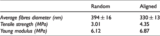
For further comparison as an ideal wound dressing scaffold, the physical, mechanical properties and biological characterization of random and aligned nanofibrous were evaluated. Figure 11(a) presents diameter distribution of random and aligned nanofibrous. The diameter of continuous and uniform random and aligned nanofibrous was distributed at 300 nm–700 nm and 200 nm–700 nm, respectively. Contrary, the diameter of random nanofibrous from ES and CS were distributed at a wide range which is 500 nm–1800 nm and 800 nm–1600 nm as presented in Figure 3(a). Subsequently, the orientation of random and aligned nanofibrous was analysed using a similar fibres diameter assessment. Angle distribution of random nanofibrous from the CES showed a similar trend with ES and CS fibres, where the fibres varied at 0°–120° angle interval. An 88% of an aligned nanofibrous of CES were mainly distributed at 0°–10° angle interval as demonstrated in Figure 11(b). For mechanical characterization, Figure 11(c) presents the stress-strain curve behaviour of random and aligned nanofibrous by CES system. An aligned nanofibrous with 4.35 MPa showed a higher tensile strength compared to random nanofibrous which is 3.01 MPa. No significant difference was observed in the elongation breaks of random and aligned nanofibrous. The elongation breaks of random and aligned nanofibrous were 80% and 73%, respectively. The aligned nanofibrous were easy to be toned because of the tensile force applied along the fibre alignment, which is a perpendicular direction. This revealed that random nanofibrous are more flexible than aligned nanofibrous. Table 2 presents the characterization of random and aligned nanofibrous. By comparing the result with the ES and CS, aligned nanofibrous shows a good candidate as nanofibrous wound dressing scaffold with high tensile strength and appropriate flexibility.

(a) Fibre diameter (b) Angle orientation (c) Stress-strain curve of random and aligned from CES.
Characterization of fabricated nanofibrous.
Cells viability
A biological assay was conducted for further comparison of random and aligned nanofibrous. Figure 12 presents a cell viability of human fibroblast cells in random and aligned nanofibrous from day 1 to day 14. Cells activities were similar from day 1 to day 4 for both random and aligned nanofibrous. Subsequently, the aligned nanofibrous shows a slightly higher absorbance rate 0.72 compared to random nanofibrous 0.6 at day 5. By increasing the culture time at day 7, aligned nanofibrous with 1.37 absorbance rate demonstrates drastic cell viability compared to random nanofibrous which is 1.24. The difference cell viability between random and aligned nanofibrous from day 1 to day 7 are not apparent. The possibilities are the average random fibre diameter is higher than the aligned fibre diameter. The surface roughness of fibre increase with an increment of fibre diameter [29]. The possibilities for this being that random fibres contain a lot of interconnected pores and have rough surface that could promote the adhesion and proliferation of HFS cells. For further comparison, cell viability for random and aligned nanofibrous was observed until day 14. Increasing the culture time to day 14, the cell viability of HFS cell on aligned nanofibrous drastically increased with 2.34 absorbance rate compared to 1.94 for random nanofibrous. It indicated that the aligned nanofibers might have high cell adhesion ability after the initial phase. Considering the experimental condition for random and aligned nanofiber are same, the differences of cell viability could be resulted from the difference structure of nanofibers.
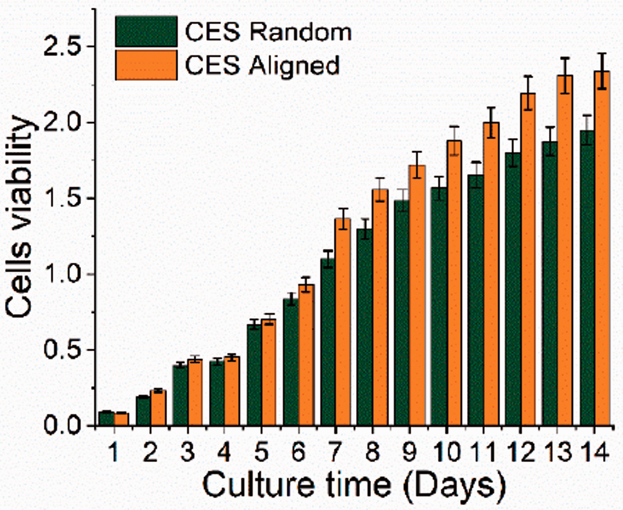
Cells viability of human fibroblasts cells during culture time.
Cells morphology
The morphologies of human fibroblast cells on the random and aligned nanofibrous were determined by DAPI-FDA staining at day 1, 7 and 14. From Figure 13, the cultured human fibroblast cells exhibited morphology without preferred orientation on the random nanofibrous. By increasing the culturing time, fibroblast cells altered their morphology based on the alignment of fabricated aligned nanofibrous as presented in Figure 13(b). Increasing the cultured time, the fibroblast elongated along the direction of aligned fibres. Although the normal shape of human fibroblast cells in the biological assay was spindle shape, there is still a significant difference in cell morphology between random and aligned nanofibrous. From the result obtained, it can be concluded that the orientation of the fibres influenced the cells viability and cells morphology. By increasing the culture time, the cells change their shape depending on the cultured substrates. The influence of alignment fibres on cell morphology has been studied for a variety of cells including osteoblasts cells, muscle cells and stem cell. Previously, it has shown that the cultured cells preferentially elongated in the direction of the highest substrate stiffness as the substrates have been pre-stressed in one direction to yield smooth anisotropic topography [30]. This mechano-transduction explanation for cell orientation on aligned nanofibrous is possible as aligned nanofibrous are known to produce anisotropic mechanical properties within the scaffold [30].

Morphology of human fibroblasts cells at day 1, 7 and 14.
Preliminary studies: 3D nanofibrous scaffold
The traditional nanofibrous scaffold is commonly considered as a 2D nanofibrous scaffold because of the limited thickness. The 3D nanofibrous scaffold allows the cell to proliferate and migrate with their surrounding microenvironment in all three dimensions [31]. For preliminary studies, a 3D nanofibrous scaffold in weave structure was fabricated using copper-mesh as the collector. The structure of weave nanofibrous was formed from aligned nanofibrous as presented in Figure 14(a) and (b).
SEM image of (a) weave nanofibrous (b) closed image of weave nanofibrous.
The thickness of weave nanofibrous was 355.01 µm and the space diameter of the weave nanofibrous was approximately 0.2 cm. The physical, mechanical properties and biological characterisation of weave nanofibrous was evaluated as a wound dressing scaffold. The physical properties weave nanofibrous scaffold are 318 ± 11 nm average diameter and 50% nanofibrous were mainly varied at 0°–30° angle interval. From Table 3, weave nanofibrous scaffold presents a lower tensile strength and elongation with 0.9 MPa and 38%, respectively. Compared to the random and aligned nanofibrous, weave nanofibrous scaffold performed the lowest cell viability at day 7 with a 0.92 absorbance rate. Figure 15 demonstrated the fibroblast cell behaviour on the weave nanofibrous scaffold. From the preliminary result, the fabricated weave nanofibrous is not suitable to be used as a wound dressing scaffold. Parameter, such as space diameter of the weave nanofibrous need to be considered smaller than the cell size. The fabricated weave nanofibrous scaffold could be used in other application such as in medical devices, sensors, and optoelectronic devices.
Characterization of fabricated nanofibrous.


Morphology of human fibroblasts cells at 24 hours on the weave nanofibrous.
Conclusion
Centrifugal electrospinning (CES) technique, which combines the electrospinning (ES) and centrifugal spinning (CS), was developed and applied to produce oriented and diameter-controlled fibres scaffold for stimulating the behaviours of fibroblast cells. A parallel electrode concept was applied to strengthen the electric field between the positive-negative electrode which enhances the process of fibre fabrication. Four parameters, including polymer concentrations, rotational speeds, operating voltages, and needle sizes, are key factors during the scaffold fabrication processes. A uniform and thinner fibre can be obtained by using appropriate polymer concentration, increasing the rotational speed, increasing the operating voltage in practical value, and reducing the needle size. In comparison with the fibres fabricated by the traditional ES or CS, the CES machine only requires 10 kV and 2000 rpm to fabricated fibres scaffold ranging from 210 ± 50 nm to 2814 ± 96 nm. Apart from this, fibres with different characteristics could be produced by adjusting the corresponding parameters. Continuous random nanofibrous can be fabricated by tuning the process parameter at 2100 rpm, 10 kV and 0.25 mm needle size and aligned nanofibrous can be achieved at 1300 rpm, 10 kV and 0.21 mm.
Nanofibrous scaffolds with high mechanical strength, flexibility, and capability have properties to support cell adhesion. The fibre diameter distribution of random and aligned scaffolds is distributed mainly at 200–400 nm. Aligned nanofibrous scaffold demonstrated a high degree of orientation where 88% of the nanofibrous varied at 0°–10°. The angle of the random nanofibrous scaffold was mainly varied at 0°–120°. Aligned nanofibrous demonstrated high tensile strength with 4.35 MPa and appropriate flexibility with 73% of elongation break compared to random nanofibrous. Random nanofibrous scaffold presents appropriate tensile strength and elongation break with 3.01 MPa and 80%. In biological characterization, aligned nanofibrous has exhibited higher human fibroblast cell viability with 2.34 absorbances at day 14 compared to random and weave nanofibrous. The human fibroblast cells elongated along the direction of the aligned nanofibrous. It demonstrated that the behaviour of cells was dependent on the culture substrates. The results suggest that the aligned nanofibrous from the CES machine has potential as a wound dressing scaffold.
Footnotes
Declaration of conflicting interests
The author(s) declared no potential conflicts of interest with respect to the research, authorship, and/or publication of this article.
Funding
The author(s) disclosed receipt of the following financial support for the research, authorship, and/or publication of this article: This work was supported by Ministry of Science and Technology Taiwan [MOST108-2221-E-110-066]; Ministry of Science and Technology Taiwan [MOST109-2221-E-110-023].