
Abstract
The application of carbon fiber/epoxy composites places more requirements on the selection of fabrics to meet the needs of structural components. Due to the large design space for reinforced fabric patterns, the relationship between the reinforcements and properties is essential to further understand. Four typical fabrics were manufactured in this research, named non-interlaced bidirectional fabrics, plain weave laminated fabrics, angle-interlock fabrics and bidirectional angle-interlock fabrics. The structural features of fabrics were analyzed by using representative geometric unit, and the symmetry properties were discussed based on group theory. Vacuum assistant resin transfer molding was adopted to obtain the corresponding resin matrix composite specimens. Quasi-static tensile and bending tests were conducted on these specimens. The stress-strain curves of specimens were illustrated, and the failure characterizations were also analyzed in mesoscopic scale. The results showed that the high crimp of yarns reduced the stability of composites. Both the tensile and flexural properties were affected by the curvature of yarns. The research results provided a theoretical basis for the selection of fabric structure and the application of carbon fiber/epoxy composites.
Introduction
Carbon fiber/epoxy composites are the representative of light weight, high strength and good dimension stability, which are used in new energy development, aerospace, space exploration, construction, automobile and other fields [1]. The categories of reinforcement in carbon fiber/epoxy composites are so various that the selection is considerably difficult [2–4]. The appropriate selection of fabrics can meet the requirements of practical application. It is the key factor that affects the properties of carbon fiber/epoxy composites and reduces the production cost [5]. Hence, it is necessary to investigate the relationship between the meso-structure and properties, and the mechanism analysis need to be further conducted.
Regarding two-dimensional (2D) and three-dimensional (3D) widely used woven components of carbon fiber/epoxy composites, previous studies have reported geometrical model based on group theory analysis [6], specific properties induced by orientations and curvature of reinforced fiber bundles [7], computing models of effective stiffness and strength [8], as well as mathematical model to predict the elastic properties of 3D angle-interlock composites [9]. In addition, the symmetry of carbon fiber/epoxy composites can be further studied, and the mathematical models can be optimized by group theory which will propose in this research.
Considerable researches have reported the mechanical properties of carbon fiber/epoxy composites. Rahmani et al. [10] investigated the effects of fiber orientations, resin types and number of laminates on mechanical properties of unidirectional laminated composites. The results show that the fiber orientation is the main factor affecting the mechanical properties of unidirectional laminated composites, and the elongation is minimal at the orientation of 90 degree. The relationship between fiber volume fraction and flexural properties of unidirectional carbon fiber/epoxy composites were investigated, and the conclusion showed that the flexural strength and modulus were enhanced with increasing fiber volume fractions in an appropriate range [11]. So, non-interlaced bidirectional fabrics (ULF) were introduced in this research due to the higher fiber volume fraction and lower curvature at the orientation of 90 degree. The static and dynamic tensile tests of unidirectional and plain weave laminates were carried out, and both types were strain rate dependent [12]. The float length of yarn in plain woven composites affected the tensile properties along warp direction, which could be used in industrial application [13]. Comparing three different orientation of carbon fiber/epoxy plain woven laminate composites, the (0/90/45/-45) laminates showed the highest tensile strength for the reasonable strain rate range [14]. The tensile property of plain weave composites decreased with the yarn crimps increasing, and the non-linear characteristic of tensile stress-strain curves was closely related to the weaving structure [2]. It could be deduced that the fibers distributed in the tensile direction suffered the main load, and the value of tensile strength was corresponding to the proportion of fibers in tensile direction. In this research, plain weave laminated fabrics (PLF) are also introduced for comparation study. The introduction of ULF and PLF is due to their high degree of automation and wide application. By adjusting the number of layers, the thickness of the components is controlled, but delamination is a fatal disadvantage of these two fabrics.
To solve the delamination, 3D woven composites, including 3D orthogonal woven composites and 3D angle-interlock woven composites, were identified. 3D orthogonal woven composites were found to have both greater strength and modulus in tension and compression, but the angle-interlock woven architecture was found to outperform the remaining 3D architectures [15]. Umer et al. [16] studied the effect of weaving architecture on 3D woven composites, and the results showed that the flexural strength and modulus were higher along the weft direction due to fiber alignment. Comparative studies of 2D and 3D carbon fiber/epoxy composites were also presented in the past researches. Four different laminate composites were manufactured and evaluated by tensile tests, and the plain weave laminates presented the highest values of tensile strength. The adequate combination of the matrix and the reinforcement in composites manufacture was the most important factor affecting the mechanical properties [17]. 3D woven composites have considerably superior impact resistance, delamination resistance and dynamic mechanical analysis behavior as compared to unidirectional and 2D counterparts [18]. The influence of structural factors including crimp and yarn linear density was discussed, and the results indicated that the least crimp percentage existence in 3D fabrics led to better tensile properties [19]. The flexural properties of 3D woven composites and 3D laminated plain composites were studied by vibration analysis, and the failure of 3D woven composites was mainly fiber fracture and showed a more beneficial than the classic laminate (mostly delamination) [20]. The comparative study of 3D interlock woven composites was developed considering the presence of higher crimp factor, and the bidirectional interlock composites were recommended for applications due to their improved mechanical properties [21]. The waviness of the load-carrying fibers was mainly influenced the mechanical properties of 3D woven composites, and the angle-interlock weave exhibited the highest properties among six different weave types [22]. Two typical 3D woven fabrics, named angle-interlock fabrics (2.5DF) and bidirectional angle-interlock fabrics (D2.5DF), were manufactured according to the aforementioned reviews. The properties of 2.5DF in warp and weft directions are quite different, but the structural features and properties of D2.5DF are consistent in these two directions.
The curvature of load-carrying fibers in warp direction influence the tensile and flexural properties of carbon fiber/epoxy composites reinforced with 2D and 3D fabrics. The aim of this research is to conduct a comparative study, and the mechanism analysis is also proposed to explain the failure modes. Four typical fabrics are manufactured, named ULF, PLF, 2.5DF and D2.5DF. The geometric structures of these fabrics are analyzed based on group symmetry. Vacuum assistant resin transfer molding (VARTM) is used to obtain the counterparts. Four typical carbon fiber/epoxy composites, named non-interlaced bidirectional composites (UL), plain woven laminated composites (PL), angle-interlock woven composites (2.5D) and bi-directional woven composites (D2.5D) are conducted by quasi-static tensile and three-point bending tests. The stress-strain curves of composites are obtained, and the failure characterizations of specimens are analyzed in mesoscopic scale. The influence of crimp in load-carrying fibers on the tensile and flexural properties is discussed.
2. Geometry analysis
The cross-sectional shape and crimp of yarns in fabric reinforcements are the factors that mainly influence the mechanical properties of composites. In this section, the geometric structures are analyzed, including the symmetry property and curvature. The difference of specimens with various fabric structures is analyzed, and the parameters of fabric reinforcements are also discussed.
The details of four typical fabrics are illustrated in Figure 1. The schematics of fabrics are displayed, and the cross-section is perpendicular to x-axis. The cross-section of representative geometric unit is shown in the dotted box. Elliptical yarn cross-section is supposed in this research. Twist is also an important factor affecting fabric structure, and the yarns in these four typical fabrics owe the same twist. The pictures of cross-section are obtained by optical microscope. The gray areas indicate the yarns along the warp direction, while the dark areas indicate the cross-section of weft yarns. The structural parameters of warp and weft yarns are identical. ULF is shown in Figure 1(a), and the yarns along warp and weft directions are distributed alternately without interlacing. Figure 1(b) shows the PLF, and the warp and weft yarns are aligned into the relative directions. The elliptical shape of cross-section is appeared. Both ULF and PLF are laminated fabrics, and no reinforced fibers exist in z-direction. Figure 1(c) shows the schematic of 2.5DF. The yarns in warp direction are interlaced by layers, and the yarns in weft direction are straight. Figure 1(d) illustrates the sketch of D2.5DF. The yarns both in warp and weft are interlaced layer-by-layer, and the curvature of yarns is the same in both directions. Both 2.5DF and D2.5DF are 3D woven fabrics, and the layers are connected by fibers. The pitch length of 2.5DF and D2.5DF is closely to each other and is also similar to PLF. The cross-sections of ULF and D2.5D are normalized, but PLF and 2.5D show the low determinacy.

Schematic of four typical fabrics and pictures of cross-section.
2.1 Symmetry property
Representative geometric units are used to predict the geometrical and mechanical properties of symmetric carbon fiber/epoxy composites. Based on the repeating units, the fiber volume fraction can be predicted by geometric model, and the relationship between fiber volume fraction and geometric parameters can be obtained. The stiffness matrixes of fiber systems in representative geometric units can be calculated by homogenization method. Thus, the symmetry analysis of representative geometric units is necessary.
In performance prediction model, carbon fiber bundle is often supposed as transverse-isotropic material [23], and the fabrics can be obtained by the translational symmetry of the basic repeating unit [6]. The introduction of space group theory can greatly reduce the complexity of model calculation. In this research, the four typical fabric reinforcements are analyzed based on group theory. As shown in Figure 2, the models of four representative geometric units are proposed. Figure 2(a) displays the ULF, and the point group 222 (HM international standard symbol) can be used to describe the symmetry properties. The point group 222 can be recorded as

Symmetric geometric relationship of equivalent yarn segments based on group theory.
2.2 Model analysis based on group theory
2.2.1 Crimp analysis
The crimps of yarns in specimens with various fabric structures are different, which mainly due to the structural features of fabrics. The relationships between processing parameters and geometrical structures have been discussed in previous researches [24]. Here crimp is adopted as shown in Formula (1)

The length of curved yarns is relevant to the cross-sectional shape of yarns. Ma et al. [9] discussed the influence of deformation coefficient on the geometrical and mechanical properties of 3D woven composites. The deformation coefficient k was defined as the ratio of the semi-axial lengths of the yarn oval-shaped section. It could be obtained that the physical length of the yarn and the corresponding wavelength were both related to the deformation coefficient. The crimps of yarns in specimens was the function of k. The geometrical and mechanical models were developed for the prediction of modulus of 3D woven composites with crimp fabrics [23–25]. The existing theory could calculate the degree of crimps in four kinds of fabrics.
2.2.2 Geometrical model
As shown in Figure 3, representative geometric units of these four typical fabrics are proposed, and the geometrical relationship is also displayed. The internal units of four kinds of specimens are established to express the relationship between fiber volume fraction and geometric parameters. In Section 2.1, the relationship between yarn segments in each unit is analyzed based on group theory. The length of single yarn segment can be calculated, as well as the volume of fibers in each unit. Figure 3(a) shows the cross-section of the unit with ULF. The fiber volume


Diagram of representative geometric units.
The total volume of representative unit is U0.

The representative volume unit of PLF is established, and the cross-section of unit is displayed in Figure 3(b). The curved yarn segments can be regarded as two arc length l with the angle σ. The fiber volume


Set w and h represent the width and height of the representative unit. The total volume of unit is U1.

Figure 3(c) shows the position of weft and warp yarn segments in the unit with 2.5DF. The single warp yarn segment can be divided into three parts l1, l2 and l3, and a1 and b1 represent the length of long and short axes of weft yarn cross-section, separately. Two points of tangency M (x1, y1) and N (x2, y2) of straight-line segment and two ellipses can be obtained, and satisfied the following relation.

The fiber volume

As shown in Figure 3(c), W, Q and P represent the width, length and height of the representative unit. The total volume of unit is U1.

Figure 3(d), the representative unit of D2.5DF is proposed. Ma et al. [9] have been elaborated the geometric structure. Formula (9) is introduced

Fiber volume fraction can be finally obtained by Formula (10)

2.2.3 Prediction models of elastic constant
The resin matrix materials in composites are regarded as isotropic, only two independent engineering elastic constants, Em and vm. The relationship between stiffness matrix [C]
m
and flexibility matrix [S]
m
is proposed in Formula (11)

In this research, the global coordinate system is recorded as o-123, and the local coordinate system is o-xyz. Fiber yarns are considered to be transversely isotropic materials. 1-axis is coincided with x-axis, and o-23 plane is isotropic plane. Five independent engineering elastic constants are contained in stress-strain relation, and
In UL, specimens only existed the straight fiber bundles along the coordinate axes. The other three typical specimens named PL, 2.5D and D2.5D contained the curved fiber yarns. The lengths of these fiber bundles were calculated according to Formula (4), (6) and (9). For the fiber bundles with different orientations, its total stiffness matrix is a function of spatial coordinates. According to the stiffness average method, the stiffness matrix [C]
C
is expressed by the integral average value of the curved fiber length Lr, that is
The stiffness matrixes [C]
Ci
of other curved fiber bundles could be calculated according to transformation matrixes

Based on the hypothetical linear model of Voight, the composite stiffness matrix is deduced by homogenization method

The flexibility matrix [S] is

The elastic constants are

Experiment
Materials and specimen preparation
Carbon fiber/epoxy composites in this research are made of T700-12K carbon fibers reinforcing epoxy matrix. The properties of T700-12K carbon fibers were obtained by the test report produced by Beijing University of Chemical Technology. The epoxy resin and curing agent were both provided by Wells Advanced Material Co., Ltd. The parameters of T700-12K carbon fibers, epoxy resin GE-7118A and curing agent GE-7114B are listed in Table 1.
Parameters of component materials.

VARTM technique is used for the resin injection to obtain the counterparts. The principle analysis of VARTM process have been proposed in reference [27]. Vacuum bag and mold are both used to make the dry fabric in vacuum environment. The epoxy resin GE-7118A is mixed with curing agent GE-7114B in mass ratio 10:3. The resin is fully infiltrated into the dry fabric by vacuum pump through flow medium, and the surplus resin is collected in trap box. The specimens are curing at room temperature for 24 hours. The water jet scalpel is introduced to manufacture the specimens of carbon fiber/epoxy composites. The dimensions of specimens in tensile and three-point bending tests are illustrated in Figure 4(a) and (b). Four typical specimens, named UL, PL, 2.5D and D2.5D, are produced. Figure 4(c) shows the picture of tensile specimens, and the two ends were wrapped with copper to avoid the slipping and stress concentration around the clamps. Reduce the probability of invalid specimens. Figure 4(d) shows the four specimens prepared for three-point bending tests.

Details of final specimens: (a) dimension of tensile specimens; (b) dimension of bending specimens; (c) pictures of tensile specimens; (d) pictures of bending specimens.
Quasi-static tensile tests
The quasi-static tensile tests and three-point bending tests were conducted in the laboratory of Nanjing University of Aeronautics and Astronautics using a universal testing machine. In tensile tests, the cross-head speed was 2 mm/min according to the standard ASTM D638-14. The loading procedure of tension was very slow, and equivalent to quasi-static. The force only produced “internal effect (deformation)” for specimens, while “external effect (acceleration)” could be ignored. The temperature was around 25 °C ± 5 °C during the test. The extensometer was adopted to record the displacement changes in minute scope. The specimen center line coincided with the loading center line of the test equipment to avoid the influence of additional shear force, bending moment and torque on the specimen during uniaxial tension. The load-displacement curves, elongation, tensile strength and modulus could be obtained. Tensile strength 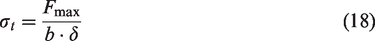
The tensile modules of elasticity Et can be calculated by Formula (19)
Three-point bending tests
According to the standard ASTM D7264D7264M, the speed of the indenter was 2 mm/min in three-point bending test, and the span-to-depth ratio of 16:1 was used without interlaminar shear. The tests were conducted at the temperature around 25 °C ± 5 °C. Each test result in this research was the average of five repeats. The load-deflection curves, maximum load and deflection to failure could be deduced. Flexural stress can be obtained by Formula (20)
Formula (21) can calculate the flexural modulus of elasticity
Results and discussion
Tensile properties analysis
Quasi-static testing datum of four types of carbon fiber/epoxy composites are listed in Appendix 1. Tensile strength and tensile modulus of elasticity were calculated by Formula (18) and (19), and the average values were also obtained. The values were corrected to two decimal places. The width and length of the effective segments were measured at two ends and central part, and the average values were also deduced. As shown in Figure 5, the tensile strength and modulus of four typical composites are displayed. The error bar is introduced to illustrate the distribution range of strength and modulus.

Tensile strength and modulus of four typical specimens.
In this research, the parameters of carbon fiber yarns in four typical fabrics are the same, and the cross-sectional shape is supposed as ellipse. The difference of deformation coefficient k in these fabrics could be ignored, and the comparative study could be proposed. Considering the degree of crimps in these specimens, the length of curved yarns in represent unites were deduced. According to Formula (1), (4), (6) and (9), the crimps of four typical fabrics could be calculated. The order of crimp values is as follows: UL<PL<D25D < 2.5D. Due to the same structural parameters of yarns in warp and weft directions, the values of crimp in PL and D2.5D are similar. The wavelength of these two typical composites is the length of adjacent weft yarns, and the amplitude is the thickness of adjacent layers. The yarns in UL are straight, and the value of crimp is constant. For 2.5D, the yarns in weft direction are straight, and the crimps of warp yarns show the high amplitude. The following results are obtained:
The tensile modulus of UL shows the highest due to the lowest value of crimp, and the physical length of the yarn along its path is equaled to the corresponding wavelength. By contrast, 2.5D exhibit the lowest modulus owing to the high crimp in warp direction. For PL and D2.5D, both the tensile strength and Young’s modulus are similar, and the results owe greatly to the similar crimps of yarns in specimens. As for composites without the fiber reinforcement in interlaminar, the tensile strength and Young’s modulus of PL are all lower than those of UL. For composites with z-directional yarns, the tensile strength and modulus of 2.5D are the minimum of four kinds of specimens. Compared with the typical composites, UL and D2.5D presented the superior tensile strength, and UL and PL presented the higher tensile modulus of elasticity.
Figure 6 shows the stress-strain curves of four representative composite specimens. The results indicate that the curve slope of UL is the largest, and the value of PL is similar to D2.5D. The value of curve slope in 2.5D is the lowest which convinces with the calculation in Appendix 1. The variation range of tensile modulus in UL is smaller than PL ones, and it indicates that the initial modulus of UL is the highest due to the low crimp in fabrics. The curves of UL and PL are linear before reach 0.02 strain, and the slopes of curves decrease gradually. And then, the stress cut down after the tensile strength reached the maximum.

Stress–strain curves of specimens in tensile tests.
2.5D and D2.5D within high crimp in corresponding fabrics presented the instability in quasi-static tensile tests. The results show that the curve of D2.5D is smoother than the 2.5D ones. It can be obtained that the curves of D2.5D and PL show the same slopes owing to the similar crimp. The variation range of tensile modulus in D2.5D is smaller than UL and PL, and D2.5D present the stability in tensile tests due to the meso-structure of fabrics. On the contrary, 2.5D is extremely unstable, and the values of load and displacement are both bounced before reach the maximum tensile strength. In a word, the stress-strain curves increase linearly with the load increasing at the beginning of the test. When the load reaches a certain value, the curves exert variously nonlinear until the maximum values. These results indicated that the crimps of load-carrying yarns in composites played a significant role in tensile properties. The tensile strength and modulus in load-carrying direction are decreased with the increase of crimp value.
Flexural properties analysis
Three-point bending test data of four kinds of carbon fiber/epoxy composites are listed in Appendix 1. Three-point bending tests were conducted along the direction of weft yarns. The indenting roll was perpendicular to the warp yarns. Three-point bending tests were conducted on universal testing machine, and the span-to-depth ratio was 16:1. The width w (mm) and thickness h (mm) of the cross-section in specimens were both measured. The applied force P(N), flexural stress

Flexural stress and modulus of four typical specimens.
The maximum applied force of UL and PL in bending tests are both higher than 2.5D and D2.5D. It is mainly due to the high crimp of 2.5D and D2.5D in warp direction. The flexural stress and modulus of 2.5D are minimum compared with other kinds of specimens. The flexural stress and modulus of UL are maximum due to the low curvature, and the fibers in the specimens better suffer the bending load. On the contrary, the high crimp of 2.5D in warp direction makes the fibers unable to bear the most of the bending load. The flexural modulus of D2.5D is similar to PL, which are both lower than UL ones. The main reason is the aforementioned order of crimp value in these specimens. The results further validated the influence of crimps on flexural properties of composites.
Figure 8 shows the flexural stress-strain curves of four kinds of specimens. Each curve is a representative specimen for each kind of composites, and can provide a comprehensive depiction of the damage initiation and growth. By comparison with four kinds of specimens, the stress-strain curves clearly show obviously different trends. The curves indicate that the flexural properties of UL and D2.5D are more stable than PL and 2.5D, separately. The variation range of flexural modulus of UL and D2.5D specimens are so small that could be ignored during the whole tests. For PL and 2.5D, the slope of curves did not reach the maximum value at the beginning of loading. With the increase of applied force, the slope value gradually increased and reached a certain value. The most changing in term of curve slope is PL, and the initial modulus of PL is relatively low.

Stress–strain curves of specimens in three-point bending tests.
The stress-strain curve of UL is smooth than other typical specimens due to the low curvature of yarns both in warp and weft directions. The results show that the curvature of yarns in fabrics influenced the flexural properties, and the stress-strain curves of PL, 2.5D and D2.5D are bounced before reach the maximum applied force. Comparing with UL and PL, 3D composites reinforced by angle-interlock fabrics remain higher stress after failure, and sudden load reduction are occurred in UL and PL specimens. The reason for this phenomenon is that 2.5D and D2.5D owed the fiber reinforcement in interlaminar. Compared 2.5D and D2.5D, the latter exhibit the better flexural properties due to the low curvature of reinforced fiber bundles. In conclusion, the initial modulus of carbon fiber/epoxy composites are affected by the structural features.
Analysis of failure characterizations in tested specimens
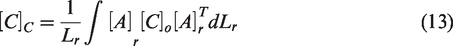
The failure characterizations of specimens could be analyzed to discuss the inherent dissimilarities. As shown in Figure 9, the failure modes of carbon fiber/epoxy composites under tension load are displayed. According to the difference of structural features in fabrics, the macroscopic behaviors of four typical specimens show the distinct characteristics. For UL, PL and 2.5D, the length of fiber pullout is longer than D2.5D. The difference of failure characterization between PL and 2.5D could be ignored due to the same fracture. Compared with Figure 6, the results show that 2.5D exhibit the poor stability when reach the maximum applied force, owing to the zigzag shape in stress-strain curves.
Macroscopic failure characteristics of four typical specimens under tension loading.
To further discuss the internal structures of fabrics, the cross-section of specimens at fracture surfaces were also observed under an optical microscope, as shown in Figure 10. Combining Figures 9 and 10, the typical failure modes of these specimens could be obtained. For UL and PL, delamination dominated the main form of failure due to the structural features in fabrics. Without fibers reinforcement in interlaminar, the laminated composites possess the poor out-of-plane properties. Figure 10 shows the obvious interlaminar cracks, and the fractures are irregular. For 2.5D and D2.5D, the fiber reinforcement in interlaminar provide the strength and stiffness in the out-of-plane direction. There are few interlaminar cracks at the fractures. The cracks of epoxy resin both in 2.5D and D2.5D are regular, and the breakages of fibers are irregular. The results show that the carbon fibers in specimens suffer the most of the load. The tensile modulus and crimp of PL and D2.5D are similar, but the fracture surfaces show the great difference. The performance of D2.5D inherited the advantages of PL and enhanced the interlayer bonding performance. It is validated by the experimental results.

Cross-section of four typical specimens under tension loading.
Three-point bending tests along the warp direction were conducted in this research, and the cross-section of four typical composites were observed under an optical microscope. As shown in Figure 11, the failure modes in cross-section of specimens under three-point bending load are displayed. For UL, the notch in tensile surface appeared obviously, and accompanied by delamination. The cracks in PL are through the thickness, and the results are mainly due to the lack of fibers reinforcements in interlaminar. There is no obvious cracks and fractures in both the tensile and compress surfaces. Only white point appeared in the tensile end, and the fibers in specimens cannot bear the bending load to the maximum extent. For D2.5D, the failure modes are similar to UL, but without obvious delamination. It can be deduced that the flexural properties of 2.5D and D2.5D are better than the ones of UL and PL. The morphology reveals the vital function of fibers reinforcement in interlamination. The results indicate that the crimp of load-carrying yarns mainly determine the tensile and flexural properties of composites.
Cross-section of four typical specimens under bending load.
Conclusion
Various fabric structures were developed to satisfy the application of carbon fiber/epoxy composites. More requirements on the selection of fabrics were proposed, and this research conducted the tensile and flexural properties of four typical carbon fiber/epoxy composites. The structural features of fabrics were analyzed based on group symmetry, and the repeating units were presented. The crimps of each reinforced fabric were analyzed. The specimens of four typical composites were prepared, and quasi-static tensile (along warp direction) and three-point bending tests (along weft direction) were conducted. The test data and stress-strain curves of specimens were obtained, and the failure characterizations of specimens were analyzed in mesoscopic scale. Results indicated that the crimps of yarns in specimens had the vital role on the tensile and flexural properties. The following results obtained: For tensile properties, the crimp of yarns in tensile direction dominates the tensile properties. The interlaminar yarns do not exhibit the important effect in tensile tests, but paly the important role to resistant delamination in bending tests. UL and PL could be used in the application of components bearing the unidirectional load and low delamination requirements. 2.5D and D2.5D could be introduced to resistance the delamination, but D2.5D show the better performance both in warp and weft directions. The structural features of fabrics have the key role in tensile and flexural properties of composites. Fibers reinforcement in interlaminar have the vital role to prevent delamination, and the crimps of yarns in fabrics influence the stability of composites. The higher requirements for interlaminar mechanical properties, the lower curvature is selected to enhance the stability of composites. For the application under different working conditions, different fabrics are selected to satisfy the requirements.
In this research, the influence of fabric structure on the tensile and flexural properties was analyzed. Geometric models and mechanical models could be established based on group theory. The numerical analysis is the further work, and the comparison study of dynamic mechanical properties need to be proposed. Moreover, the initial modulus of composites with high crimp yarns show the poor stability. To eliminate the difference in its infancy, the optimized fabrics could be introduced in the following research.
Footnotes
Declaration of conflicting interests
The author(s) declared no potential conflicts of interest with respect to the research, authorship, and/or publication of this article.
Funding
The author(s) received no financial support for the research, authorship, and/or publication of this article.