
Abstract
The catenary system was an important part of electrified railway, which provided traction power for electric trains. Cu/CF/phenolic resin contact strip (CFRCS) had been designed with excellent mechanical strength and electrical conductivity. The properties of CFRCS and the pure carbon contact strip (PCCS) were also compared. It could be found that CFRCS not only had higher impact strength than PCCS, but also had lower resistivity, which was favorable for current transmission. This paper analyzed the wear behavior of contact strips from two aspects of wear data and abrasive dust, which was mainly determined by the current and its components. The current-carrying wear mechanism of CFRCS was mainly arc erosion wear, oxidation wear and adhesive wear, while that of PCCS was oxidation wear and arc erosion wear.
Introduction
Pantograph slide plate–catenary system was an important part of electrification system in railway technology developments. It provided traction power for trains and played an important role in speeding up trains [1,2]. Most catenary system was copper contact wire, and a special contact belt friction pair was required to reduce wear on the wires [3]. In recent years, the contact slide plates for electric locomotive were mainly copper-based powder metallurgy slider, aluminum alloy carburizing slider, carbon contact strip and composite slide plates. The metal slider has good electrical conductivity, which can reduce the phenomenon of arc discharge, but the adhesion wear between metal slider and copper wire is seriously [4]. Due to the self-lubricating effect, the wear of carbon sliders on the wire is small. However, their applications had been limited by their inferior mechanical properties. Therefore, high-performance composite pantograph slide plates had become a research hotspot [5–9]. For example, carbon fiber (CF) reinforced composites [10–13] were primarily developed and designed for friction structural applications due to their excellent performance [14,15]. Xian and Zhang investigated the friction characteristics of chopped carbon fiber-reinforced polyetherimide composites and pointed out that owing to the existence of carbon fiber, the friction coefficient of composites reduced and the wear resistance improved [16]. Yang et al. fabricated CF fabric reinforced copper composite by a vacuum infiltration technique and the composite appeared greater wear resistance than the Carbon/Copper strip without CF [17].
The mechanical properties of composites reinforced by carbon cloth are better than chopped carbon fiber materials, but it is easy to cause interlayer cracking under current-carrying wear condition. To solve this problem, hybrid fiber reinforced sandwich composite was used in this paper. The surface modification of carbon fiber also needs to be carried out to enhance the degree of bonding between resin and fiber. The modification method must be environmentally friendly and suitable for mass treatment. The surface modification methods of carbon fiber include high temperature heat treatment, chemical oxidation, electropolymerization, vapor deposition, plasma etching, chemical coating, corona treatment and grafting polymerization. Since the carbon fiber used in the experiment is the carbon fiber cloth, the surface modification method of carbon fiber needs to be simple and controllable. Liquid phase oxidation is a method that liquid phase medium is used to oxidize and modify the surface of carbon fiber. This method is relatively mild and will not lead to excessive pits and cracking of the fiber. Oxidation treatment can change the physical and chemical properties of the surface of the fiber. In addition, the surface of carbon fiber is polar, while the surface of phenolic resin is non-polar, so its interface adhesion is poor. Silane coupling agent has dual functional groups, which can bond resin and carbon fiber respectively, and can effectively improve the bond between resin matrix and carbon fiber.
Moreover, some researchers had found that the wear rate of the contact strip is proportional to the current and arc discharge [8,14,18–20]. A better understanding of the wear mechanism of the carbon fiber reinforced contact strip was also required.
According to the working conditions of pantograph strip, Cu/CF/phenolic resin contact strip (CFRCS) was developed to improve the mechanical properties of pure carbon contact strip (PCCS). The wear mechanism of composite under different current intensity was studied by block-on-ring type wear test. And finally, the wear mechanism of CFRCS and PCCS is also studied.
Experimental
Materials
Carbon fiber fabric (CFF) and chopped carbon fiber (the tensile strength of 3.6 GPa) were obtained from Weihai Guangwei Group Co., Ltd. in China. Pure carbon contact strips (PCCS) was purchased from CRRC Zhuzhou Locomotive CO., LTD. Phenolic resin and Nitrile rubber (NBR) were manufactured by Jinan Shengquan Group Share Holding Co., Ltd. and Nanjing Shengdong Chemical Engineering Co., Ltd. (China), respectively. Flake graphite (0.5∼10 μm) were produced by Qingdao Tianhe Graphite Co., Ltd. in China. Cu mesh: main electric conductive phase, pore diameter size and the thickness were 3.16 mm × 6.30 mm and 0.48 mm, respectively. (3-Aminopropyl) trimethoxysilane (APS, silane coupling agent), sulfuric acid, hydrochloric acid, acetone and ethanol are analytical grade and purchased from Aldrich.
Specimen preparation
The surface modification methods of carbon fiber were liquid phase oxidation and coupling agent treatment to improve the interfacial adhesion and the properties of the resulting composite materials, which have been proved in our previous work [21]. The details were as follows:Firstly, fabrics were washed in acetone to remove surface adhesives and contamination, and then dried. Secondly, CFF was heated in 40 wt.% H2SO4 and 15 wt.% KClO3 for 120 minutes. The CFF was thoroughly washed with deionized water and then dried. The modified CFF was finally immersed in the 1 wt.% hydrolyzed APS solution to coat silane coupling agent for 4 hours and dried.
The preparation process of CFRCS was as follows. The formula was: Cu mesh 15 wt.%, Cu power 5 wt.%, carbon fiber cloth 17 wt.%, chopped carbon fiber 5 wt.%, phenolic resin 32 wt.%, graphite 22 wt.%, NBR 3 wt.% and APS silane coupling agent 1 wt.%. The modified phenolic resin, flake graphite, copper powder, NBR, chopped CF, silane coupling agent and anhydrous ethanol were mixed and evenly coated on the CFF and dried. The CFF and copper mesh were cut into the size of mold cavity and filled into the mold in order, shown in Figure 1. The composites were pre-press and then hot-press in mold under the pressure of 170 °C and 100 MPa for 30 min.

Schematic of sample preparation process and the high-speed sliding wear tester under current.
Test apparatus
The wear surface micrographs of carbon fiber and contact strips were analyzed by SEM (SU-70) with an acceleration voltage of 15.0 kV. Morphology and surface roughness of the CF were determined by Atomic force microscopy imaging using a Bruker ICON AFM system in ScanAsyst mode (Bruker, Santa Barbara, CA). Atomic Force microscope (AFM) imaging samples were prepared by UV glue adhesive bonding CF to a clean silica substrate. The expression of carbon fiber surface functional groups was carried out by VG-Scientific-ESCA-LABMK-II XPS spectrometer. The FTIR of the carbon fiber was measured on the Bruker Alpha VERTEX-70 infrared spectrometer. Rigaku D/max-RC wide-angle X-ray diffractometer was used to analyze the crystal structure. The accelerating voltage was 40 KV, the current intensity was 50 mA, the scanning diffraction Angle was set to be between 5° and 90°, and the scanning speed was 3°/min.
The interaction performance bending strength of composites and the mechanical properties of CF were measured by universal machine. The impact performance test was carried out by XJJ-50 impact testing machine and the size of sample is 120 mm × 15 mm × 10 mm. The wear performance of CFRCS and PCCS on copper under current was studied by HST-100 high speed electrical wear tester (the schematic of friction pairs was shown in Figure 1). The wear materials were processed into the 12.0 mm × 9.0 mm × 20.0 mm. Pure copper (φ = 70 mm) were evaluated using a pin-on-disc friction and wear machine. The preparation involves polishing impurities and uneven surfaces to obtain a smooth but not highly polished surface. Friction and wear under current was carried out under the conditions of room temperature, the current density of 0–100 A/cm2 and the normal load of 40–90 N. The sliding velocity of the composite on the copper plate is 20–300 km/h to simulate the relative speed of the pantograph slide plate–catenary system. The resistivity of the composite was measured by using four-point probe technique with the sample size of 15 mm × 15 mm × 4 mm.
Due to the different types and densities of samples, the degree of wear was expressed by the volume wear amount and length under unit load Ws (mm3·N−1·m−1), which was calculated by equation (1)
Where ΔW was wear value (g), μ was friction factor, F was the loading (N), ρ was density of contact strip (g·cm−3), r was the radius distance between the axis of grinding wheel and sample (m), as shown in the green line of Figure 1. μ was friction coefficient and reported by computer. v was the rotating counts of the grinding wheel (r/s) and t was worn time (s).
Results and discussion
Properties of modified carbon fiber
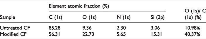
Due to the surface chemical inertia, fewer functional groups and lower surface energy, it is difficult for CF reinforced composites to show ideal interface adhesion [11]. In this work, liquid-phase oxidation and coupling agent treatment are used to enhance the surface reactivity of carbon fiber to further enhance the interface properties of composite [20]. The mechanical properties of chemically modified carbon fiber are studied by uniaxial tensile test (Figure 2(b)). The surface morphology of modified carbon fibers is characterized by SEM (Figure 2(a) and (d)), XPS (Figure 2(e)) and AFM (Figure 2(c) and (f)). Due to the activation of acid and APS coupling agent, there are some narrow grooves on the fiber surface and APS membrane along the fiber length. Both chemisorption and physical adsorption are observed in the modification of CF and resin by APS coupling agent. Up to AFM, the surface roughness increases significantly from 32.6 nm to 68.8 nm after acids and APS modification. Moreover, the change in roughness can be seen from the height difference and Rq data. In the Figure 4(c), the height difference of the sample surface is 24.2 nm (Rq = 3.57 nm). In the Figure 4(f), the height difference of the sample surface is 33.4 nm (Rq = 4.71 nm). The tensile strength of oxidized CF decreases slightly (Figure 2(b)). Combined with the data of XPS, the content of oxygen functional groups increases obviously (Table 1). The process has the advantages of mild treatment conditions, low cost, good fiber intensity and effectively increasing the number of active functional groups to improve interfacial bonding force of contact strip. In addition, the silane coupling agent including in the composite formula is easy to be coated on the surface of copper powder, which is conducive to interface adhesion [22]. FTIR can characterize the active functional groups on the surface of the fiber, shown in Figure 3. Oxygen-containing groups can improve the surface activity of the carbon fiber and make it more compatible with resin. After acid treatment, an absorption peak appears near 3446 cm−1 in the infrared spectrum, which is a characteristic peak of hydroxyl group. In addition, the absorption peak of carboxyl and double bond stretching vibration near 1630 cm−1 is significantly enhanced. Acid can etch the disordered graphite structure on the CF surface, break large graphite layers, and oxidize unsaturated carbon atoms at edges and corners, thus increasing the acidic functional groups on the surface. In addition, the absorption vibration peaks of hydroxyl and silica-oxygen bonds can be clearly seen on the infrared curve of the carbon fiber treated by acid oxidation and APS.

The properties of modified carbon fibers: carbon fiber surface morphology (a) and (d), fiber mechanical properties (b), surface structures by XPS (e) and the surface roughness tested by AFM (c) and (f).
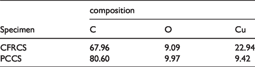
Element analysis on the surface of carbon fibers by XPS.
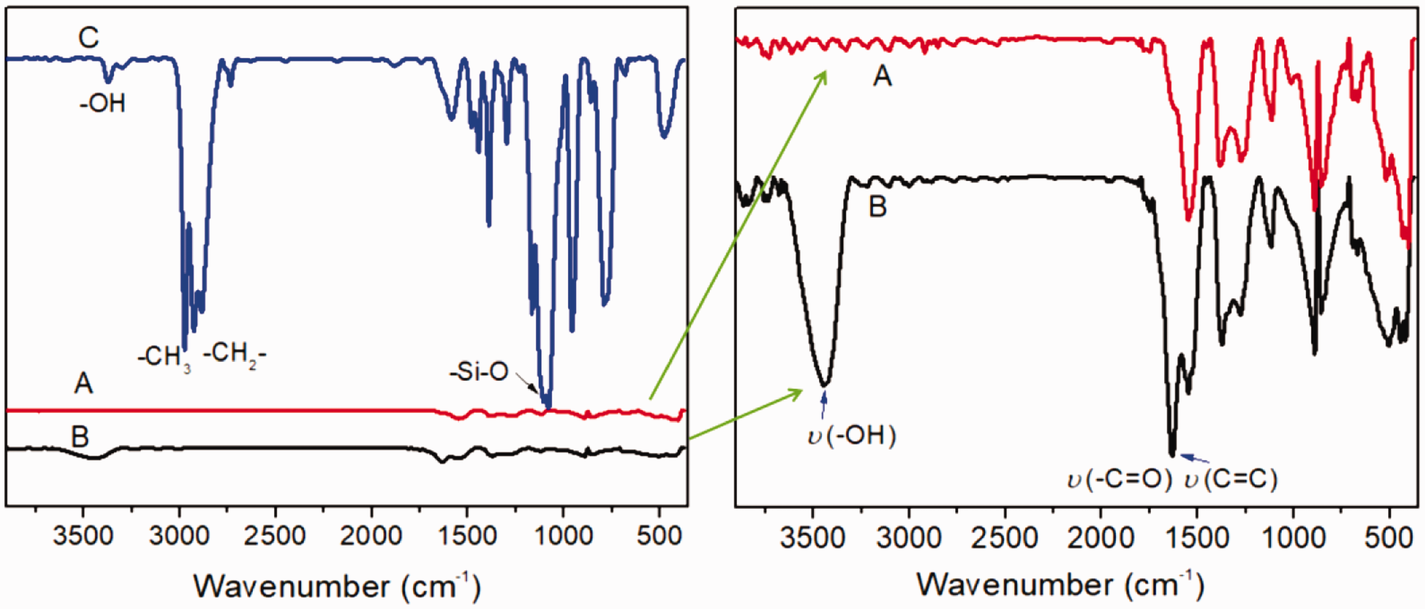
FTIR spectra of untreated and modified carbon fiber (a) untreated CF, (b) modified CF by acid treatment, (c) Carbon fiber treated with acid oxidation and APS.
The mechanical performance analysis of modified CF and composite
Interlaminar shear strength (ILSS) and bending strength are used to quantify the interfacial properties of the CFs and phenolic resin [23]. As seen from the data in Figure 4(a), the ILSS is highly dependent on the surface states of the CF. Specifically, the ILSS of the modified CF/phenolic resin composites is significantly higher than that of the unmodified composite, mainly due to the presence of oxygen-containing functional groups and the roughness of the surface enhancing the mechanical interlock. Figure 4(b) shows the bending stress-strain behavior of composites. A conclusion can be drawn that Cu/CF/phenolic resin contact strip presented typical “false elastic-plasticity effect”. The bond strength of fiber and resin is increased from 127.5 MPa to 170.4 MPa; the fiber can effectively transfer various loads and the impact crack propagation speed is slowed down. At the same time, the flexible group of silane coupling agent promotes the absorption of impact energy. Some untreated fibers are pulled out of the matrix, and the interface combination between CF and matrix is poor, as shown in Figure 4(c). Figure 4(d) shows that the resin and fiber systems are easily integrated. Moreover, the fibers have a purity surface in untreated CF reinforced composite and the fibers (Figure 4(c) and (e)) are coated with resin in modified CF reinforced composite (Figure 4(d) and (f)). Therefore, in the subsequent experiment, the improved CFs is used as the reinforcement of pantograph slider samples, and named as CFRCS.

The mechanical properties of modified carbon fibers reinforced composites: (a) Effect of the modified carbon fiber on ILSS of carbon fibers reinforced composites; (b) The flexural load-displacement curves; (c)-(f) SEM fractography of CFRCS (c and e are untreated CFs as strengthening phases. d and f are modified CFs as strengthening phases.).
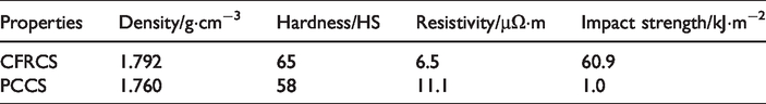
The mechanical properties of PCCS and CFRCS are shown in Table 2. According to the data, the resistivity of CFRCS is about half of that of PCCS, which has the expected benefit of improving current conduction efficiency and reducing arc discharge. The fracture of tribological pairs in electric sliding process will produce arc discharge, which will lead to the increase of wear surface temperature and wear amount [9]. Moreover, impact strength of CFRCS is about 60 times higher than that of PCCS, which means that the breakage rate of contact bands will be reduced.
The mechanical properties of the specimens.
Current carrying friction and wear performance of contact strip
The load quality of the friction pair is an important symbol of power output of electric locomotive [12]. Figure 5(a) shows the relationship between sliding speed (v), wear rate (Ws) and friction coefficient (μ) of CFRCS and PCCS. It can be seen that Ws increased with the increase of v, which contributes to the increase of arc discharge energy. At the same time, the Ws and μ of both kinds of contact strips under the action of current are basically the same. In current, arc erosion is main form of mass loss of sliding electrical contact materials [12,13]. Arc heating increases the wear surface temperature sharply [24], and the resin is oxidized, which deteriorates the contact surface and increases the wear rate. Meanwhile, the wear rate of CFRCS (weight) is about 1.15 times higher than that of PCCS at current density of 100 A/cm2. Thus, the electrical resistance of PCCS is slightly lower than that of CFRCS.

Effect of sliding speed on both wear rate and friction coefficient of CFRCS and PCCS (a) (I = 80 A·cm−2; F = 70 N; t = 30s); the variation of current-carrying efficiency with electrical current (b) and loading (c) for CFRCS and PCCS.
Figure 5(b) and (c) shows how the current-carrying efficiency of CFRCS and PCCS varies with electrical current (I) and loading (F). The test lasted 30 seconds. It could be clearly seen from the figure that with the increase of the load, the current-carrying efficiency presented a relatively stable increasing trend. Conversely, the current-carrying efficiency decreased with the increase of current. Pearson product moment correlation coefficient can be used to quantitatively describe the relationship between arc energy and current-carrying efficiency, as shown in equation (2).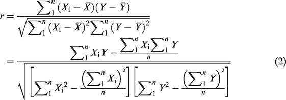
The correlation coefficient of the friction pair energy, the current-carrying efficiency and current-carrying stability were 1, −0.988 and 0.988, respectively. It could be seen that the higher the arc energy was, the lower the current-carrying efficiency, and the worse the load flow stability. For PCCS and CFRCS, the probability of large arc discharge and the arc energy increased with the increase of the sample carrier flow, while the current-carrying efficiency decreased, as shown in Figure 5(b).
The change of wear rate varies of CFRCS with speed was shown in Figure 6(a) under an applied load of 40–90 N, holding for 30 s. The wear rate of CFRCS increased with the increase of rotating speed. However, when the load was about 60–70 N, the wear rate was minimal. Under the action of electric field and friction heat, graphite gasifies and deposits on the friction surface under appropriate pressure to form a dense carbon film, as shown in Figure 6(b). The formation of carbon lubricating film significantly improves the wear resistance of coating.

The wear rate varies with the electric currents (a) and lubricating film forming process on worn surface (b).
Wear mechanism of CFRCS and PCCS against copper
Cross-section SEM micrographs of contact strip specimens were shown in Figure 7(a) and (b). This was the original interface bonding state of composites. It could be seen from the images that the cross-section surfaces were smooth, accompanied by small pores. At the same time, carbon fibers were exposed on the surface of CFRCS. The connection between carbon fiber and resin was good in Figure 7(b). The higher the bond strength between resin and fiber was, the better the mechanical properties of composite. In addition, it is beneficial to the conduction of friction heat and the transfer of internal stress, effectively reducing the wear rate of the contact zone [25]. The ILSS cross-section of phenolic resin contact strip in Figure 7(c) was serrated on the interface between CF and phenolic resin, indicating a high toughness of the interface. When the cross-section is serrated and the toughness of the cross-section is high, the synergistic effect of mechanical and chemical binding force is the largest, and better ILSS strength can be obtained, which is confirmed by the data of Figure 4(a).
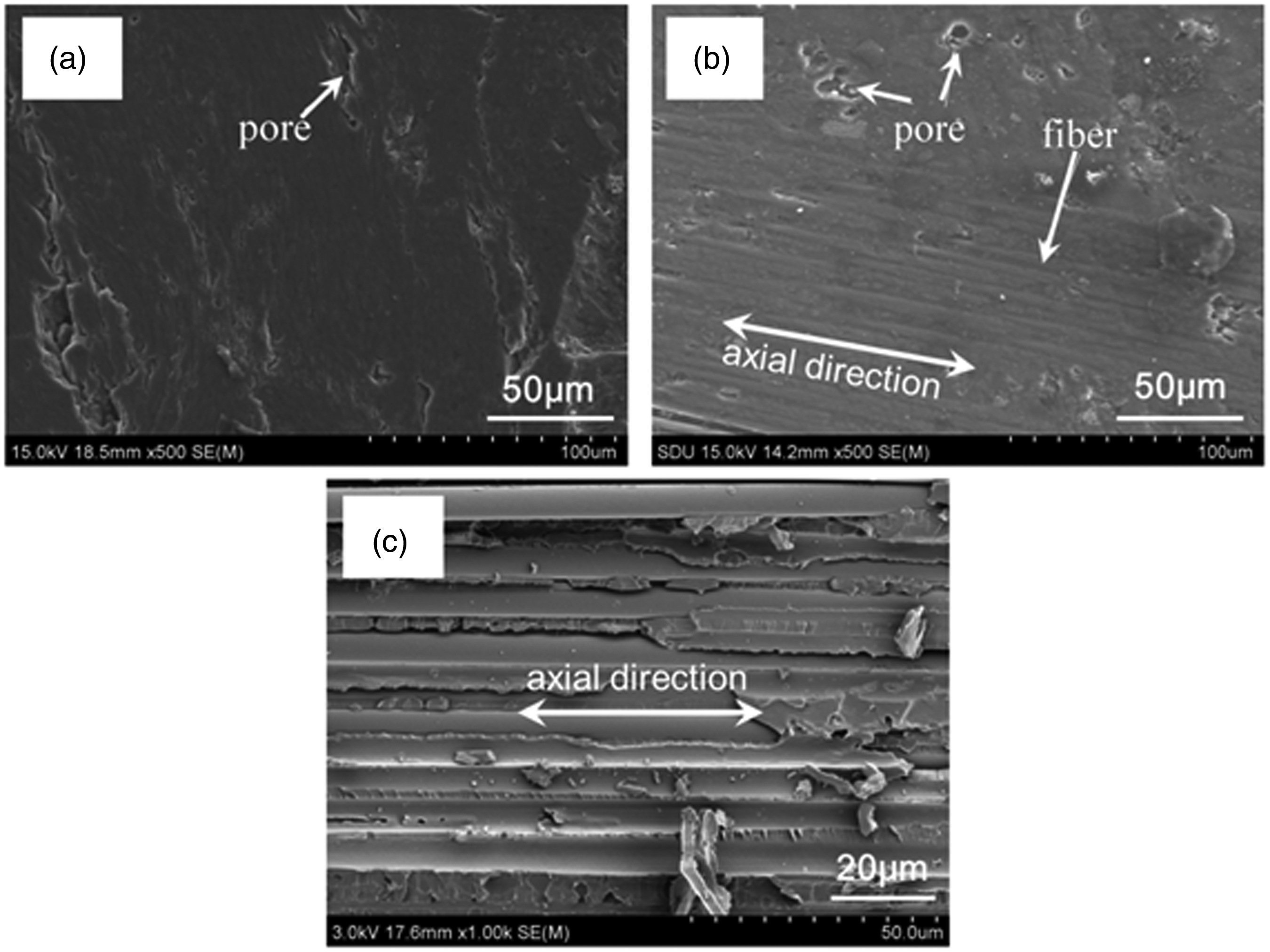
SEM micrographs of different contact strips’ cross-section (a) PCCS; (b) CFRCS and (c) the ILSS cross-section of CFRCS.
The service life of pantograph slide plate depended directly on its wear condition, and its wear quality could represent the wear condition. Therefore, it was necessary to study the degree of friction and wear. Grooves could be found on the wear surface in Figure 8(c), which were the characteristic of an adhesive wear mechanism. Cracks and arc crater on the surface of PCCS resulted in uneven surface and erosion holes (Figure 8(a) and (b)). Besides, the grain-morphology of CFRCS is solid spherical and aggregate. The transient temperature of the worn surface reaches 4000 K due to the arc energy during electric sliding, which leads to corrosion pits and thermal stress cracks [12]. Figure 7(d) shows the erosion pits and thermal stress cracks on the worn surface of CFRCS. The erosion and spalling pits were easily filled with carbon and copper oxide debris. Hence, a continuous film could be also formed on the worn surface (Figure 6). The continuous conductive graphite wear film was conducive to reduce the arc discharge rate and wear rate of CFRCS.
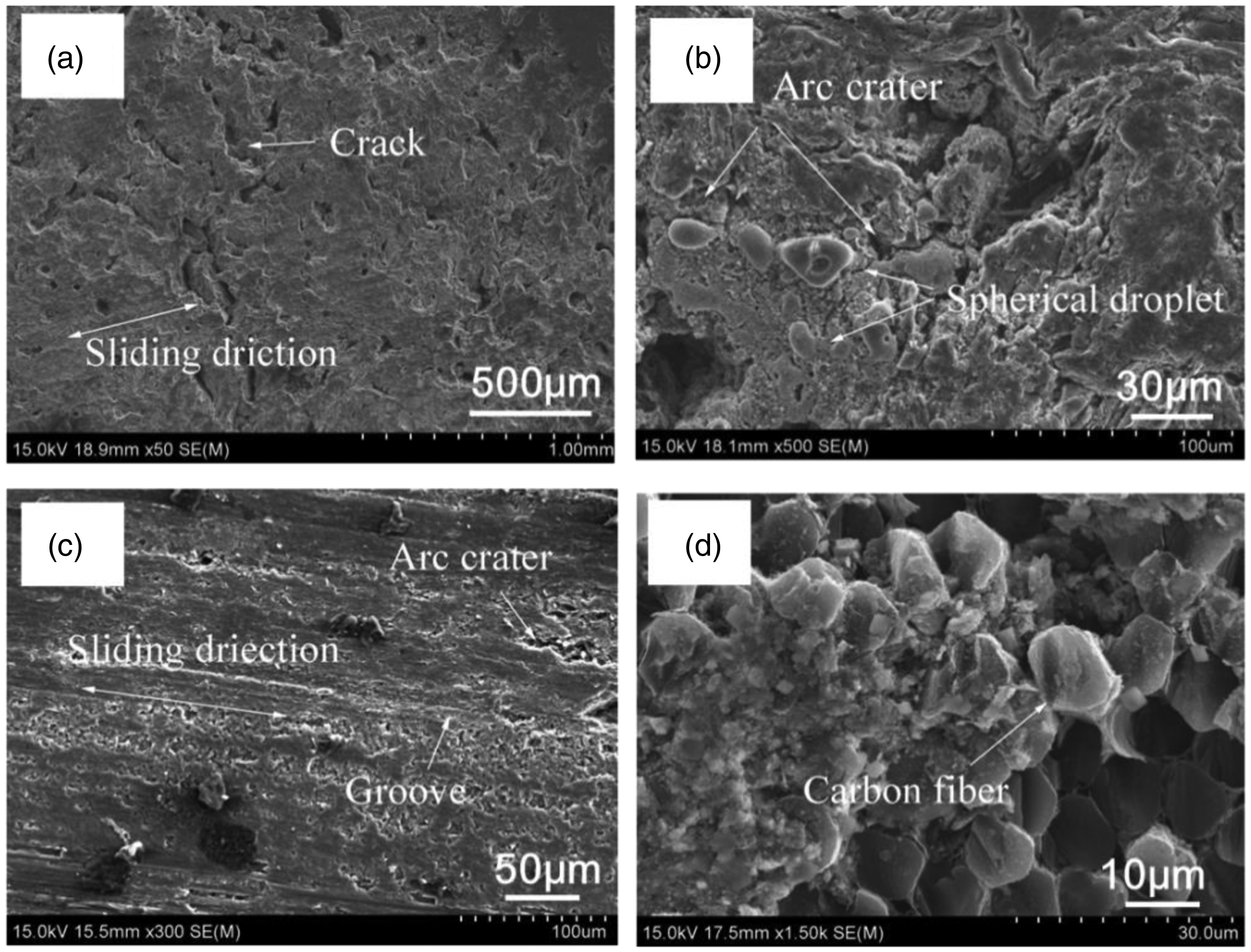
SEM micrographs of worn surface after electrical sliding wear under current of 80 A·cm−2 at speed of 150 km/h (a) (b) PCCS; (c) (d) CFRCS.
Wear surface element data analyzed by EDS were listed in Table 3 (weight percentage). The copper content of CFRCS grinding block was higher than that of PCCS grinding block. The main reason was that the copper content in CFRCS was 17 wt. % and it was transferred from the disk to the contact strip under the friction of the current-carrier. This further confirmed the existence of adhesive wear in the CFRCS-Copper system. In addition, many spherical droplets were observed on the worn surface of PCCS (Figure 8(b)). The spherical droplets formed by arc fusion were about 5–15 μm in diameter under current of 80 A·cm−2. Meanwhile, the oxygen content of worn surface of PCCS was a little higher than that of CFRCS. This was because that arc discharge oxidation was related to the arc erosion. Therefore, the oxidative wear of PCCS was more severe than that of CFRCS.
Elements distribution on worn surface.
The degree of arc discharge at initial stage of friction, the surface of copper wheel after wear and the grinding morphology were also analyzed and discussed to understand the wear mechanisms of friction materials, as shown in Figure 9(a) and (b). The more seriousness of arc discharge was, the more arc erosion wear was. In the friction process, the diversity of components would reduce the number of conducting points, and it was easy to produce arc discharge phenomenon, which might lead to the difference of arc discharge degree between CFRCS and PCCS. Visible carbon film could be seen on the surface of copper disc in the Figure 9(c) and (d). The formation process was shown in Figure 6(b). Under the action of friction heat, Joule heat and arc erosion, phenolic resin in CFRCS is easy to crack and oxidize, and postpones the carbon lubrication film on the friction pair. Therefore, electrical erosion on the surface of CFRCS copper plate was more serious. In Figure 9(e), graphite particles coated with oxidized resin formed flocculation and strip under the action of arc combustion. Copper was melted and solidified on the surface of the abrasive particles by electric arc. In addition, it could be seen from the data in Figure 9(e) and 9(f) that the adhesive wear of the CFRCS-copper disk was more serious than PCCS-copper disk, because the value of Cu in the abrasive particles was much higher.

Comparison on arc discharge degree of CFRCS (a) and PCCS (b) (J = 100 A/cm2, v = 150 km/h, F = 70 N), copper wheel surface pictures after worn with current for CFRCS (c) and PCCS (d) (J = 80 A/cm2, F = 70 N, v = 150 km/h, t = 5 min), grindings topography for CFRCS (e) and PCCS (f) (the value of copper was counted by the difference value between the grindings and formulations) and XRD pattern of wear surface (g).
In the XRD spectrum, the main components on the surface of CFRCS are C, Cu and CuO (Figure 9(g)). The arc heat and Joule heat generated by arc discharge during current-carrying friction raise the surface temperature of the material. Copper on the worn surface is oxidized to copper oxide. Moreover, the XRD peak of copper appears on the PCCS surface after the wear, indicating that the PCCS/copper friction pair has adhesive wear. Copper oxide is virtually absent from PCCS, so the oxidative wear of PCCS is relatively small.
Based on the above analysis, the main wear mechanism of CFRCS and PCCS were given as follows. The current-carrying wear mechanism of CFRCS was mainly arc erosion wear and oxidation wear, accompanied by adhesive wear. However, oxidation wear and arc erosion wear were the main wear mechanism of PCCS.
Conclusions
In this paper, the current-carrying sliding wear behavior and mechanical properties of Cu/CF/phenolic resin contact strip were studied, and the properties of pure carbon contact strip were compared. The following conclusions could be drawn from the test: The surface oxidation treatment of carbon fiber can increase the interfacial properties of composite materials and effectively avoid the interfacial cracking of sandwich materials. The CFRCS had better mechanical properties than PCCS. The impact strength of CFRCS was higher than that of PCCS and the electrical resistivity was lower. The wear behavior of contact strip was mainly determined by current. The electrical wear resistance of PCCS was slightly better than that of CFRCS. With the increase of current, the current-carrying efficiency increases steadily. Conversely, the current-carrying efficiency decreased with the increase of current. The wear rate of CFRCS increases with the increase of velocity. But when the load was 60-70 N, the wear rate was the minimum. Under current-carrying condition, the main wear mechanisms of CFRCS were arc erosion wear, oxidation wear and adhesive wear. Oxidation wear and arc erosion wear were the main wear mechanism of PCCS by analyzing the wear surface and abrasive dust. Carbon fiber reinforced sandwich pantograph sliders with high strength have great potential in high-speed railway.
Footnotes
Declaration of conflicting interests
The author(s) declared no potential conflicts of interest with respect to the research, authorship, and/or publication of this article.
Funding
The author(s) disclosed receipt of the following financial support for the research, authorship, and/or publication of this article:: This work is financially supported by the National Natural Science Foundation of China (52072193, 21404065); the Project of Shandong Province Higher Educational Science and Technology Program [J15LC20, J17KA015]; Shandong Provincial Natural Science Foundation, China [ZR2019BEM018]; the China Postdoctoral Science Foundation [2014M561886, 2015T80695] National College Student innovation and Entrepreneurship Training Program (201911065018, S202011065092) and the Postdoctoral Scientific Research Foundation of Qingdao [2016198].