
Abstract
This work was focused on changes of the compression generated by knitted orthopedic supports during the stress relaxation in order to find in which period of the stress relaxation the most significant part of the compression is lost. The influence of knitted structure, elastomeric inlay-yarn insertion density and shape/orientation of the rigid element fixed on the fabric on the compression and its changes under the stress relaxation was also investigated in this study. 11 different knitted structures and constructions were used in this research. It was found that the higher density of elastomeric inlay-yarn insertion into the knitted structure is not only responsible for higher compression generation, but also makes compression degradation during the time slower. In addition, the higher pre-tension of the elastomeric inlay-yarn leads to the faster relaxation process. Moreover, the shape and orientation of the rigid element can significantly affect the compression generation, however behavior of all variants during the stress relaxation is very similar. Evaluation of the tensile force after at least 120-300 s of the stress relaxation has to be used in design algorithm of very different compression products and applied in estimation of the compression at different manufacturing stages of the product.
Introduction
Knitted materials with elastomeric structure are common and often used for orthopedic compression supports. Knitted compression fabrics are made by knitting together at least two types of yarns, i.e. the ground yarn, which ensures stiffness and thickness of the product, and the elastomeric inlay-yarn, which generates required compression level [1,2]. In order to improve level of generated compression and to achieve better performance of compression support, extra elastomeric inlay-yarns can be inserted into the construction of a knit [2,3]. Elastomeric inlay-yarns can be inlaid, floated or plated into the knitted structure across the width of the fabric or into the selected area. Direction of the inlay-yarn insertion (horizontal, vertical or diagonal) has influence on stability and orientation of the knitted fabric and determines elasticity (or in the case of rigid inlay-yarns - stiffness) of the fabric in the particular [4–7].
Knitted orthopedic supports usually are produced with supplementary details used for different purposes. Orthopedic supports often have added silicone parts for functional application and other rigid components, such as straps, fasteners, etc. [8]. The rigid elements can be classified into three main groups, which are used for: a) medical purposes (elements create the function that is relevant to the patient health and healing process); b) wearing comfort (straps, silicon strips, fasteners, etc., that may affect compression not only according to its relative area, but also due to the different force the consumer uses); c) branding (labels, tags and logos). Supplementary elements for medical purposes are crucial and cannot be eliminated, the relative area of these elements cannot be reduced significantly. Implication of additional elements used for wearing comfort can be questioned and their relative area may be changed. The last group is the branding type elements and the case of this type relevance is negotiable. In the area of low deformations, there is a strong linear dependence between the rigid element relative area and the compression generated by the knitted orthopedic support – compression linearly increases by increasing the area of the rigid element [4]. Rigid elements can significantly affect the compression generated by the support and even change the compression class of the product.
Compression generated by the support depends on the support area, shape and characteristics of a knit, such as knitting pattern, loop density, yarn linear density, etc. Also, there is a high correlation between the mechanical properties of the fabric and its generated pressure [9]. It is known that different geometry of knitted structure generates different mechanical properties, that are strongly related to the fabric structure, yarn properties and direction in which fabric is used [1,10]. Moreover, different knitting pattern may determinate different compression characteristics of the product [11]. The ways how the textile material deforms under applied stresses play an important role on its processing and end-use.
Stress relaxation processes of textile materials are a quite widely investigated area [12–15]. Nevertheless, there is still a lack of research of relaxation process of compression fabrics used for medical application. Orthopedic compression products usually are indicated for long lasting term of wearing and are being worn for the major part of the day. It is already known that compression values of knitted compression products are not equal during exploitation and decrease during the time they are being worn. Alteration of compression during the wearing time may be explained by the stress relaxation process, which appears after putting on or securing product to the body [14,16,17]. However, compression generated by knitted orthopedic supports as well as other knitted compression products is usually estimated at the moment of stretching.
Therefore, the main aim of this study was to investigate tensile force and compression changes during the stress relaxation of compression knitted fabrics with different knitting structure and different shape/orientation of supplementary rigid elements.
Materials and methods
In this study, six variants of knitted structures with different knitting pattern or structure were investigated. Additionally, five variants of specimens with the rigid elements of different geometry were prepared and investigated. Samples of the first pattern type were knitted in the combined laid-in jacquard pattern with elastomeric inlay-yarns inserted into every second course of the knitted structure (this group named as J). Two different values of the pre-tension of elastomeric inlay-yarn (4 cN/tex and 7 cN/tex) were used for the specimens, accordingly named as J_4 and J_7. Samples of the second pattern type were knitted in the plated rib 1x1 pattern and named as R_0/0. Samples of the third pattern type were knitted in the plated rib 1x1 pattern with different inlay-yarn insertion density (into every single, every second and every fourth course), accordingly named as R_1/1, R_1/2 and R_1/4. These knitting patterns were chosen as they are the most popular in knitted compression supports. The main characteristics of the tested knitted fabrics are presented in Table 1. Principal knitting structures of the investigated samples are presented in Figures 1 and 2. The experimental samples were knitted on a 14E gauge double needle-bed flat knitting machine CMS 340TC-L (f. STOLL, Germany).
Main characteristics of the knitted samples.
Note: PA – polyamide, PU -polyurethane.

Investigated combined laid-in jacquard pattern with elastomeric inlay-yarns: a) technical-face side; b) technical-back side; c) principle knitting pattern.

Investigated plated rib 1x1 pattern (a) and principle knitting structure with inlay-yarn inserted into every fourth course R_1/4 (b); every second course R_1/2 (c); every single course R_1/1 (d); without inlay-yarn R_0/0 (e).
Samples of the third pattern type were prepared by adding the rigid element to the structure of the knit. The first type of the knitted pattern (combined laid-in jacquard pattern with 4 cN/tex pre-tension of the elastomeric inlay-yarns in the yarn feeder) was used as the ground material. Five rigid elements with their different geometrical shape (circle, square and three types of rectangular) were fixed to the center of the knitted sample. The relative area of the sample covered by all rigid elements was the same – 18%, however, all these elements differ from each other in width and height. Parameters of the samples with rigid elements are presented in Table 2 and principal structures of these samples are presented in Figure 3.
Main characteristics of the knitted samples with rigid elements.


Principal view of investigated samples with rigid elements.
The stress relaxation process was observed using universal testing machine ZWICK/Z005 according to Standard EN ISO 13934-1:2000. The tensile speed was 100 mm/min, distance between clamps 10 cm, pretension 2 N, sensor 5 kN. Samples were strained up to the 20% and 30% fixed elongation and held in this position for selected period. Such elongation values were chosen as the most reached in knitted orthopedic compression supports. The objects and regimes of stress relaxation are presented in Table 3. The stress was recorded as a function of the time. Complete equipment for research and stretching machine was operated by the testXpert® software. Average values of five elementary tests were presented in this work. The coefficient of variation did not exceed 3%.
Regimes and objects of stress relaxation tests.

Compression of the tested samples was calculated by the Laplace formula:
All experiments were carried out in a standard atmosphere for testing according to Standard LST EN ISO 139:2005.
Results and discussions
The main purpose of compression products usage is the need of compression therapy. The only way to generate compression for the textile product is being stretched before set to the body part. Different methods are used for assessment of the compression and most of them are based on the value of compression generated during the product stretching, regardless of possible compression changes during wearing. Nevertheless, after securing knitted compression product to the body, stress relaxation appears in the knitted structure. In the previous researches [14,15], it was scientifically proved that the compression generated by the support significantly decreases during the wearing due to the stress relaxation process.
In order to estimate the interval of the stress relaxation in which drop of the tensile force as well as of the compression is the fastest, long-term relaxation test was performed for samples of the group J. The samples were stretched up to 30% fixed elongation and held in this position for 2,00,000 s stress relaxation period. Changes in the tensile force and compression during the stress relaxation process are presented in Table 4.
Changes of tensile force and generated compression during long-term stress relaxation.

It was found that the main alterations (up to 57%) appear during the first 500 s of the stress relaxation process; it was also proved in previous investigations [14]. According to the obtained results, the loss in the tensile force from 26.72% to 42.81% was observed during the first 100 s and almost half (47.15 – 57.31%) of the total tensile force was lost during the first 200-500 s, depending on the sample group. Such behavior during the long-term stress relaxation was also found by other researchers; it was found that the main changes in the stress relaxation of various types of yarns occur during the first 200 s [17]. It was observed that for the samples J_7 with the higher elastomeric inlay-yarn initial pre-tension in a yarn feeder during the knitting (7 cN/tex), it is characteristic much higher compression loss during the long-term (2,00,000 s) stress relaxation process (31.5%) compared with the samples J_4 knitted with the lower (4 cN/tex) elastomeric inlay-yarn pre-tension, only 17% for the latter. It leads to the fact that the influence of the elastomeric inlay-yarn pre-tension in a yarn feeder on the tensile force as well as on the compression generation gradually decreases during the time. At the initial point of relaxation, tensile force values of these samples differed in 17%, however, after 2,00,000 s stress relaxation the tensile force values of both variants were very similar. It is because of the inner changes in the elastomeric yarns during the long period of the stress relaxation and it is based on the stress relaxation theory [17].
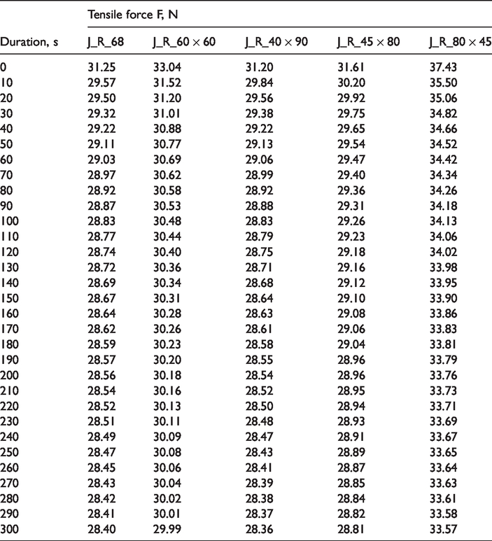
Thus, it is clear that short-term relaxation is the subject for improved compression assessment. According to the results of performed long-term stress relaxation process, the 300 s duration of the short-term stress relaxation was chosen. In the case of short-term stress relaxation, all groups of the J and R type samples were tested and tensile force values were noted after every 10 seconds. Results of the tensile force alteration of the J and R groups samples during the short-term (300 s) stress relaxation process are given in Table 5. The samples were stretched up to 30% fixed elongation and held in this position for selected stress relaxation period. Coefficient of variation of the experimental data was up to 2.17%. The total decrease of the tensile force during the short-term stress relaxation was 9.0%–11.8% for the samples of the J group, and 10.0%–13.6% for the samples of the R group.
Tensile force changes during short-term stress relaxation.

The percentage alterations of the compression of the J and R group samples during the first 300 s of the stress relaxation are presented in Figure 4. This process has no linear character and can be very well described by logarithmic equations (the coefficient of determination R2 in all cases varied between 0.9818 and 0.9987).

Percentage alteration of compression during stress relaxation: (a) J_4 and J_7 samples, (b) R_0/0, R_1/4, R_1/2 and R_1/1 samples.
Results, presented in Figure 4, confirmed that fabrics knitted with higher inlay-yarn pre-tension (J_7) undergo higher compression loss even during the short-term stress relaxation [15]. This is because of the inner molecular-level changes in the elastomeric inlay-yarn PU core during the short-term stress relaxation [17] since compression generation depends mostly on elastomeric inlay-yarns. Moreover, behavior of compression fabrics knitted with different insertion density of the inlay-yarn into the knitted structure during the 300 s stress relaxation highlighted differences not only in the level of compression generation, but also in the rate of compression changes during the time. Despite the different compression generated at the time of stretching, percentage compression alteration of the fabrics R_0/0 (without additionally laid elastomeric inlay-yarn) and R_1/4 (with elastomeric inlay-yarn laid in every fourth course, i.e. with low density) is very similar during the whole period of observation (300 s). It means that the low density of the elastomeric inlay-yarn laying does not have significant influence on the stress relaxation as well as on compression changes compared to the original knitted structure without the inlay-yarns. The low insertion density of the inlay-yarn cannot significantly change behavior of the specimen as stitches in the knitted structure play significant role in the stress relaxation process. Different situation is presented by fabrics with higher elastomeric yarn insertion density, i.e. with the inlay-yarn inserted in every second course (R_1/2) and in each course (R_1/1) of the fabric. Behavior of these specimens mostly depends on processes caused by the stress relaxation in the inner PU core of the elastomeric inlay-yarns. In this case, compression alteration is clearly slower. It is very important that high insertion density of the elastomeric inlay-yarn is not only responsible for the higher compression generation [1], but also impedes compression degradation during the time. This is very important for the successful healing process by wearing compression orthopedic supports.
Compression orthopedic supports often contain various rigid elements. Rigid elements may be used for medical reasons or to ensure correct fastening of the product to the body parts or even for branding [15]. Regardless of the rigid element function, all rigid elements may change elasticity and generated compression of the entire product as they change stretchable area of the compression support. As it was found in previous investigations, effect of the rigid element on compression generations appears when the relative area of a compression support covered by the rigid element is more than 3% [8]. However, the previous investigations were focused only on the area which is covered by rigid elements [8] but did not analyzed the shape and orientation of the element. Usually rigid elements have circular or rectangular shape. In order to investigate influence of the shape and orientation of the rigid element on the compression and its alteration during the stress relaxation process, samples of the group J_R were tested. It is already known that compression generation depends on the size of the rigid element [8], i.e. on the relative area of the compression support covered by the rigid element. However, it is not clear if a different shape of the rigid element can have an influence on compression generation. In this research, the same relative area of the rigid element (area of the specimen covered by the rigid element) but different shape of it was used to investigate if the shape of the rigid element and orientation of it on the compression support has influence on the tensile characteristics of the specimens. Specimens of the group J_R were stretched in the course direction up to 20% fixed elongation and held in this position for selected relaxation period (300 s). Coefficient of variation of the experimental data was 0.18–2.09%. Obtained results of the tensile force are presented in Table 6.
Tensile force changes during short-term stress relaxation (group J_R).
According to the obtained data, it was found that the shape of the rigid element and its orientation on the support affects the tensile force as well as generated compression even up to 20% (see in the Figure 5), despite the same relative area of the rigid element.
Correlation between compression and shape/orientation of the rigid element.
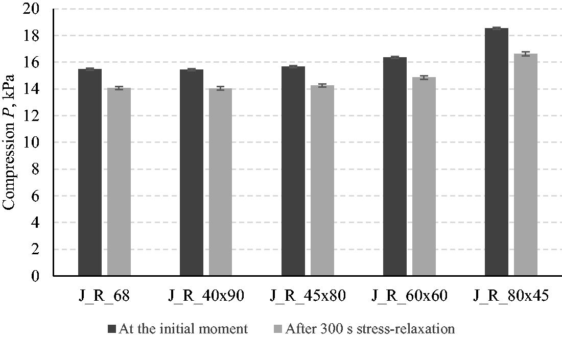
Relative errors of all tested samples did not exceed 2% (the relative error bars are presented in Figure 5), while differences between results of knits with circular rigid element ant with rectangular rigid element in some cases were higher. Relative errors between compression values of the samples J_R_68 and J_R_40 × 90 as well as between the J_R_68 and J_R_45 × 80 also did not exceed 2%; and it means that all mentioned differences are in the limits of errors and are insignificant. Differences between values of the J_R_68 and J_R_60 × 60 and between the J_R_68 and J_R_80 × 45 were 5–6% and 18–20% respectively, which means that the differences are statistically significant in comparison with related errors of each sample tests.
Number of courses (the height of the element) occupied by the rigid element has the main influence on compression generation. It is obvious that the higher is the number of courses, occupied by the rigid element, the higher influence it has on the compression generation. 50% increase of the rigid element height causes 6–13% increase of the tensile force at the initial stretch moment and 5.8–12% after 300 s stress relaxation. While 100% increase of the height causes 20% higher tensile force at the initial stretch moment and 18.4% after 300 s stress relaxation. There are two important moments. First of all, it is evident that influence of the rigid element geometry decreases during the time. Additionally, the influence of the rigid element on the compression generation increases by increasing the percentage height of the compression support occupied by the rigid element. The difference between the compression values of the specimens J_R_40 × 90 and J_R_60 × 60 is not so big as between the specimens J_R_60 × 60 and J_R_80 × 45. This is due to significantly reduced stretchable area of the sample. It can be concluded that when the height of the rigid element is more than 30% of the total height of the support (in our case the height of the specimen was 200 mm), the influence of changes in the rigid element height on the compression changes become substantial. Moreover, the shape (circular or rectangular) of the rigid element also can have significant influence on the tensile force, as it can be seen in Figure 5. The total height (i.e. the diameter) of the rigid element on the specimen J_R_68 is higher than of the element on the specimen J_R_60 × 60, however, compression generated by the specimen J_R_60 × 60 is higher. This is due to the different distribution of the courses/wales occupied by the rigid element. If only few wales are occupied by the rigid element (at the top and bottom of the circular element), it does not have big influence on the stretchability of the knitted sample.
The compression alteration of the J_R group samples during the short-term (300 s) relaxation is presented in Figure 6. It was observed that even 57.75–61.40% of the total tensile force loss of the samples with rigid elements occurs during the first 20 s of the relaxation process, and even 83.45–85.49% of the total tensile force is lost during the first 100 s, depending on the sample group. This experiment confirmed that influence of the stress relaxation on the compression generation is similar for very different knitted compression structures and construction. The main compression changes appear during the first 100-300 s.
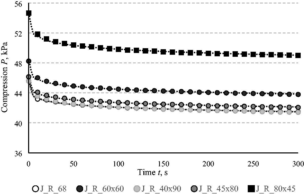
Compression alteration during short-term (300 s) stress relaxation (J_R group with rigid elements).
It was already proposed to evaluate compression generated by the finite compression orthopedic support after at least 120 s after extension in specific wearing conditions (i.e. after the short-term stress relaxation) [15]. With the reference to the data from experimental research, the evaluation of the tensile force during the 120-300 s of the stress relaxation is suitable for both finished products and elements of the product, irrespective of their knitting pattern, structure or construction.
Conclusion
This research confirmed that behavior of the knitted compression material during the stress relaxation process remains similar for different knitted structures and construction of the knitted orthopedic support. Tensile force values and compression consistently decrease during the stress relaxation. It was found that influence of the elastomeric inlay-yarn initial pre-tension in a yarn feeder to the tensile force gradually sinks during the stress relaxation process. At the initial point, compression of the samples knitted with 7 cN and 4 cN pretension differed by 17%, however, after 2,00,000 s stress relaxation compression generated by these samples was very similar. The higher pre-tension of the elastomeric inlay-yarn leads to the faster relaxation process. Additionally, the higher inlay-yarn insertion density determines lower relative compression loss during the stress relaxation. It is very important that the higher insertion density of the elastomeric inlay-yarn is responsible not only for the higher compression generation, but also impedes compression degradation during the time. Also, it was found that the shape (circular or rectangular) and orientation of the rigid element can significantly affect the compression generation (in the investigated case, up to 20%), as a number of courses occupied by the rigid element has the main influence on compression generation. However, this influence slowly decreases during the time.
Investigated results of the long-term and short-term stress relaxation of different structure and construction samples showed that the main decrease of the tensile force was found during the first 120-300 s of the stress relaxation, compared with the total decrease of the tensile force during the long-term (2,00,000 s) relaxation. Thus, the proposed methodology to evaluate tensile force changes during not less than 120-300 s of the stress relaxation has to be used in design algorithm of very different compression products and can be applied to evaluate compression at different manufacturing stages of the product.
Footnotes
Declaration of conflicting interests
The author(s) declared no potential conflicts of interest with respect to the research, authorship, and/or publication of this article.
Funding
The author(s) received no financial support for the research, authorship, and/or publication of this article.