
Abstract
The high demand for quality in the manufacture of absorbent hygiene products requires the adhesive bonds between layers to be as uniform as possible. An experimental study was conducted on two industrial multihole melt blowing nozzle designs used for hot-melt adhesive applications for hygiene products, in order to study two defects that influence the quality of the adhesive bond: fibre breakup, resulting in contamination, and the presence of shots, undesirable lumps that end up in the finished product. To this end, the fibre dynamics were captured at the nozzle exit region by using high-speed imaging. From the results it was observed that die drool is the main source of shot formation, while fibre breakup occurs as a result of applying a sufficiently large force in the direction perpendicular to the fibre. In addition, three dimensionless parameters were defined, the first two being the air-polymer flux ratio and the dimensionless temperature ratio, both of which represent the operating conditions, and the remaining one being the force ratio, which represents the nozzle geometry. The effect of these parameters on fibre breakup and shot formation was studied and the results indicate that both the operating conditions and the nozzle geometry were responsible for the onset of the fibre breakup and for the formation of shots. More precisely, both defects turned out to be dominated by the air-polymer flux ratio and the air tilt angle. The results that emerge from this study are useful for the enhancement of industrial melt blowing nozzles.
Introduction
In the melt blowing (MB) process, a polymer stream is molten and extruded through a set of nozzles and it is immediately blown and attenuated by a set of convergent high-velocity hot-air jets. Among all the industrial processes available for producing nonwoven microfibers, the MB process is particularly effective because it allows webs with a high surface area per unit volume to be produced, usually without requiring any finishing operations [1]. More recently, the MB process has begun to be used to produce hot-melt adhesives, which are used in various industrial processes to bond different kinds of products, such as products that include nonwoven fabrics. Particularly, in melt blowing adhesives, the final fibre diameters range from 10 to 20 µm [2]. The MB system comprises a MB head that supports a set of nozzles, which can have different designs [3], depending primarily on the desired characteristics of the application pattern. A scheme representing the principal components in the melt blowing process is shown in Figure 1. However, because each nozzle design leads to different defects on the produced application pattern, the aim of this article is to study two MB nozzle designs and explain how the geometric and operational factors of each design lead to their respective defects on the adhesive patterns. Depending on production requirements, the fibres can be extruded either continuously or discontinuously, but in the present work only the continuous extrusion of polymer by non–contact nozzle designs are studied. Non-contact nozzles present some advantages when compared with contact nozzles, for example they present a better clog resistance and permit bonding uneven surfaces. They are also better for bonding temperature sensitive materials.

Sketch of the melt blowing process.
Two aspects of the MB process are not yet fully understood, namely the fibre breakup process and shot formation (or drop formation). The first is a key subject because fibre breakup reduces the fibre’s mean diameter, thus increasing the fibre’s surface area and the uniformity of the adhesive bond. However, excessive fibre breakup causes undesirable defects, such as flies. To date, little information has been published about the factors that lead to fibre breakup in the MB process. C. Ellison et al. [4] observed that, for viscoelastic fluids, fibre breakup depends on the polymer’s melt viscosity and elasticity, which control the extensional stress, the operating temperature and the air-polymer flux ratio. An increase either in the temperature or in the air-polymer flow ratio increases the fibre breakup. Moreover, they associated the onset of this phenomenon with the presence of spherical particles dispersed amongst the fibres. Y. Wang et al. [5] conducted uniaxial stretching experiments on styrene-butadiene rubbers to study fibre breakup of polymer melts. The authors reported that the yield extensional strain
Regarding shot formation, it is known that in hot-melt adhesive applications this is a matter of special importance because the presence of shots in the application pattern reduces the uniformity of the adhesive bond and therefore the quality of the final product, as well as increases the amount of adhesive wasted unnecessarily. Shots are also undesirable because they can cause heat distortion if the material is temperature sensitive. The formation of shots is primarily attributed to operating conditions and equipment cleanliness. For instance, R. Breese and Z. Yan devoted two articles to the study of the shot phenomenon [8,9]. In the first one, they studied how the number of shots vary as a function of the die-to-collector distance (DCD) and the web basis weight, and they explained the shot formation process on the basis of three different models: the fibre transformation model, the direct shot formation model and the shot precursor model. However, they concluded that no model alone could explain all the experimental observations and stated that shot formation probably involves all three mechanisms. In the present study, only the direct shot formation model is considered in order to explain the formation of shots. In the same article, Breese and Yan also stated that the shot particle’s diameters are in the range 100–300 µm, a noticeably larger size than the average fibre diameter. In their second article, Breese and Yan presented a computer software tool they developed to analyse MB web images automatically and calculate several characteristics of the shot, such as: the number of shots, the size-distribution, the mean size and the cover rate. What is more, R. Shambaugh describes the fibre shots as undesirable lumps that are larger than 300 µm in diameter while stating that the shots typically form under certain operating conditions [10]. Other authors have affirmed that shot formation is a consequence of the fibre breakup and explained that shot formation is connected to the fibre elastic snap back effect and to the fusion of filaments on the way to the collector screen. In view of this, it can be stated that there is no universal agreement among researchers on the sources of shot formation, and in the present work an additional explanation is given.
The aim of this article is to extend the present knowledge of these two defects by clarifying how the nozzle geometry and the operating conditions of multihole MB nozzle designs can affect both fibre breakup and shot formation. Regarding the first phenomenon, the results obtained in the present work suggest that fibre breakup is affected by both the operating conditions and the nozzle geometry. Achieving fibre breakup conditions would require working with high air and low polymer flow rates and with high polymer temperatures, while using a nozzle design with highly tilted air ducts. Regarding the second phenomenon, the findings suggest that shots form as a result of the accumulation of adhesive at the nozzle tip (die drool), and working at low polymer temperatures and air flow rates and with high polymer flow rates will help to minimize the formation of shots. The present work also demonstrates a lower formation of shots in nozzle designs with highly tilted air ducts.
Experimental
Description of the nozzle geometry
Since the multihole (or laminated) nozzle geometry ensures consistent bonding between adjacent layers and the application pattern produced by contiguous nozzles does not overlap, it is popular among the MB nozzle designs when it comes to the disposal of hot melt in hygiene products. In the present study, two multihole melt blown nozzle designs used to apply hot-melt adhesive to hygiene products intended to absorb bodily fluids were studied, and both designs are industrial prototypes, which were designed based on two existing commercial designs. Laminated melt blown nozzles consists of an assembly of several metallic plates, where the air orifices and the adhesive capillaries lie. The set of plates is screwed to the body of the nozzle. From now on, the two nozzle designs will be named as A Design and B Design respectively. Both nozzle designs were studied on a modular MB head with interchangeable modular units placed side by side. The melt blown head used for the experiments support 5 modules, each holding a nozzle with a given number of polymer exits, with each exit being surrounded by a certain number of air exits
In the multihole nozzle designs, the air exits are often non-parallel to the adhesive exits, hence an angle forms between them. The tilt angles between the air exits and the adhesive capillary in the

Dimensions and parameters defining the nozzle designs: (a) A design and (b) B design. Photos of the nozzles dispensing adhesive (c) A design and (d) B design.
For convenience, a unique parameter that indicates the angle between the air ducts and the polymer capillaries will be defined as a function of the previously defined angles


Representation of one quarter of a general multihole nozzle.
Where
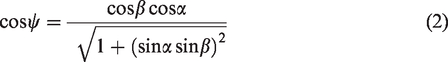
From equation (2), it can be verified that if
In addition to the global tilt angle (
Polymer characterization
Hot melt adhesives are mainly composed of a high molecular copolymer, resin and wax [11]. This type of adhesive is commonly solid at ambient temperature, becomes tacky as it is molten and forms a strong adhesive bond as it cools. The adhesive used in the present study is a typical commercial construction polymer (whose commercial name is PM357V) used in the manufacturing of hygiene products, such as diapers and sanitary napkins. The adhesive has been manufactured by company Savaré. More precisely, this is a styrene butadiene styrene (SBS) based adhesive, whose formula includes other components such as hydrocarbon resins, oil minerals and less than 3% in other additives. Based on thermoplastic rubber, its viscosity is 1.6 and 7.3 Pa.s at 170°C and 130°C, respectively, presenting a similar thermal behaviour to other hot-melt adhesives used for sanitary applications [12]. Its softening point is about 76°C (ASTM E 28, water), its flash point is over 200°C and its maximum running temperature is 170°C, which establishes the maximum value for the polymer operation temperature on the experiments.
Figure 4 shows the shear viscosity curve of the adhesive, which is given by the Cross Model, from which

Adhesive’s viscosity as the function of the shear rate at
Experimental facility and recording parameters
Given the fast fibre dynamics present in the melt blowing of hot-melt adhesives, a high-speed camera must be used to capture the fibre shot and the fibre breakup in the nozzle exit region. Figure 5 shows an image and a sketch of the experimental setup that was used for this commitment. The experimental facility comprises the MB head with the set of nozzles, supported by a 3-degree-of-freedom manual positioning mechanism, the high-speed camera (Photron FASTCAM Mini AX200) and a cold light source (Tungsten Light Head COOLH dedocool). In order to record the images under backlight conditions, the camera was placed facing the light source. To adequately focus on the fibre, the camera was mounted on a micrometric platform, which allowed very precise positioning along the

Experimental facility used for the high-speed imaging: (a) photograph and (b) sketch.
After conducting preliminary tests, the appropriate number of frames per second (fps) required for capturing the fibre dynamics turned out to be 14,400 and 19,200 for the A and B designs, respectively. The resulting FOV for each case comprised 384 × 1024 and 256 × 1024 pix2, which translated into 3.3 × 8.7 and 2.2 × 8.7 mm2, respectively. A total of 950 frames where recorded in each experiment, which is equivalent to about 65 and 50 ms of recording time for the A and B designs, respectively. The shutter speed was set to 1 µm, which resulted in a proper exposure time that permitted the recording of bright and sharp images, with no blur.
Operating conditions
Three are the operating factors that are usually considered when studying the MB process: the air flow rate polymer temperature between 138 and 163 degrees Celsius. polymer mass flow rate is between 0.1 and 10 g/min/hole. air flow rate between 2.8 and 56.6 L/min/inch.
Table 1 presents the experimental conditions that were set for all the experiments conducted, which vary within the typical range of variation presented above. All these conditions were taken from real industrial hot-melt adhesive applications for hygiene products. The air temperature
Operating conditions established for performing the HSI.
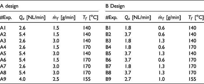
The polymer mass flow rate and temperature were controlled from the MB control system. The adhesive was heated while stored inside the MB tank and also inside the MB head. The adhesive pump provided a volume of 2.5 cubic centimetres of adhesive per each revolution. The precision of the adhesive heating system is about ±0.5°C, as indicated by the manufacturer. At the same time, the airflow rate was controlled with a pressure regulating valve followed by a flow meter with a precision of ∓ (3% o.m.v + 0.3% of the full scale -600 NL/min-), and in the conducted experiments it represented 4 to 6% of the flowrate. The air temperature was controlled from the MB control system, where the air was heated only at the nozzle head, before reaching the nozzles. Before each recording was done, the system was allowed enough time to reach steady state conditions. As is regularly done in continuous hot-melt applications, the polymer mass flow rate and the airflow were both kept constant during the experiments.
In what follows, some dimensionless operating parameters will be defined in order to express the operating conditions of Table 1 in a more compact way. First, a number that represents the ratio between the air and the polymer flow rates will be defined as:
This number will be called the air-polymer flux ratio, and it has been used in the past by other authors to study how the operating parameters affect the MB process [10,13]. On the one hand, the quantities that appear on the numerator of equation (3) are the air density at normal conditions (
This number is referred to as the dimensionless temperature ratio. This dimensionless parameter is similar to the polymer-air temperature ratio defined by R. Shambaugh [10], but it also includes the ambient temperature 
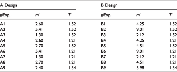
Table 2 shows the experimental conditions for the experiments in Table 1 in non-dimensional form.
Operating conditions established for the HSI expressed in dimensionless terms.
Procedure for measuring the fibre diameter at the nozzle exit region
The formation of shots will be calculated in terms of the coefficient of variation of the fibre diameter at the nozzle exit region. Given the positive results obtained by other researchers when performing automated fibre diameter measurements in melt-blown webs using image processing techniques [14], a tailored MATLAB program was used to measure the fibre diameter. To this end, the image contrast was first adjusted and then it was converted from grayscale into binary format by setting an adequate conversion level. Then, the program split the image into 16 horizontal segments and proceeded to locate the row number (in pixels) of the first row on each of these segments. Then it went through all the pixels of each row and located the first and the last black pixels, which corresponded to the endpoints of the adhesive fibre. Finally, the last step of the measurement procedure of the fibre diameter comprised the subtraction between the pixel column number of these two border-pixels and the subsequent conversion from pixels to millimetres by means of a calibration factor. In order to determine the latter, a millimetre ruler was placed horizontally as a temporary target inside the camera’s FOV, and by using the high-speed cameras software the calibration factor was determined as the number of pixels that correspond to eight millimetres in the ruler. Considerations were also taken on the distortion on the fibre diameter measurement due to bending effects, by multiplying the measurement by a correction factor which depends on the angle that forms the fibre centreline with the horizontal axis. The calculations that lead to the bending correction factor can be found in the Supplemental Material. Figure 6 depicts the procedure followed for measuring the fibre diameter. After measuring the fibre diameter at numerous points below the nozzle exit, the most adequate location for calculating the coefficient of variation had to be selected. In the recorded videos, it was observed that the shots form right at the polymer exit before descending. However, the measurements had to be taken far away enough from the nozzle exit, in a location where the fibre diameter stays constant until it reaches the collector screen. The point along the

Sketch illustrating the measurement procedure of the fibre diameter at the nozzle exit region.
No measurements were performed in cases in which either fibre breakup occurred (experiments B2, B4, B5, B6, B8, B9) or the presence of loops did not allow for precise measurement of the fibre diameter (experiment B7). The results obtained by performing one repetition per each experiment turned out to tally well with the results from the primary experiments, the difference in the fibre diameter at
The uncertainty in the fibre diameter measurements was calculated based on three main components: the uncertainty in the image conversion factor in going from grayscale to binary format, the uncertainty in the calibration factor and the uncertainty due to the variation in time. The uncertainty was calculated following the procedure suggested by R. Moffat [15] and was estimated to be about 11 and 9 µm in the A and B designs, respectively. Details concerning the uncertainty calculations can be found in the Supplemental Material.
Momentum balance
A momentum balance is determined on an adhesive fibre in order to find out how the geometric parameters of the nozzle affect the horizontal and vertical components of the air force exerted on it, which will be ultimately useful for explaining the cohesive fracture of the fibre. The analysis will focus in a set of exits of the nozzle, that is, one polymer exit with its surrounding air exits. For convenience, it is assumed that each air exit has an identical counterpart opposite to the fibre exit. Consider the control volume (CV) shown in Figure 7, with its inner surface delimited by the polymer fibre, its upper surface delimited by the nozzle exit and the side surface defined as the stream surface that delimits all the air jets that correspond to a single polymer exit
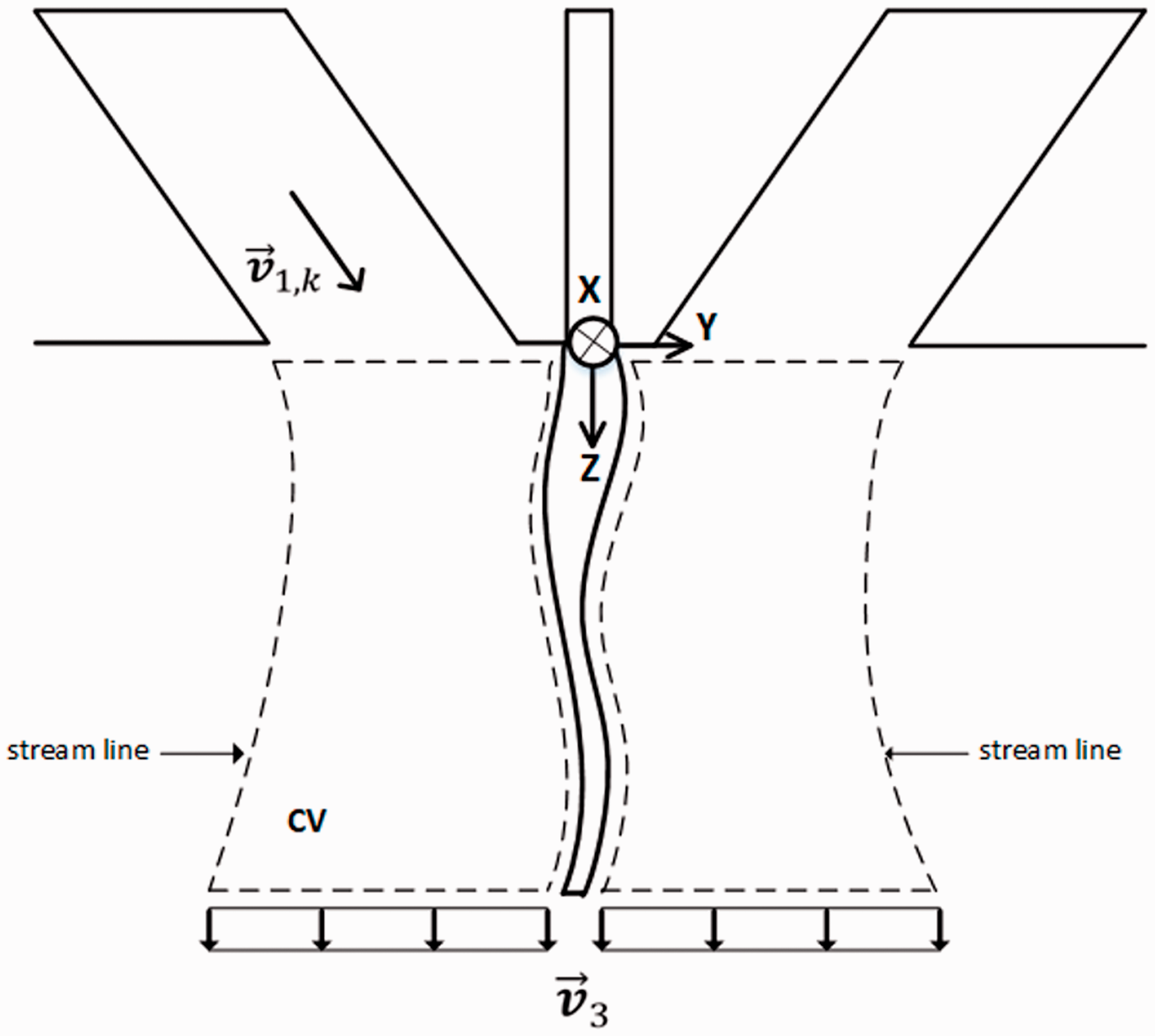
Control volume chosen for analyzing how the momentum is transferred from the air jets to the polymer fibre.
The quotient between the horizontal (along 


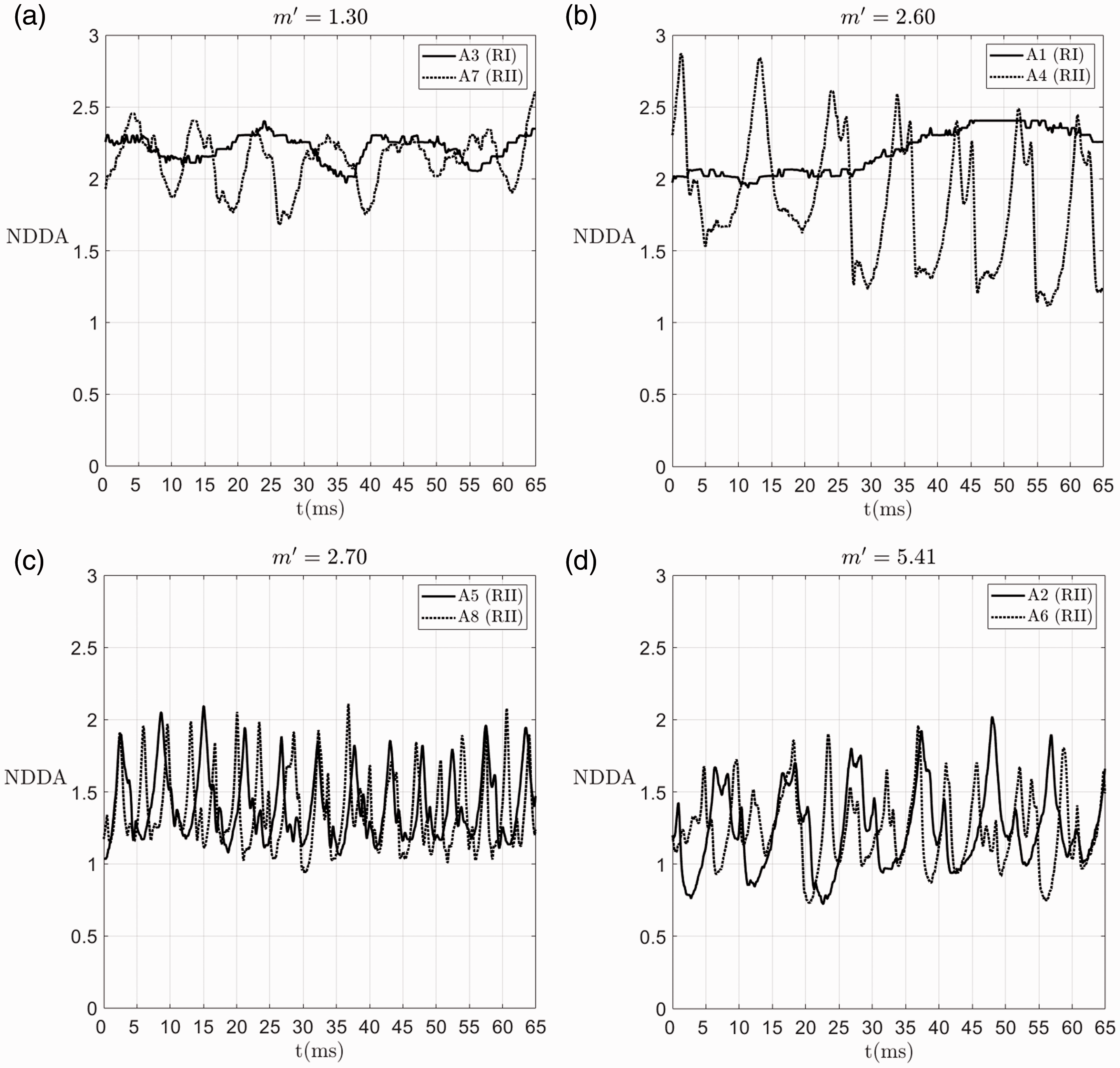
The force ratio for an annular nozzle design can be calculated by following a similar procedure, which is also detailed in the Supplemental Material, resulting in equation (9):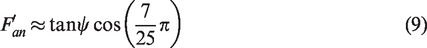
Results and discussion
Fibre dynamics
The fibre dynamics were recorded at the nozzle exit region in both nozzle designs using HSI. The fibre exhibited a different dynamical response to the airflow field in each of the two nozzle designs.
In previous work on the classification of the polymer fibre response in different operating conditions, R. Shambaugh differentiated three different regions of melt blown operation [10]. Region I (RI) represents the low gas velocity region where the fibre has little or no oscillating motion and the fibre stays nearly parallel to the air stream, below the air impinging point. If the airflow is increased, the fibre enters Region II (RII), where some adhesive lumps, commonly known as shots, form along the fibre thread. Finally, if the air flow rate continues to increase, the shots are attenuated, and the resulting melt blown fibre is very fine, which represents Region III (RIII). The present results not only confirm the existence of these three regions but also introduce some additional ones that arise from the transition between some regions. The same naming convention introduced by Shambaugh will be used in this work.
In what follows and based on the high-speed camera recordings, we describe the transition that the fibre experiences as the operating conditions vary (only for the operating range presented in Table 1), maintaining and expanding the naming convention introduced by Shambaugh. The description is given from low to high values on the air-polymer flux ratio
For the A nozzle design, the fibre produced experiences Region I and Region II. Region I occur at low
Melt blowing operating regions present in the A design: (a) Region I; (b) Region II and in the B design; (c) Region I; (d) Region I-III; (e) Region III'; and (f) Region III.
For the B nozzle design, on the other hand, the fibre experiences Region I and Region III but not Region II. However, in this case some subtle observations should be pointed out, especially about the response of the fibre when transitioning from Region I into Region III. First, when operating at a low
Figure 9 outlines the fibre dynamical response to the different operating conditions for the two nozzle geometries. For the operating conditions studied in the present work, the A nozzle design does not present a Fibre-Breakup Region and the B nozzle design does not present a Shot-Production Region, thus it can be concluded that both the shot formation and the fibre breakup depend on the nozzle geometry. In agreement with past work on this subject [10], the present work confirms that the shot production does not take place at low air-polymer flux ratios and low polymer temperatures. As the fibre experiences dynamical transitions with increasing values on

Melt blowing regions observed in each nozzle design as a function of operating conditions, A design (left), B design (right).
Moreover, in order to relate the different operating regions observed with the high-speed camera at the nozzle exit region with the resulting hot melt application pattern produced by the nozzles, additional images were recorded from the resulting hot-melt applications at the collector screen. The screen was located 10 mm away from the nozzle exit and moved at 100 m/min. These images contain the pattern followed by the polymer fibre at almost identical operating conditions to those presented in Table 2, the air temperature being the only difference between them. While the air temperature

Representative photographs of the hot-melt application patterns obtained from experimental tests, classified by the melt blowing region. The scales that appear on the figure are approximate.
Figure 10(a) and (b) represent regions RI and RII observed in the A Design, and Figure 10(c) to (f) depict regions RI, RI-III, RIII’ and RIII, respectively, observed in the B Design. The upper set of images in Figure 10 corresponds to the experiments conducted with
Fibre breakup
The horizontal and the vertical components of the air force on the polymer fibre were calculated by first substituting the parameters of each nozzle design in equations (6) and (7) and then normalizing them. The normalization was done by subtracting the minimum value obtained for each force component from each force value and then dividing them by the range of variation for each force component and is represented with an overline. The horizontal component of the force

Plot of the horizontal force component exerted by the air jets on the fiber against the vertical one as a function of the polymer temperature: (a)
The slope of the line of the B design to the one of the A design, equals the quotient from dividing the dimensionless force ratio
With regard to past research done in the subject, Rao et al. [17], provided a valuable insight into the cohesive fracture in the melt blown process. In particular, these authors stressed that the fibre tensile strength is a function of
From Figures 9 and 11, the following observations can be made about fibre breakup: It increases with decreasing values of It increases with increasing values of
These conclusions also tally well with the results presented by other authors (4,17). Let us explain each of the aforementioned effects on the fibre deformation from a physical point of view. Firstly, the effect that
These observations suggest that both the operating conditions and the geometric parameters of the nozzle affect fibre breakup. With regard to the first factor, fibre breakup would require operating with high air and low polymer flow rates as well as high polymer temperatures, while the second factor would require designing a MB nozzle with a high global tilt angle. The last observation supports the fact that the annular nozzle design, which presents a lower value of
Shot
The formation of shots was quantified on the A design by means of the coefficient of variation 
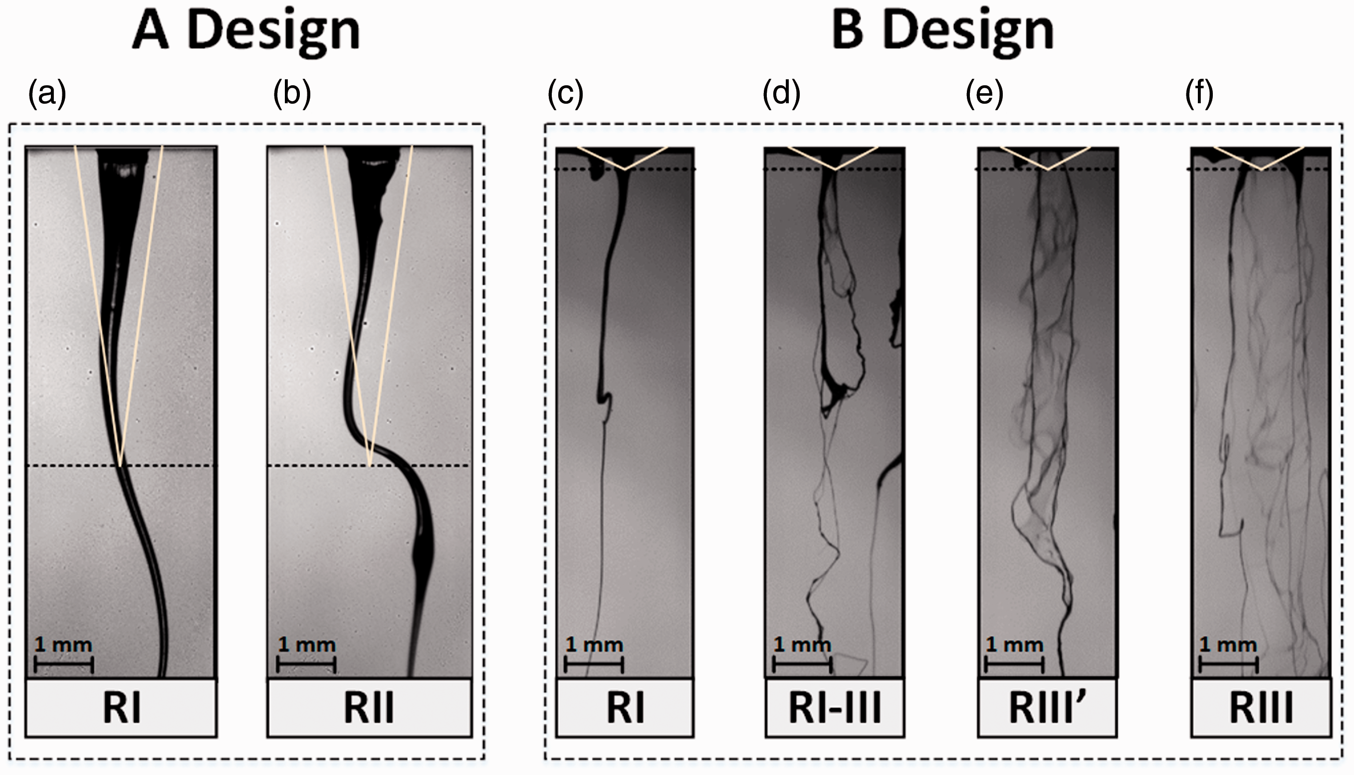
Coefficient of variation of the fibre diameter calculated at the freezing point, normalized die drool area (NDDA) and its standard deviation calculated at

Boldface indicates Shot-Production Region.
After analysing the videos recorded with the high-speed camera, it was observed that the shot was produced under certain operating conditions and after a critical mass of polymer had accumulated at the nozzle tip, forming an adhesive lump which subsequently descended and caused large fibre oscillations. The accumulation of extrudate at the nozzle tip is a phenomenon termed as die drool [23]. There are two distinct mechanisms that lead to die drool. The first one takes place inside the adhesive capillary (internal) and the second one takes place at the nozzle exit region (external). Whereas negative pressure gradients at the nozzle exit region can lead to external die drool, internal die drool is caused by molecular-weight fractionation of the polymer [23]. Die drool (or die build-up) can be quantified by measuring the Normalized Die Drool Area (NDDA) by use of Digital Image Analysis (DIA) [23,24] and is defined as:
The descent of the accumulated mass at the nozzle exit causes parameter
Normalized Die Drool Area as a function of time: (a)
The previous observations are in agreement with past research on shot formation, which establishes that the polymer’s molecular weight, which is a measure of internal die drool, as well as the air tilt angle, which is a measure of external die drool, are some of the main parameters that explain this phenomenon [26]. Regarding the formation of shots and internal die drool, morphological differences in the internal structure of fibre strands and shot particles have been observed by use of scanning electron microscopy [9]. However, to the author’s knowledge, no study has reported results on the molecular weight distribution of shot particles. Jiri Drabek and Martin Zatloukal [22] determined the fibre diameter’s coefficient of variation
Our studies suggest that the measures that show to be effective in reducing die drool will also help to minimize the formation of shots. Some of these include reducing molecular fractionation, minimizing material degradation, reducing the contents of lubricants or waxes and supplying clean hot air around of the extrusion orifice [23].
Figure 13 shows a representative sequence of frames taken in experiment A2 (RII), in which the shot formation was captured. This sequence of frames illustrates not only the shot formation but also the descent process through eight milliseconds of recording time, where the time shift between two consecutive frames is of about one millisecond. In this figure it can be observed how the shot descends across the freezing point

Sequence of frames presenting the shot formation process, taken from experiment A2, with a time shift between frames of 1 ms.
Although there are operating conditions under which shots do not form, such as in experiment A3, and there are yet others under which there is enough evidence to show that they do form, such as in experiment A4, there are nevertheless some operating conditions under which shots form to a lesser extent, as some other experiments show. One of these examples is shown in Figure 14, which depicts the adhesive pattern obtained in experiment A7, for which the calculated

Adhesive pattern obtained for experiment A7, which corresponds to
The results obtained in the previous and present sections indicate that there is a compromise between the geometric parameters of the nozzle and the operating conditions, both of which determine fibre breakup and shot formation. Finally, it should be mentioned that the conclusions that emerge from the present work on shot formation will be valid only for the adhesive being studied.
Concluding remarks
In this article, fibre deformation and shot formation were studied in the melt blowing process at the nozzle exit region on two multihole nozzle designs from an experimental point of view. To this end, the fibre dynamics were captured by using HSI for various operating conditions, which were taken from real industrial hot-melt adhesive applications for hygiene products.
On the one hand, it was shown that fibre breakup occurs as a result of applying a sufficiently large force in the direction perpendicular to the fibre. On the other hand, it was shown that the root cause of fibre shots is the accumulation of mass at the nozzle exit region (die drool), which consequently increase the variation in the final fibre diameter. Fibre shot can be quantified by means of the coefficient of variation of the fibre diameter
The results suggest that both the nozzle geometry and the operating conditions determine whether fibre breakup will occur and whether shots will be produced. Concerning the operating conditions, we concluded that increasing values of either the air-polymer flux ratio or the polymer temperature contributed to breaking the fibre and also facilitated the formation of shots. Concerning nozzle geometry, the results indicate that increasing values on the air duct tilt angle
Further study of fibre breakup and shot formation in the melt blowing of adhesives with different compositions other the one used in the present work or on different nozzle designs would provide a better understanding of these two defects, which would ultimately permit nozzle technology to be improved for use in the blown fibre production.
Supplemental Material
sj-pdf-1-jit-10.1177_1528083720949276 - Supplemental material for Experimental study of fibre breakup and shot formation in melt blowing nozzle designs
Supplemental material, sj-pdf-1-jit-10.1177_1528083720949276 for Experimental study of fibre breakup and shot formation in melt blowing nozzle designs by Ignacio Formoso, Alejandro Rivas, Gerardo Beltrame, Gorka S Larraona, Juan Carlos Ramos, Raúl Antón and Alaine Salterain in Journal of Industrial Textiles
Footnotes
Acknowledgements
The authors are grateful for the support of Cátedra Fundación Antonio Aranzábal-Universidad de Navarra. The authors also want to acknowledge Juan Villarón for his immense help in making the HSI recordings.
Declaration of conflicting interests
The author(s) declared no potential conflicts of interest with respect to the research, authorship, and/or publication of this article.
Funding
The author(s) disclosed receipt of the following financial support for the research, authorship, and/or publication of this article: This work was supported by VALCO MELTON; and Ministerio de Ciencia e Innovación, Gobierno de España, RETOS-COLABORACION 2019 (RTC2019-007057-7).
Supplemental Material
Supplemental material for this article is available online.
References
Supplementary Material
Please find the following supplemental material available below.
For Open Access articles published under a Creative Commons License, all supplemental material carries the same license as the article it is associated with.
For non-Open Access articles published, all supplemental material carries a non-exclusive license, and permission requests for re-use of supplemental material or any part of supplemental material shall be sent directly to the copyright owner as specified in the copyright notice associated with the article.