
Abstract
The aim of this study is to develop and investigate mechanical properties of knitted unidirectional thermoplastic composite prepregs. Knitted prepregs were fabricated by using thermoplastic yarns (high density polyethylene and polypropylene) and high performance yarns (kevlar, basalt and carbon) in double jersey inlay structure. This is a new approach to combine the reinforcing fiber with resin forming thermoplastic fiber during the knitting operation. The structures were stacked further in three stacking sequences at different angles (0/0/0/0, 0/90/0/90, 0/90/90/0), and hot compression was used to convert them into composite prepregs by melting the thermoplastic component. Mechanical properties e.g. tensile strength and modulus, flexural strength, flexural modulus, impact energy absorbed etc. were investigated in detail. Full factorial experimental design was used in order to study the effect of main yarn, inlay yarn and direction of stacking/plying on mechanical properties of composites. Analysis of variance (ANOVA) was conducted by Minitab 17 software to estimate the significance of testing direction (T), type of inlay yarn (I), type of main yarn (M) and stacking sequence (S) on mechanical properties. Overall highest tensile and flexural strengths were observed for Carbon fiber based samples followed by Kevlar and Basalt respectively. Theoretical estimation of elastic modulus shows similar trend as the experimental results. The inter-laminar shear strength is maximum when the fiber orientation changes in each layer. Type of main yarn and inlay yarn have significant contribution on impact related properties. Depending upon type of material, these composites can be used in aerospace, automotive, civil and sports goods.
Introduction
Direction of fiber orientation plays a crucial role in deciding mechanical performance of textile reinforced composites. Unlike conventional isotropic materials, textile structures can be designed and developed for load bearing in a particular direction. Their properties can be enhanced by modifying the structure and material composition. The resin is a polymeric material which is used to impregnate the fibrous structure. Thermoset resins are widely used for high stiffness, temperature resistance and chemical resistance etc. However, they also have several disadvantages like high brittleness, lower toughness etc. [1]. On the other hand, thermoplastic resin based composite materials offer several advantages like high fracture toughness, recyclability, short manufacturing process, weldability and lower cost [2]. Using thermoplastic resins can reduce weight of composite parts and thus can replace traditional materials such as wood, thermoset resin based or metal-based components without compromising structural stability and mechanical performance. Researchers investigated mechanical properties of thermoplastic composites produced from hybrid yarn (52% Glass & 48% polypropylene) knitted fabric developed on flat bed knitting machines. They concluded that properties are affected by the arrangement of yarn in the reinforcement. Mechanical properties are superior in the direction in which the hybrid yarns were used [2]. Other researchers developed unidirectional (UD) composites by winding parallel sheets of yarn on a metallic frame [3]. Significant increase in mechanical properties was observed in composites reinforced with jute and polypropylene (PP) braided textiles in comparison with virgin PP. Efficient infusion of resin around the jute fibers and enhancement of mechanical properties was observed by using micro braiding technique [4,5]. Such composite materials are preferred to be used as lining in personal body armor. Polypropylene based composites are preferred for bumpers, front, back and side protections and spoilers in automotive. Researchers have studied mechanical properties of PP film-based UD composites developed by similar techniques [6]. Thermoplastic composites were developed in a single step process in which heat and pressure were applied on UD tapes of fabricated reinforcement. Higher viscosity of thermoplastic resins as compared to thermoset resins at lower temperatures makes their penetration difficult through the reinforcement materials [7]. Producing complex shapes involves plying reinforcement on the mold with large amount of waste. There is large variability in resulting structure due to variations in placement of reinforcement. There is also local uncertainty in uniform distribution of fiber volume fraction [8]. New and advanced techniques for composite manufacturing are developed through automated fiber placement (AFP) and are preferred for use in high end applications like aerospace, and automotive. AFP provides high speed of deposition, accuracy of fiber alignment, higher automation, repeatability, lower chances of any variation, lower material wastage and involves less joints during manufacturing of component parts [9,10]. AFP systems are used for building 3-dimensional (3D) components like wing panels and fuselages in aircrafts. During cutting and layering with hand layup process for 3D structures, there is a lot of waste which can be eliminated by AFP. Suong Van Hoa et al. found that residual stresses are generated due to miss-match in shrinkage of fibers in different directions and may cause distortion in the composite product shape and dimensions. The AFP technology has a limitation in producing components due to mismatch of shrinkage of fiber in different directions [9]. When multiple layers are laid together by AFP, different layers are laid at different times which create difference in temperature and thus distortion of flat composite panels.
Composite reinforcement materials which are already impregnated through thermoplastic or thermoset resin are known as prepregs. Prepregs have a shorter manufacturing process and they are cured by hot compression molding. These are most commonly prepared by hand layup method in aerospace composite industry. Different plies are cut using software like Fibersim or Catia CPd according to defined geometry of the components. Then these prepreg components are laid in the mold manually. In automated fiber placement (AFP) method, the prepregs are laid layer by layer. Thus the inner most layers cool down significantly quickly and temperature falls below Tg (glass transition temperature), resulting in a lower shrinkage (due to shorter cooling time) as compared to outer layers. This shrinkage mismatch is a disadvantage. It can be minimized by maintaining the temperature above Tg, or adjusting speed so as to avoid quick cooling of inner layers. Other limitations of thermoplastic prepregs produced using AFP include variation in roller pressure, variation in the thickness of tow and increase in width. Laser enabled heating is applied immediately after the pressing roller, in order to facilitate flow of resin through the fibers.
One major challenge in producing composites with superior mechanical properties at reasonably lower price is cost effective prepreg. Composites constructed from unidirectional reinforcement perform better than randomly oriented fibers but the cost is very high [11]. Thermoplastic prepregs are advantageous over thermoset composites as they don’t require 2nd stage curing process. Prepreg based composites produced through AFP show several advantages e.g. superior mechanical properties in a specific direction, shorter manufacturing cycle, less wastage during processing etc. In literature there is limited information about knitted prepregs from thermoplastic components [12–15]. Therefore, the current study is focused on development and investigation of mechanical properties in knitted unidirectional thermoplastic composite prepregs. Low cost, high productivity, longer shelf life, ease of manufacture and desired fiber volume fraction in UD thermoplastic prepregs can be achieved using this unique manufacturing method. It will be a continuous process suitable for bulk production and prepregs can be stored and transported without shelf life issues.
The design of experiment (DOE) is one of the widely used statistical techniques due to its quick response [16–18]. In full factor experimental design, the effect of two or more factors can be assessed on response simultaneously [19]. In this technique analysis of variance (ANOVA) examines the fitting, significances and precision of the model [20]. In the current study, full factorial experimental design was used to determine the effect of experimental factors on the response variables (tensile, bending and impact properties).
Methodology
Materials
The prepregs were fabricated using five different types of fiber materials which include polypropylene (PP), high density poly ethylene (HDPE), kevlar, carbon and basalt. The PP yarns were purchased from a local supplier Al-Khair (HMD) Industries Pvt. Ltd, Karachi, Pakistan, HDPE yarns were purchased from Kaitai Special Fiber Technology Co., Ltd., Zhejiang, China, kevlar was obtained from Escorts International, Faisalabad, carbon from Jiaxing ACG Composites Co., Ltd., Zhejiang, China and basalt from GBF basalt fiber Co., Ltd., Zhejiang, China.
The two types of thermoplastic materials i.e. polypropylene and high density poly ethylene were used as resin in all the knitted structures during heat treatment. The linear density of both types of thermoplastic yarns used was 600 Denier.
Remaining three types of high performance yarns were used as reinforcement and as inlay yarns in the knitted structures developed. Kevlar is an aromatic polyamide fiber which is very strong and resistant to heat. It has 85% of the amide linkage attached directly between aromatic rings. When compared with same weigh of steel and glass fibers, kevlar fibers have much superior mechanical properties. Carbon fiber refers to materials having at least 92% (mass fraction) of carbon. They have several advantages like high stiffness, high tensile strength, low weight, high chemical resistance, high heat tolerance and low thermal expansion. Basalt is a mineral based fiber composed of plagioclase, pyroxene and olivine among many other metal oxides. The basalt yarn is made from extremely fine fibers and similar to fiberglass, having much superior physio-mechanical properties. It is also significantly cheaper than carbon fiber. Like carbon and glass, it is widely used in fireproof textiles for the aerospace and automotive industries. All the inlay yarns used in this study are with similar linear density of 5400 Denier.
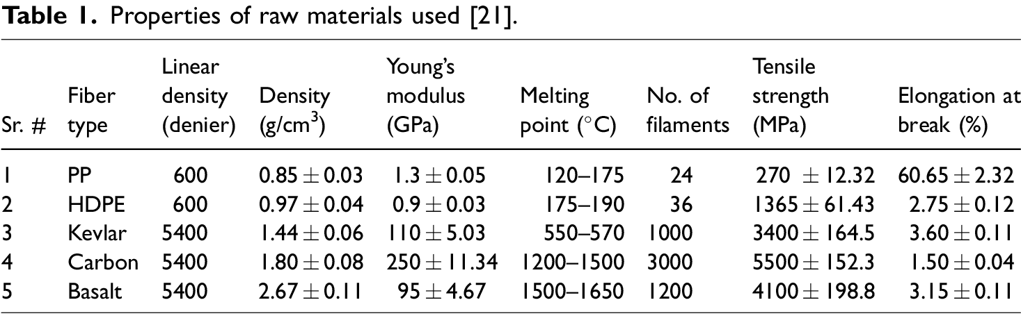
Properties of the materials used in this study are given in Table 1.
Properties of raw materials used [21].
Methods
The methodology adopted in this research is depicted in Figure 1.

Process for manufacturing and characterization.
DOE and statistical analysis
The full factorial experimental design was used to analyze the influence of main factors and their interactions on tensile, flexural and impact properties of developed composite prepregs. Two factors (inlay yarn type and stacking sequence) were chosen with three levels each and one factor (thermoplastic yarn type) was chosen with two levels in order to perform the design of experiment. Thus, a total of 18 (3 × 3 × 2) samples were developed. The factors and levels are given in Table 2. The statistical analysis of data was carried out using Minitab 17 software.
Experimental factors and their levels.

The design of experiment is shown in Table 3.
Design of experiment.

The response variables are tensile strength, tensile modulus, bending strength, bending modulus and impact energy absorbed.
Knitting
Knitting of above selected materials was carried out on a double bed electronic flat-bed knitting machine with 2 cams, 8 feeders and gauge 7. Plain inlay structure is used for knitting as given in Figure 2. Thermoplastic yarns (HDPE and PP) were used as main knitting yarn and high performance yarns (Kevlar, Basalt, Carbon) were used as inlay yarn.

Plain rib inlay structure.
The 4 layer stacking of samples was done in 3 sequences namely (0/0/0/0), (0/90/0/90) and (0/90/90/0) degree orientations. A schematic is shown in Figure 3.

Stacking sequences.
Hot compression
High pressure and heating was applied to the knitted structures by using hot compression device. Knitted specimens were cut into required dimensions (30 cm × 30 cm) and then placed layer by layer in defined stacking sequence as per DOE. A temperature of 180°C and pressure of 6 bars was applied [22–24]. In order to achieve the target density and thickness with homogeneity, the pressure was selected accordingly. All specimens were allowed to cool with applied pressure until temperature reduces to 70°C–80°C and then were removed from machine. The hot compression device is shown in Figure 4.

Hot compression device.
Characterization
Physical parameters
Stitch length which is the length of yarn used to produce one stitch [25] using main knitting yarn was measured using stitch length tester. Stitch density is number of stitches per unit area i.e. cm2, measured by a magnifying counter glass. Areal density is expressed as grams per square meter (GSM) and measured according to international standard ASTM D3776 [26]. Fiber percentage of the final composite was calculated using ratio of inlay yarn to the fabricated knitted sample, as the thermoplastic component formed the resin after hot compression. Ratio of inlay and binder (thermoplastic) yarns can be changed at knitting stage by changing stitch length.
Physical parameters of all knitted composite prepreg specimens are given in Table 4. Fabricated knitted samples were used to produce UD composite prepregs by using in different stacking sequences.
Physical parameters of all specimens.

Scanning electron microscopy
Scanning electron microscopy (SEM) was done for the composite prepregs after mechanical testing. The samples for scanning electron microscope were prepared with Quarum Q150R ES, which uses gold-plating with argon gas atmosphere. The thickness of gold plating was 2 nm using a sputter current of 20 mA.
The scanning electron microscope TESCAN MIRA 3 GME was used for this purpose. The samples were visualized in nitrogen atmosphere with SE (secondary electron) detector, with acceleration voltage of 10 kV. The working distance was maintained at 16–32 mm with scan mode. The magnification used was 100×.
Tensile properties
Tensile strength and modulus of all composite prepregs were determined according to standard procedure of ASTM D3039 on the Zwick/Roell universal tensile tester. The testing device works on principle of constant rate of elongation (CRE) which was set to 2 mm/min. Vernier caliper was used before testing to measure the thickness of each specimen. Tensile strength gives the in plane mechanical behavior of the composite materials. A thin flat strip of prepreg sample having a constant rectangular cross section i.e. 20 cm × 2.5 cm dimension, was mounted in the grips of the universal tensile tester and monotonically loaded in tension while recording load. The effective gauge length of test samples was set as 10 cm × 2.5 cm. Maximum load of the specimens was noted before fracture or failure. By monitoring the strain and load of the specimens, the stress strain response was plotted, From this plot, the tensile modulus and ultimate tensile stress were calculated. The universal tensile tester is shown in Figure 5. For each sample 10 measurements were carried out. The mean and standard deviation were calculated.
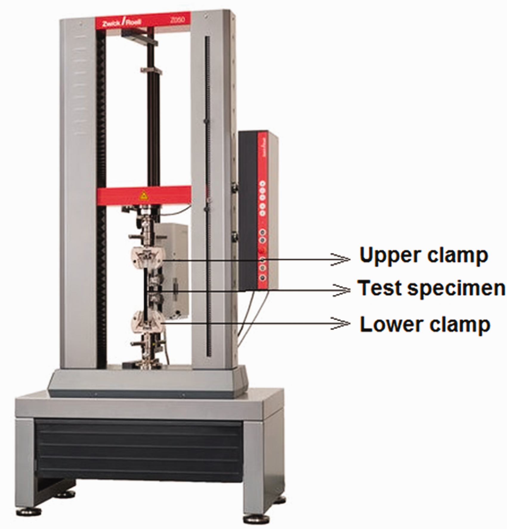
Universal tensile tester.
Theoretical calculation of elastic modulus
The tensile modulus of a fiber reinforced composite can be calculated by using rule of mixture if the corresponding values for the constituent fiber and matrix are known. The tensile modulus of a unidirectionally reinforced composite in longitudinal (parallel) direction can be calculated based on equation (1).
Bending properties
The flexural properties of composite prepreg samples were evaluated using 3-point bending test according to standard test method ASTM-D7264. Machine speed was set to 1 mm/min and force was continuously applied on the specimen until it fractures or the value of force reduced to 40% of maximum force [27–30].
The Zwick/Roell universal testing device was used by changing the clamps. It measures the flexural stiffness and strength properties of polymer matrix composites. A specimen of rectangular shape having dimensions 120 mm × 13 mm was supported at the ends and deflected at the center point. As force was applied on the specimen it started deflecting from center, its deflection and force were measured and recorded until the failure occurred or the maximum force reduced to 40%. For each sample 10 measurements were carried out. The mean and standard deviation were calculated. The principle of 3-point bending is shown in Figure 6.

3-point bending principle.
The gauge length/support span of 80 mm, deformation rate of 1 mm/min and load of 5 kN was maintained. The flexural strength was calculated using the equation (2).
Flexural modulus was calculated using equation (3).
Where, P represents Load, L represents gauge length, b represents width, h represents thickness and y represents deflection during bending.
Impact properties
The impact test was performed according to international standard ASTM D7136 on the Zwick/Roell drop impact tester. A predetermined weight (1.04 Kg) and height was determined accordingly for 10 Joule impact energy. The weight was allowed to strike on composite specimens which were supported on a horizontal platform with clamps on the edges.
This test was used to measure the damage resistance of composite prepregs against a drop weight impact event. A flat rectangular sample of dimension 15 cm × 10 cm was subjected to concentrated impact using a drop weight device. Potential energy of the impactor was pre calculated by weight and height of impactor. Damage was imparted through out of plane, concentrated impact which is perpendicular to the plane of sample. For each sample 10 measurements were carried out. The mean and standard deviation were calculated. The device and principle of impact energy absorption are shown in Figure 7.

Zwick/Roell drop weight impact tester and principle of energy absorption.
Impact energy was calculated as,
Impact energy absorbed = Energy of striking impactor – Residual energy of rebounding impactor
Inter laminar shear strength of prepregs
The inter laminar shear strength of the prepregs was determined using short beam shear strength test according to standard ASTM D 2344. It is used to evaluate the influence of fiber–matrix bonding on the inter laminar shear strength (ILSS) at a laminate level but as a mesoscale characterization [31–33]. It is a simple mode II transverse shear loading test that is meant to measure the quality of interfacial bonding. Figure 8 shows a schematic of the ILSS test in which the support span (S.S) length-to-thickness (h) ratio is 4:1. The test was carried out under a three-point monotonic flexural loading condition. For each sample 10 measurements were carried out. The mean and standard deviation were calculated.

ILSS using short beam shear strength test.
The ILSS is given by equation (4).
Where
Results and discussion
Morphological structure analysis
Morphological analysis was performed for all the specimens in order to ensure uniform impregnation of resin through the fibers in yarns. Macroscopically, it was observed that thermoplastic resin distributed uniformly among all plies and between filaments of yarns. No visible voids were found. The scanning electron microscopy was used to study details of fiber and resin interface. The SEM images are shown in Figure 9.

Scanning electron microscopy (SEM) images of prepregs developed.
It can be observed that the resin infusion through the inlay yarns is mostly uniform. In some cases of (0/90/90/0) layering sequence, the impregnation through cross directional yarns are not sufficient. As the prepregs are only intermediate products, the impregnation can be improved when the final composites will have higher portion of resin.
Composite prepregs produced were characterized in both parallel and cross direction for the various mechanical properties. Results of characterization are given in Table 5.
Mechanical characteristics of the composite prepregs.

Tensile properties
The tensile stress-strain behavior was studied and characterized. Representative curves are shown in Figure 10.

Tensile stress-strain curves of prepreg samples in parallel and cross direction. (a) Kevlar prepregs (parallel). (b) Kevlar prepregs (cross). (c) Basalt prepregs (parallel). (d) Basalt prepregs (cross). (e) Carbon prepregs (parallel). (f) Carbon prepregs (cross).
The PP impregnated kevlar and carbon reinforced samples generally show relatively superior tensile properties as compared to HDPE based prepregs. This can be attributed to relatively higher Young’s modulus of PP as compared to HDPE. There is an exception in basalt which may be due to relatively poor interface of basalt with PP. It is because basalt is an inorganic fiber and may not have that strong interface with organic resins like HDPE or PP. This can be seen from the SEM images in Figure 9.
The 1st stacking sequence (0/0/0/0) results in maximum strength and modulus in the parallel direction. This is due to the orientation of all the reinforcing fibers along the principal axis and thus being able to contribute towards load sharing. However, the results in the cross direction are interesting. The 2nd stacking sequence (0/90/0/90) shows best tensile performance as there is uniform sharing/distribution of fiber orientation along both the principal axes. A comparative account of tensile strengths and modulus of all the prepared samples are given in Figures 11 and 12, respectively.

Tensile strength in (a) parallel and (b) cross direction.

Tensile modulus in (a) parallel and (b) cross direction.
The carbon based PP impregnated sample shows highest tensile strength when all fibers are oriented along the principal axis. As kevlar fibers have lowest tensile strength among the three types of reinforcing fibers, their composite prepregs with HDPE and PP also show relatively lower tensile strength compared to basalt and carbon. Results shown in Figures 11 and 12 indicate that, highest tensile strength & modulus were observed in all material compositions when the plies were stacked in the same direction i.e. 1st stacking sequence. The strength in the direction parallel to direction of plies is higher than the tensile strength in the cross direction. Among the different types of reinforcing (inlay) yarns, carbon fiber based composite prepregs show highest tensile strength followed by basalt fiber reinforced samples and kevlar based samples respectively. This is in line with the basic mechanical properties of these constituent yarns.
Between the two types of binder (thermoplastic) yarns, PP based samples show higher tensile strength as well as modulus both in parallel and cross direction as compared to their HDPE components. It can be attributed to higher modulus of PP with respect to HDPE. Lower tensile strength and modulus was observed in all specimens when tested in cross direction as there was no binding of the reinforcement component perpendicular to fiber axis. Cross direction shows strength of only thermoplastic material i.e. resin. The second plying sequence (0/90/0/90) in general shows higher strength and modulus compared to third direction of stacking (0/90/90/0) in all material types. This can be attributed to uniform distribution of load to resin in alternative plies in second stacking sequence as compared to 3rd stacking order. In the third stacking sequence, group of two plies are stacked which might cause stress concentration and possible delamination. This fact is also supported by the SEM images which show more homogeneity in case of (0/90/0/90) stacking. Comparable values of tensile modulus are observed in cross and parallel direction in second and third stacking sequence due to averaging effect and contribution of the inlay yarns in load bearing. A great difference of tensile strength and modulus in first stacking sequence was observed when composite prepregs were tested in parallel and cross direction. Carbon based specimen in first stacking sequence shows the least value of extension followed by basalt and kevlar which again is due to inherent material properties of these inlay fibers.
Fractography analysis
The samples fractured during tensile test were analyzed for studying the nature of failure. Images in Figure 13 show the fracture of samples broken during tensile testing.

Fracture during tensile failure of prepregs.
The fractures in parallel direction are shown inside ovals and the damge in cross direction are shown inside rectangles. It can be mostly seen that, there occurs a brittle fracture in the parallel direction due to fiber breakage. A smooth line indicates uniform distribution of load between the fibers. However, in the cross direction, the failure is mainly due to slippage of fibers and failure of the resin. The fractures in carbon based prepregs are more prominent due to relatively lower strain. Sometimes there is longitudinal splitting if the bonding/interface with resin is not strong enough.
Comparison of theoretical elastic modulus and experimental modulus
The theoretical elastic modulus of the composite prepregs was calculated in the parallel direction with stacking sequence (0/0/0/0) based on rule of mixture as shown in equation (1). The results are given in Table 6.
Theoretical elastic modulus of the composites based on rule of mixture.

The measured values of elastic modulus are very low compared to the one of the reinforcement fiber. The fibers are highly crystalline with relatively smaller amorphous segments. Further the extremely small cross-section of individual fiber results in a higher elastic modulus. However a macroscale composite prepreg is composed from many layers of fibers surrounded by a much weaker (low modulus) resin. Thus the modulus of the composite prepreg is much lower.
The theoretical values calculated are based on the assumption that all fibers are parallel to the axis and contributing towards load bearing and there are no slippages between the fibers. Whereas in reality, there are variations in direction of the inlay yarn. They may not be exactly parallel to the axis. Further the calculation is based on elastic modulus of resin fiber and in real samples; the fibers have been melted into matrix. All these could be reason for much lower practical Young’s modulus as compared to theoretical value. A comparison of the theoretical and actual elastic modulus is shown in Figure 14.
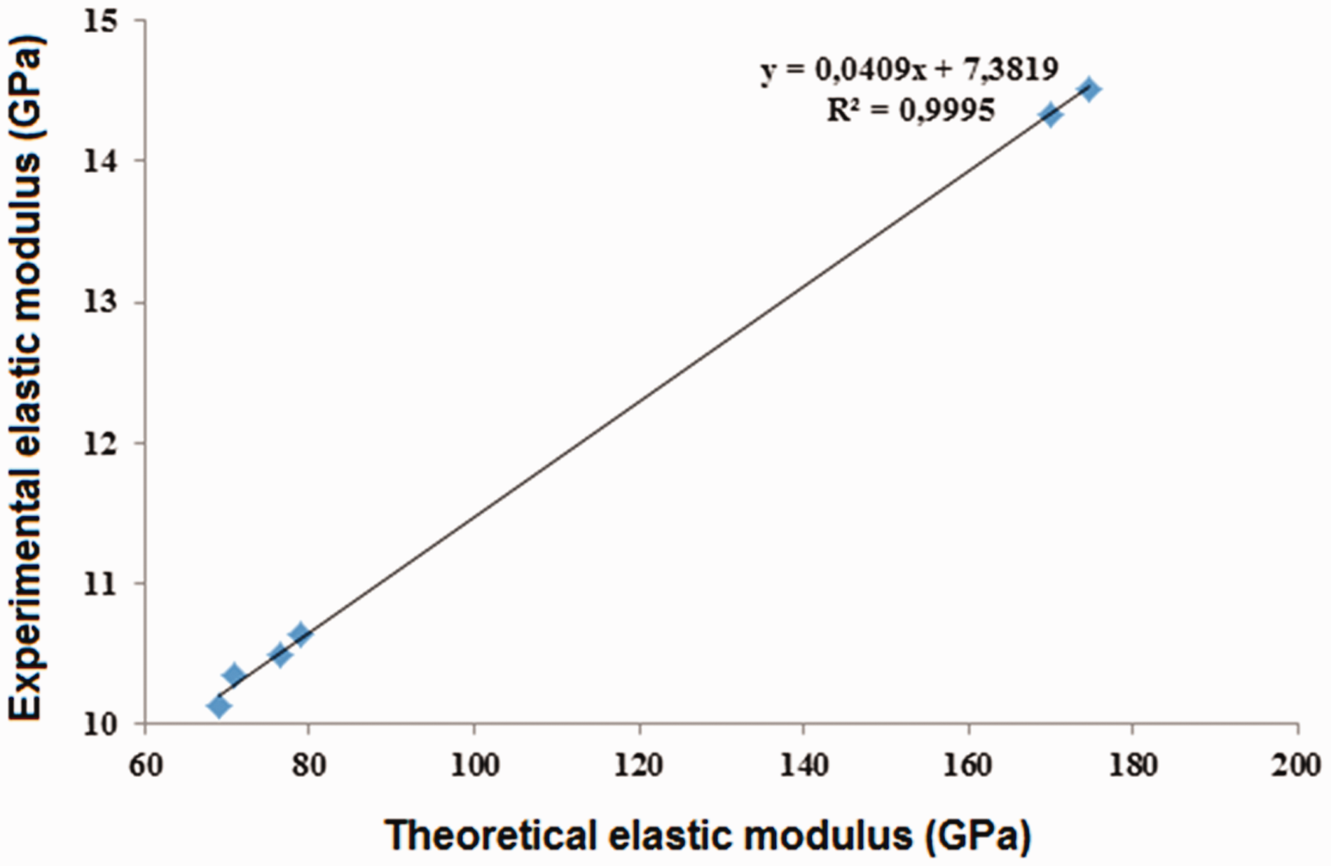
Comparison of theoretical and actual elastic modulus of prepregs.
Though the ranges of values are quite different, but the interesting and important fact is that both the theoretical and experimental elastic moduli have the similar trend with a very high correlation. This signifies that the elastic modulus of the prepregs is in line with material intrinsic properties.
Flexural properties
The flexural strength and flexural modulus of all the specimens is shown in Figures 15 and 16, respectively.

Bending strength in (a) parallel and (b) cross direction.

Bending modulus in (a) parallel and (b) cross direction.
Substantially higher flexural strength was observed in all the materials for 1st stacking sequence in which the plies were laid parallel to the axis. This is proportional to the tensile modulus as majority of reinforcing fibers are laid in the parallel direction. Minimum flexural strength was observed in the cross direction for the same specimens manufactured in 1st stacking direction i.e. all plies were laid in parallel direction but tested in cross direction. Similar to tensile properties, the bending strength in cross direction is higher in case of (0/90/0/90) stacking due to homogenization of the reinforcement as compared to (0/09/90/0) sequence which might lead to delamination during loading. An asymmetrical stacking (0/90/0/90) may induce some coupled effect like torsion or in-plane shear during flexural testing. This might influence flexural properties of asymmetrical stacking (0/90/0/90) as compared to the symmetrical stacking (0/90/90/0).
Bending properties in the prepregs seem to be more dominated by the stacking sequence and inter-fiber friction bonding with the thermoplastic component rather than the fibers reinforcing them. Basalt and carbon based composite prepregs show higher stiffness compared to kevlar based panels for both kinds of binding (thermoplastic) yarns. This is due to higher number of constituent filaments in basalt and carbon as compared to kevlar for the same linear density. Higher number of constituent fibers/filaments leads to higher frictional restraint and higher resistance to bending. Carbon and basalt fibers have higher density as compared to kevlar fibers. Further these two yarns are composed of higher number of filaments for the same overall linear density of all yarns. This means that the diameter of carbon is minimum followed by basalt and the maximum diameter is in case of kevlar fibers. The relative surface area responsible for inter filament friction is higher for smaller diameter fibers like carbon and basalt. This cumulative friction between constituent filaments significantly influences the resistance to bending deformation.
In the cross direction, higher flexural strength and modulus was observed in all materials for the 2nd stacking sequence (0/90/0/90) as compared to the 3rd sequence (0/90/90/0) as the reinforcement plies were alternative to each other and help in uniform load bearing. During flexural testing of specimens with 3rd stacking order, fractures might initiate in between two cross layers which are placed perpendicular to the testing direction. In the 2nd stacking sequence, there is more uniform stress distribution and a higher stiffness is observed without generation of fractures. This is also supported by the uniformity of samples with 2nd stacking sequence as observed in the SEM images.
Impact properties
Upon drop impact, the samples did not break and rather the impactor rebounded with residual energy. The absorbed energy can be calculated from force–displacement curves given in Figures 17 to 22. The structures and materials used in this study do not have any inherent crimp and thus their impact energy absorption is better than wavy/crimped yarns. Such findings were also reported in literature [34–36]. Amount of absorbed energy and maximum displacement was calculated for the prepreg specimens.

HDPE knitting yarn based prepregs with (0/0/0/0) stacking.

PP knitting yarn based prepregs with (0/0/0/0) stacking.

HDPE knitting yarn based prepregs with (0/90/0/90) stacking.

PP knitting yarn based prepregs with (0/90/0/90) stacking.

HDPE knitting yarn based prepregs with (0/90/90/0) stacking.
PP knitting yarn based prepregs with (0/90/90/0) stacking.
Force versus displacement response
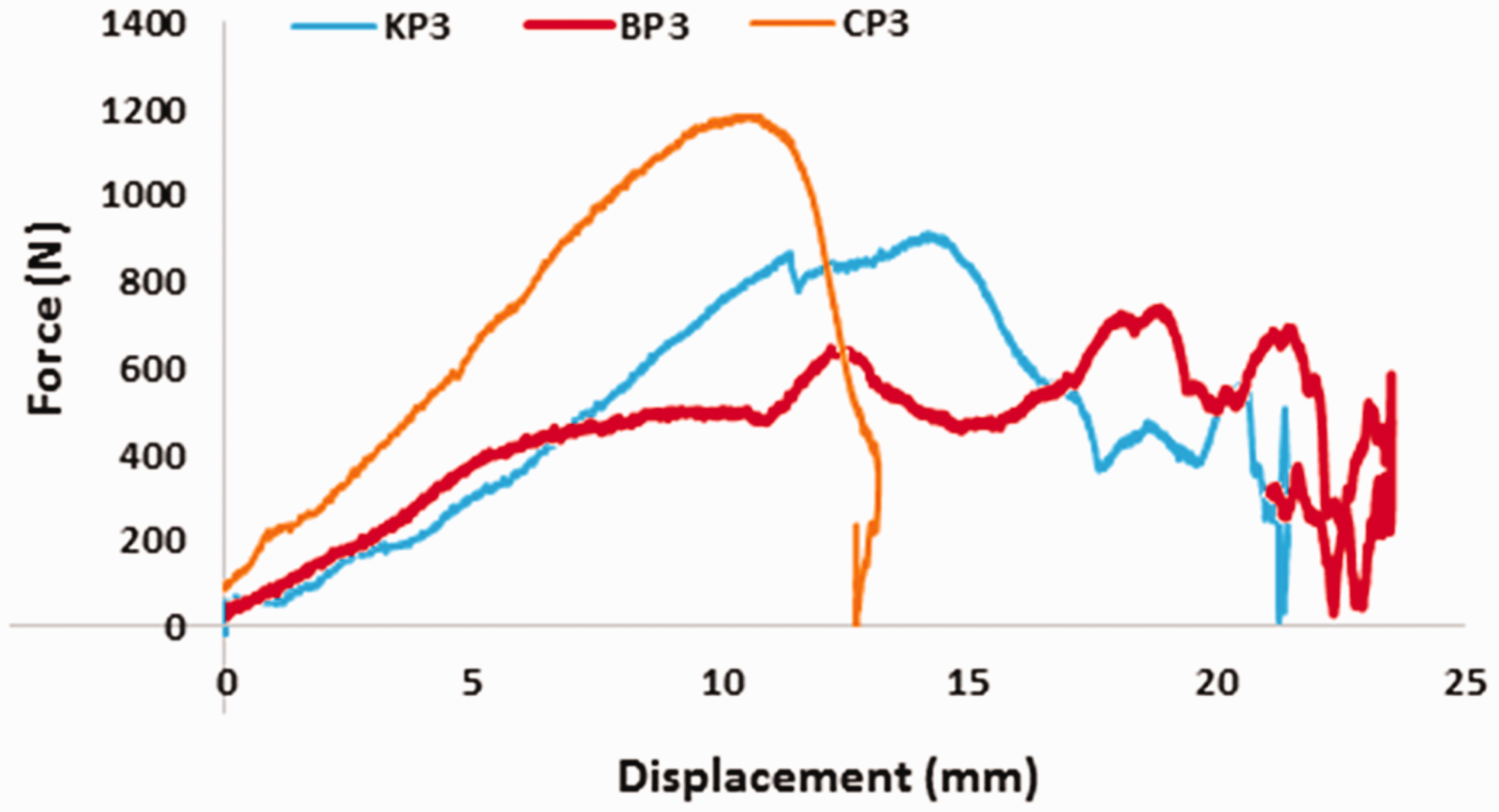
For evaluation of drop impact performance in composite prepreg samples, absorbed energy values were evaluated. It is the difference in kinetic energy of striker/projectile right before impact and after impact. Absorbed energy is dissipated by the specimen through several mechanisms. There are elastic and plastic deformations in composite panels during impact. The force displacement curves in Figures 17 to 22 are segregated by different knitting yarn and stacking sequences. By calculating the area under force displacement curve, the energy absorbed can be calculated [33]. Kevlar, basalt, and carbon-based composites made of the same knitting yarn (HDPE/PP) and same stacking sequences are compared.
It is visible that carbon based samples have lower displacement and thus lower energy absorption after impact. In all the prepreg sample, the (0/0/0/0) stacking shows minimum impact force but maximum energy absorption due to maximum displacement. The (0/90/0/90) as well as (0/90/90/0) sequences show higher impact force but lower displacement and thus lower energy absorption. This can be due to higher inter laminar shear strength. The shape of the curves for non-parallel sequencing is therefore more uniform showing higher peak. In parallel (0/0/0/0) sequencing, there is stick-slip effect which is observed by several peaks in case of all samples tested in this direction. The stick-slip is due to inter-fiber slippage as well as inter laminar slippage.
Carbon fiber reinforced specimens with second stacking sequence in which alternative plies were laid at 90° to each other, show better elastic behavior than other stacking sequences of the same inlay material. This may be attributed to higher inter-laminar strength when orientation of fibers is perpendicular to each other in adjacent layers. The deformation produced by striker/impactor is fully recovered in all the samples.
In all types of inlay, the non-parallel stacking also shows relatively higher resistance to deformation which enables it to absorb higher amount of energy compared to (0/0/0/0) stacking sequences. Overall energy absorbed by carbon specimens was relatively lower as compared to kevlar and basalt based specimens due to lower deformation of carbon fibers. Highest overall deformation was produced in first stacking sequence for all the material compositions due to orientation of inlay fibers in the parallel direction.
Impact energy absorbed
Energy absorption of a specimen is characterized into three stages. First stage is due to elastic deformation which forms dents [34,35] and for carbon specimen this is higher due to its greater elastic modulus. Stage-II of energy response in composite laminates is due to energy dissipation in form of intra-laminar damage, delamination (inter-laminar displacement) and friction between projectile/laminate and among neighboring plies within the laminate. Stage-III is denoted by transformation of the energy of impactor to damage and fracture of composite specimen. Energy loss by the impactor/projectile as shown in Schematic Figure 7 can be associated to the energy absorption by the composite structure, projectile deformation and heat generation due to friction. The impact energy is absorbed by fiber-matrix debonding, matrix cracking and subsequent failure/breakage of the reinforcement fiber [36,37]. The dominant energy absorption mechanism during projectile impact/penetration in multilayer composite panels is due to energy absorption through fiber failure/extension, matrix cracking and delamination. Absorbed energy is also an indication of the magnitude of damage. Figure 23 shows the impact behavior of all specimens.

Impact behavior of composite prepregs. (a) Impact energy absorbed. (b) Maximum displacement.
Kevlar based prepreg specimens show better energy absorption behavior as compared to carbon and basalt specimens. This is particularly interesting in contrast to the comparative tensile and bending properties. The superior impact behavior pertains to higher elongation/deformation at break of the kevlar fibers vis-à-vis basalt and carbon fibers. A higher deformation contributes towards higher shear resistance and resilience of the material when load is applied for very short time duration e.g. in an impact situation. Carbon fiber typically shows relatively lower deformation at break. This is a disadvantage as far as impact performance is concerned. Though carbon based materials have superior tensile properties, they do not seem to be as promising with respect to shear and impact.
Kevlar specimen shows higher impact energy absorption in 1st stacking direction i.e. when all plies are laid in same direction due to its high value of displacement along fiber direction. Carbon based laminates show improved energy absorption upon stacking in 2nd and 3rd sequence. This is attributed to homogenization of multilayered prepreg panels. There is also occurrence of interlaminar displacement which improves the energy absorption. For all types of inlay yarns, the specimens having multidirectional stacking sequence show better results due to greater energy dissipation resulting from homogenized fiber orientation along the axes and absorption of energy by failure of matrix phase.
Among the two types of thermoplastic yarns, PP proves to have better interface with kevlar and basalt in comparison with HDPE as far as impact performance is concerned. A relatively lower density and lower melting temperature of PP enables easy impregnation and uniform spreading of resin around the reinforcing fibers as seen from the SEM images in Figure 9. Superior mechanical properties are also attributed to higher Young’s modulus of PP compared to HDPE.
Maximum displacement
Highest maximum displacement was produced in Kevlar based specimens which also show maximum energy absorption. This is inherent to kevlar fibers elongation at break. In kevlar and basalt specimens, better energy absorption and maximum displacement is complimentary to fiber properties. In the 1st stacking sequence (unidirectional), the displacement is higher than the other two cases due to extension along fiber axis and maximum energy absorbed as compared with 90° angle stacking sequence. Energy absorption as well as peak displacement was decreased in basalt and kevlar specimens in 0/90 stacking sequence due to disorientation of fiber axis. In 2nd stacking sequence i.e. (0/90/0/90) for basalt and kevlar fibers, energy absorption was less than the 1st stacking sequence but better than 3rd sequence as reported in literature. This is due to uniform two-way energy distribution in alternative orientation of reinforcement of plies which does not hold good in third stacking sequence due to two inner plies in same direction.
Inter laminar shear strength
The inter laminar shear strength was determined based on short beam shear strength test with a support span (S.S) length-to-thickness (d) ratio of 4:1. The results are given in Table 7.
Inter laminar shear strength (ILSS) of prepregs.

A comparative account of ILSS is shown in Figure 24.
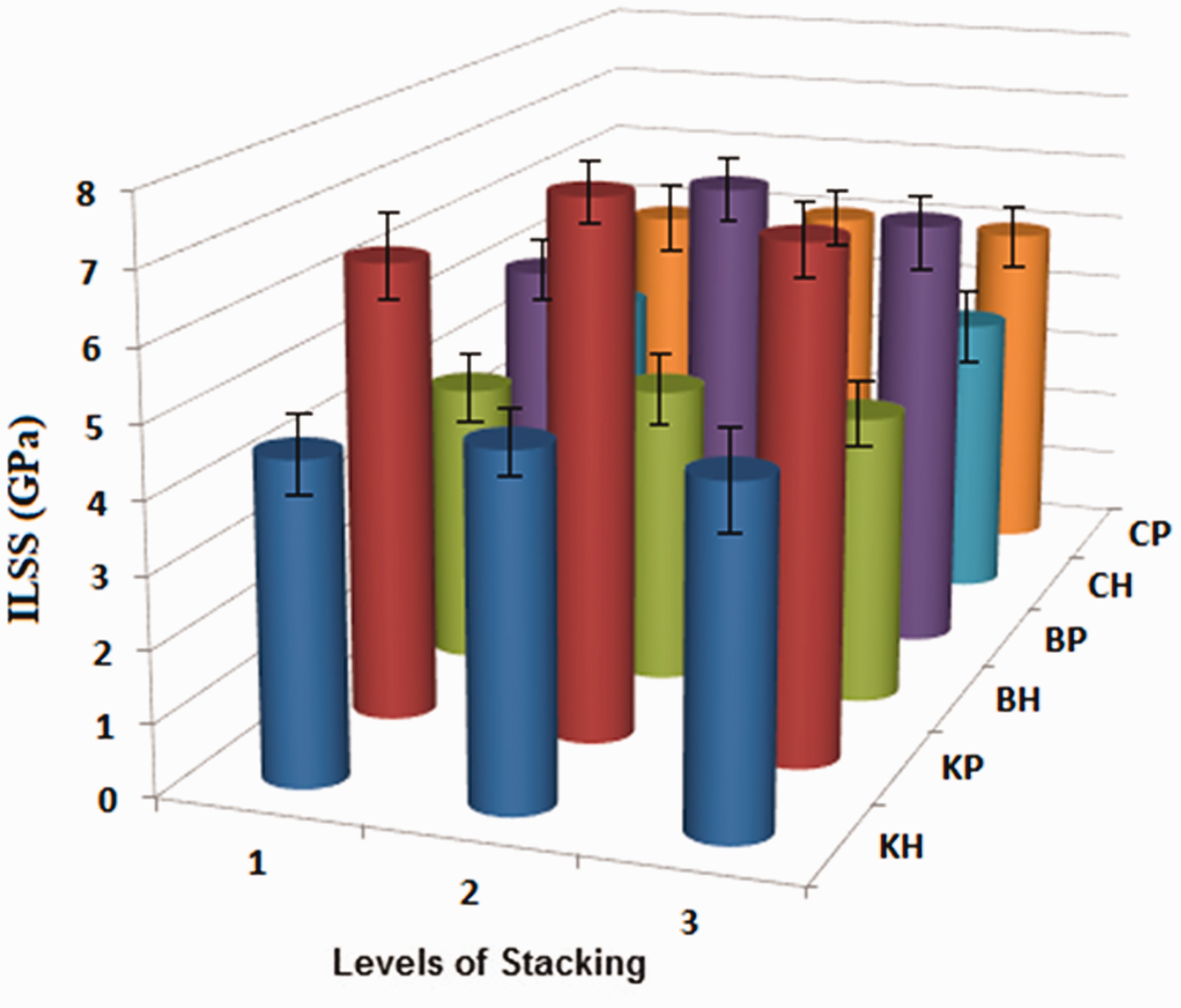
ILSS for the composite prepregs.
The inter laminar shear strength gives information about the bonding force between different layers of the prepreg. It is visible that PP based prepregs show higher ILSS as compared to HDPE based samples. This is reflection of higher elastic modulus of PP as compared to HDPE. PP spreads more easily and uniformly in between the layers due to its lower melting temperature and lower density. Among the various stacking sequences, it is visible that non-parallel stacking improves the ILSS in all kinds of inlay yarns. The second stacking sequence (0/90/0/90) results in highest ILSS due to higher homogenization of layers and least possibility of stress concentration between layers.
Analysis of variance
Analysis of variance (ANOVA) was carried out to determine the influence of the experimental parameters on tensile, bending and impact properties. The details are given in Table 8.
Analysis of variance and model summary.

ANOVA for tensile modulus shows P values of T, I and S i.e. testing direction, type of inlay yarn and stacking sequence are less than 0.05 which shows that contribution of these experimental variables on tensile modulus is significant. From two-way interaction T * I and I * S, the P values are less the than 0.05 which shows significant contribution of these interactions on tensile modulus. R-Sq value of tensile modulus indicates that 95.51% change in tensile modulus is related to factors analyzed.
For bending properties, P values of T, I and S are less than 0.05 which means there is significant contribution of these experimental variables on bending modulus. Whereas P value of M i.e. main yarn is greater than 0.05 which shows this experimental variable does not have any significant contribution on bending modulus. From two-way interaction of T * S, a significant contribution is shown because of its lower P value while other two interactions didn’t have any significant effect on output. 92.29% R-Sq value of bending modulus shows that change in modulus is related to the experimental factors up to 92.29%.
P values of T, I, M and S on the bending strength are less than 0.05 which describes a significant contribution of these experimental variables on flexural strength. From two-way interaction of T * S and I * M, a significant contribution is found because of its P value lower than 0.05. Its R-Sq value indicates that 86.56% change in bending strength is related to factors being studied. The relatively smaller R-Sq value is because of additional parameters which contribute towards bending strength. The number of filaments in the inlay yarns is an important variable which determines the frictional restraint and bending strength. It has not been considered in this ANOVA.
P-value of absorbed impact energy for factors I and M are less than 0.05 which implies a significant contribution of these experimental variables on impact energy absorption behavior. Whereas P value of S i.e. stacking sequence is greater than 0.05 which shows this experimental variable does not have any significant contribution on impact energy behavior. From two-way interaction of I * M and I * S a significant contribution on output is proved because of its P value lower than 0.05. Its R-Sq value indicates that 82.12% change in impact energy absorbed is related to the experimental factors. A smaller R2 value for impact energy can be because, impact is measured in the thickness direction, whereas the variable parameters are considered in the planar direction. The bulk properties are not considered in the ANOVA.
The ANOVA results agree with experimental results in many cases. The type of inlay yarn has maximum influence on the tensile, bending and impact properties as observed from the experimental results.
Conclusions
Conventional yarn-winding technique for the manufacturing of unidirectional reinforced composites can be replaced by unidirectional knitted prepregs with high performance reinforcing/inlay yarns which are reinforced with thermoplastic yarns. These unidirectional knitted prepregs also provide the possibility of assembling them in different directions as multiple layers by consolidation process in order to produce multi-directional reinforced composites. The technique offers advantage of processing thermoplastic matrix (in fiber form) with high melt viscosity at relatively lower temperatures. It eliminates several steps form conventional composite manufacturing process. The mechanical properties of the plied composites are greatly affected by different orientations of reinforcement sheets or plies of knitted prepregs. The major findings of this research are: The SEM images show uniform impregnation of resin around the fibers. There are some non-uniformities in (0/90/90/0) stacking sequence, which can be overcome during final impregnation with higher portion of thermoplastic resin. Tensile and flexural properties are highly influenced by the orientation of plies as well as type of inlay yarn used. Among the different types of reinforcing (inlay) yarns, carbon fiber based composite prepregs show highest tensile strength and modulus followed by basalt fiber reinforced samples and kevlar based samples respectively. Theoretical calculation of elastic modulus shows similar trend as experimental results. However, the actual values are lower in comparison to theoretical values. It is due to nonidealized fiber distribution in different layers and possibility of weak spots between layers due to relatively lower resin content. The prepregs are only intermediate products and upon conversion into final composites, the elastic modulus values will be much closer to theoretically calculated values. Between the two types of binder (thermoplastic) yarns, PP based samples show higher tensile and bending modulus both in parallel and cross direction as compared to their HDPE components. This is attributed to higher Young’s modulus of PP as compared to HDPE. Basalt and carbon-based specimens show higher stiffness compared to kevlar based prepregs for both kinds of binding (thermoplastic) yarns. It is due to higher stiffness of these yarns as a result of higher number of constituent filaments. The bending strength and moduli are maximum when all the constituent fibers/yarns are oriented in the parallel direction. This results from the cumulative stiffness of all the fibers in the axial direction. Kevlar based prepreg specimens show higher impact energy absorption behavior as compared to carbon and basalt specimens due to higher strain values. Carbon fibers having minimum strain result in lowest energy absorption. In all the prepreg sample, the (0/0/0/0) stacking sequence results in minimum impact force but maximum energy absorption due to maximum displacement. The (0/90/0/90) as well as (0/90/90/0) sequences show higher impact force but lower displacement and thus lower overall energy absorption. This is attributed to higher inter laminar shear strength. Among the two types of thermoplastic yarns, PP proves to have better interface with kevlar and basalt in comparison with HDPE as far as impact performance is concerned. This is attributed to relatively lower density and melting temperature of PP which enables easier impregnation and uniform spreading of resin around the reinforcing fibers. The inter laminar shear strength is maximum when the fiber orientation changes in each layer. For the (0/90/0/90) sequencing the ILSS is maximum followed by (0/90/90/0) and (0/0/0/0) respectively. The ILSS is reflection of uniform and intimate adhesion of resin with the neighboring layers of inlay yarns. ANOVA results show the significance of experimental factors on the mechanical performance of knitted unidirectional thermoplastic composite prepregs. There are agreements between predicted values and experimental values in some cases.
Footnotes
Declaration of conflicting interests
The author(s) declared no potential conflicts of interest with respect to the research, authorship, and/or publication of this article.
Funding
The author(s) disclosed receipt of the following financial support for the research, authorship, and/or publication of this article: The result was obtained through the financial support of the Ministry of Education, Youth and Sports of the Czech Republic and the European Union (European Structural and Investment Funds – Operational Programme Research, Development and Education) in the frames of the project “Modular platform for autonomous chassis of specialized electric vehicles for freight and equipment transportation”, Reg. No. CZ.02.1.01/0.0/0.0/16_025/0007293 and Internal grant agency of Faculty of Engineering, Czech University of Life Sciences Prague (no. 2020:31140/1312/3107).