
Abstract
Impact responses and damage induced by a drop-weight on GLARE 5 (3/2) fiber–metal laminates (FMLs) with various lay-up configurations were studied experimentally. The effect of specimen geometry was also considered. The damage characteristics were evaluated using both nondestructive ultrasonic and mechanical-sectioning techniques. Only the contour of the entire damage area could be obtained using ultrasonic C-scan, whereas more details of the damage were provided through the mechanical-sectioning technique. The impact properties of FMLs were affected by laminate stacking sequence. The first severe failure induced by low-velocity impact occurred as debonding between aluminum and the adjacent fiber–epoxy layer at the nonimpact side. It was followed by a visible crack in the outer aluminum layer at the nonimpact face. GLARE 5 made of unidirectional fibers had the least impact resistance; followed by cross-ply and angle-ply configurations; while the quasi-isotropic lay-up showed the best in resistance to impact. By introducing circular, rather than square, geometry as the outer perimeter of the specimens, the damage patterns as well as impact behaviors changed due to the relative anisotropy of the specimen with respect to the specimen clamping.
INTRODUCTION
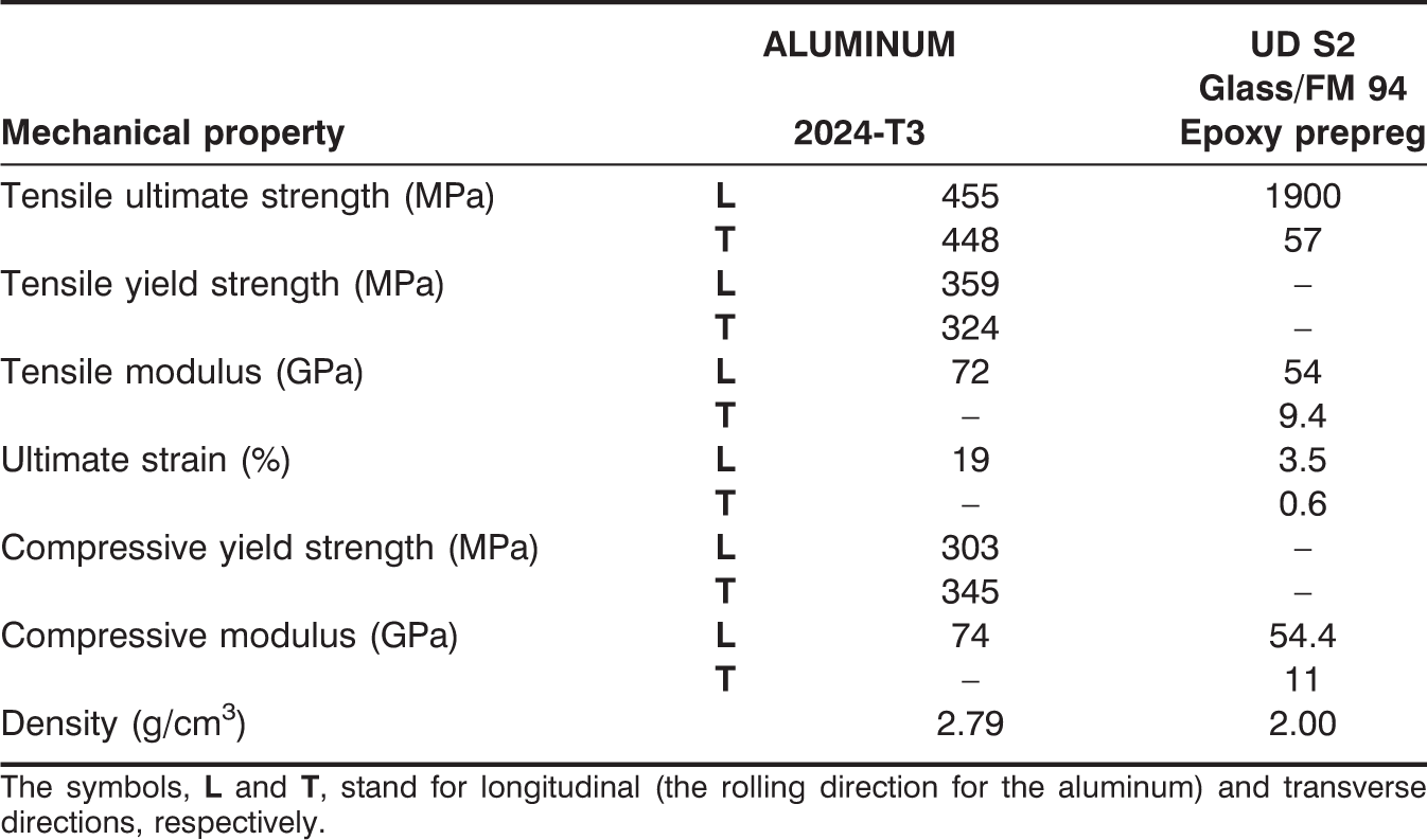
GLARE 5 is a fiber–metal laminate (FML) made of interlacing layers of 2024-T3 aluminum alloy sheets and S2-glass/epoxy laminates. Due to the combining beneficial properties of monolithic metals and fiber-reinforced composites, FMLs provide drastically improved mechanical properties compared to conventional polymer matrix composites or aluminum alloys [1,2]. One major concern with polymer-based composite materials is their response to impact events. Typically, internal damage was formed in composite laminates extending well beyond the impacted area [3], which significantly reduced the strength and stiffness of the composite. This internal delamination damage was not usually apparent on the surface of the specimen. It is thus critical that the response of the composite laminates be well understood, so that we can estimate the size of damage from a given impact [3]. On the other hand, FMLs did not show such an undesirable response. Under impact loading, they developed damage similar to both a monolithic alloy and a polymer-based composite laminate [3]. The internal impact damage in GLARE was mostly confined to a relatively small area surrounding the point of impact. Its size was always smaller than the size of the visible plastically deformed dent exposed at the outer aluminum layers for GLARE laminates [3].
Liu and Liaw [4] investigated low-velocity impact damage in ARALL 3 and various GLARE grades, i.e., GLARE 1, 2, and 3. They found that GLARE 1 with glass–epoxy prepregs possessed higher impact tolerance than ARALL 3 with aramid–epoxy prepregs. They also concluded that GLARE 3 with [0°/90°] cross-ply glass–epoxy prepregs offered better impact resistance than GLARE 2, which is made of
In this study, low-velocity impact behaviors of GLARE 5 (3/2) FMLs with various lay-up configurations and of two different shapes: square and circular, were studied experimentally using an instrumented drop-weight apparatus. Here, the notation (3/2) means three 2024-T3 aluminum alloy sheets interlace with two S2-glass/epoxy laminates, each with four plies. Impact damage characteristics were investigated based on optical images, ultrasonic C-scan, mechanical-sectioning technique and strain-gage measurements.
MATERIALS AND EXPERIMENTAL PROCEDURES

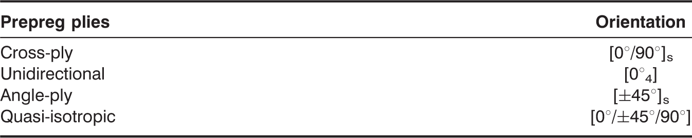
GLARE 5 (3/2) panels tested in this study with different stacking sequences.
The symbols,
All impact tests were conducted using an Instron Dynatup 8250 pneumatic-assisted, instrumented drop-weight impact tester. The specimens were clamped circumferentially along a diameter of 76.2 mm (3″) in the specimen fixture and impacted by a hemispherical steel impactor of diameter 16 mm with a mass of 6.14 kg. A pair of pneumatic breaks was used to ensure no multiple strikes during impact test. The contact force history of impact was measured using a load cell located right above the impactor nose, and the impactor velocity was recorded by a pair of photo-diodes attached to the base of the test machine. The time histories of the impactor position and the absorbed energy were obtained numerically by applying Newton's law and the energy balance principle.
In order to measure the strain outputs, two sets of strain gages were mounted on the specimens with a distance 25.4 mm (1″) away from the impact center. The locations of these two sets of strain gages are shown in Figure 1 for both geometrical shapes. The first set consists of a pair of strain gages located at 0° and 90° with respect to the 0° fiber direction in order to measure the radial and hoop strains along the 0° fiber and its transverse directions, respectively. The second set of strain gages was placed at angles of ±45° with respect to the 0° fiber direction for measuring the hoop and radial strains at ±45°.
Schematic of strain gage locations on the square and circular specimens.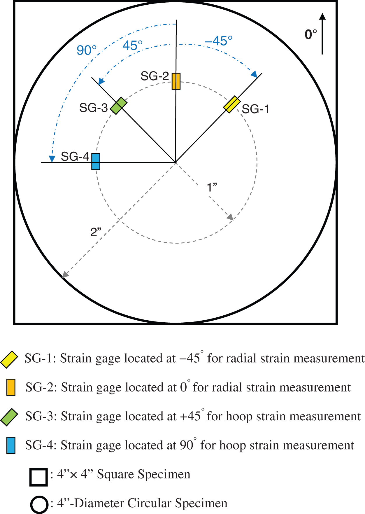
After each test, the specimen was carefully removed from the fixture for post-impact damage assessments. Figure 2 illustrates how the post-impact permanent central deflection was measured. Both nondestructive ultrasound and optical evaluation techniques were used to assess the impact damage inside the panels. The impacted specimens were scanned with an UltraPAC immersion ultrasound system for nondestructive damage evaluation. In this study, a pair of 5 MHz ultrasonic transducers (one focused and another flat) in through-transmission mode was adopted to access the damage in the impacted specimens. The scanned specimens were then carefully sectioned into two halves using a diamond blade through the impact center. Finally, cross-sectional optical pictures were taken to reveal the more detailed damage inside the specimen.
Measurement of the permanent central deflection.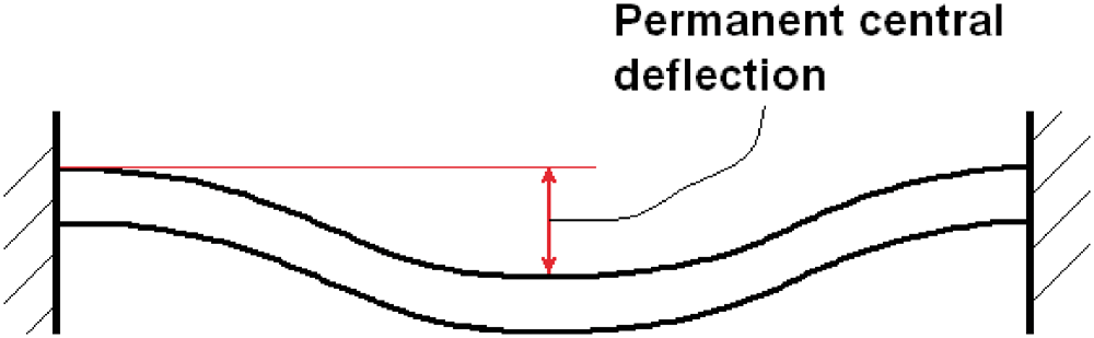
EXPERIMENTAL RESULTS AND DISCUSSION
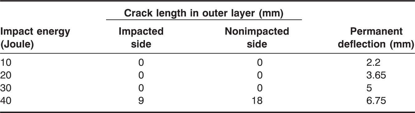
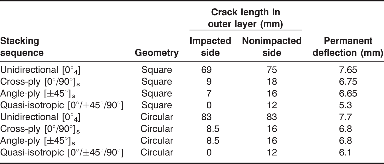
Crack lengths and permanent deflections of the cross-ply GLARE 5 (3/2) FMLs under different impact energies.
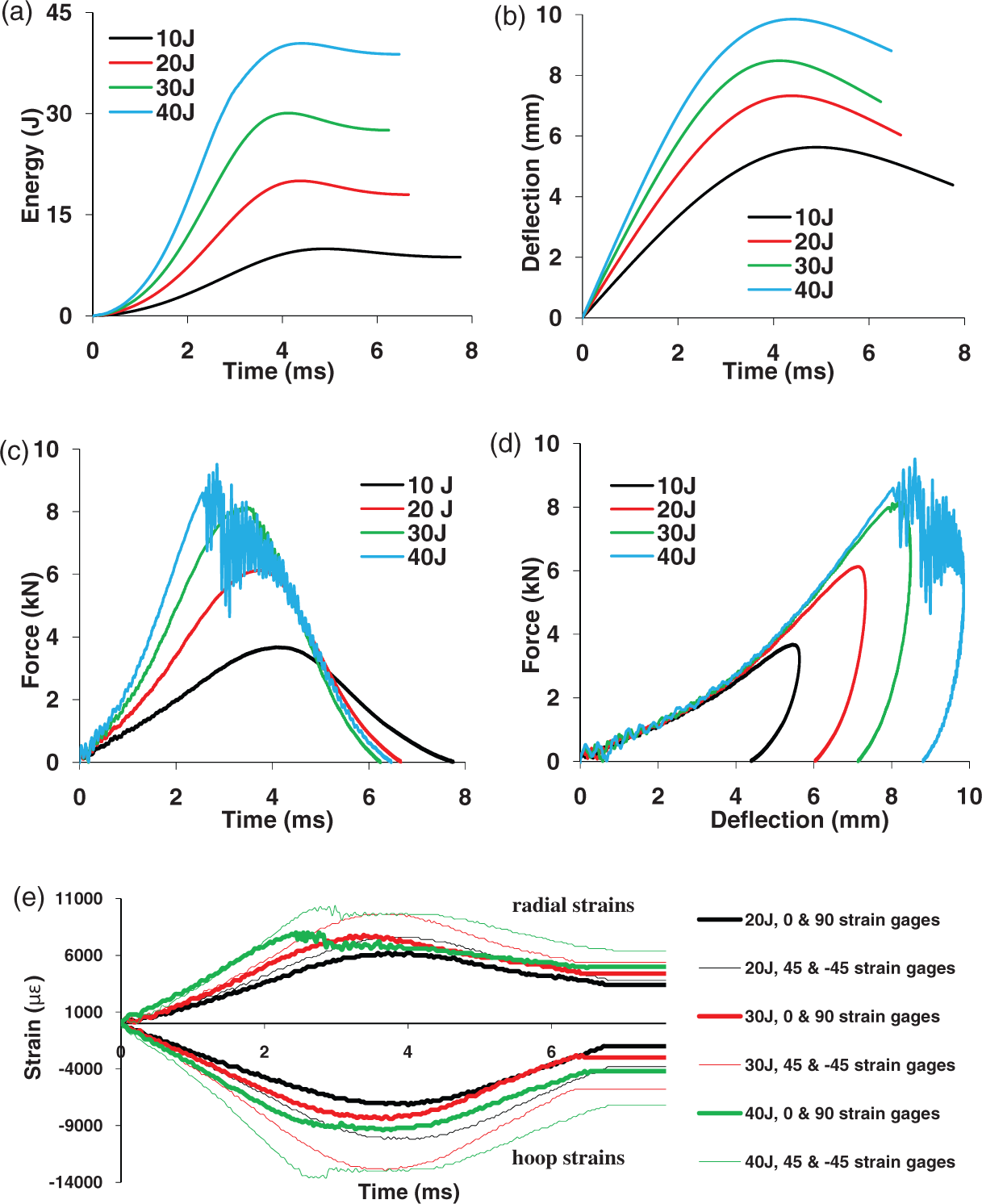
Impact responses of the cross-ply GLARE 5 (3/2) under various impact energies: (a) absorbed energy, (b) central deflection, (c) contact force, (d) contact stiffness, (e) strains.
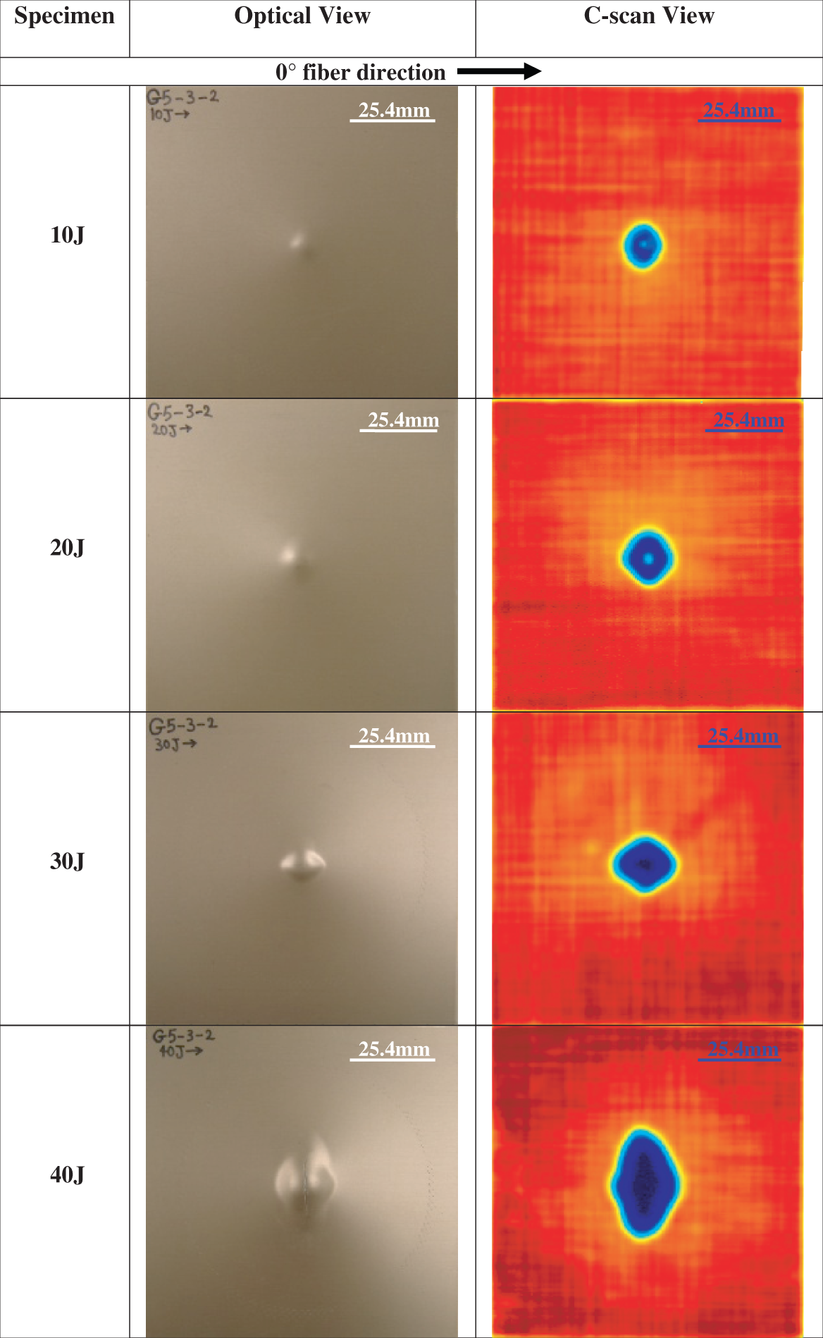
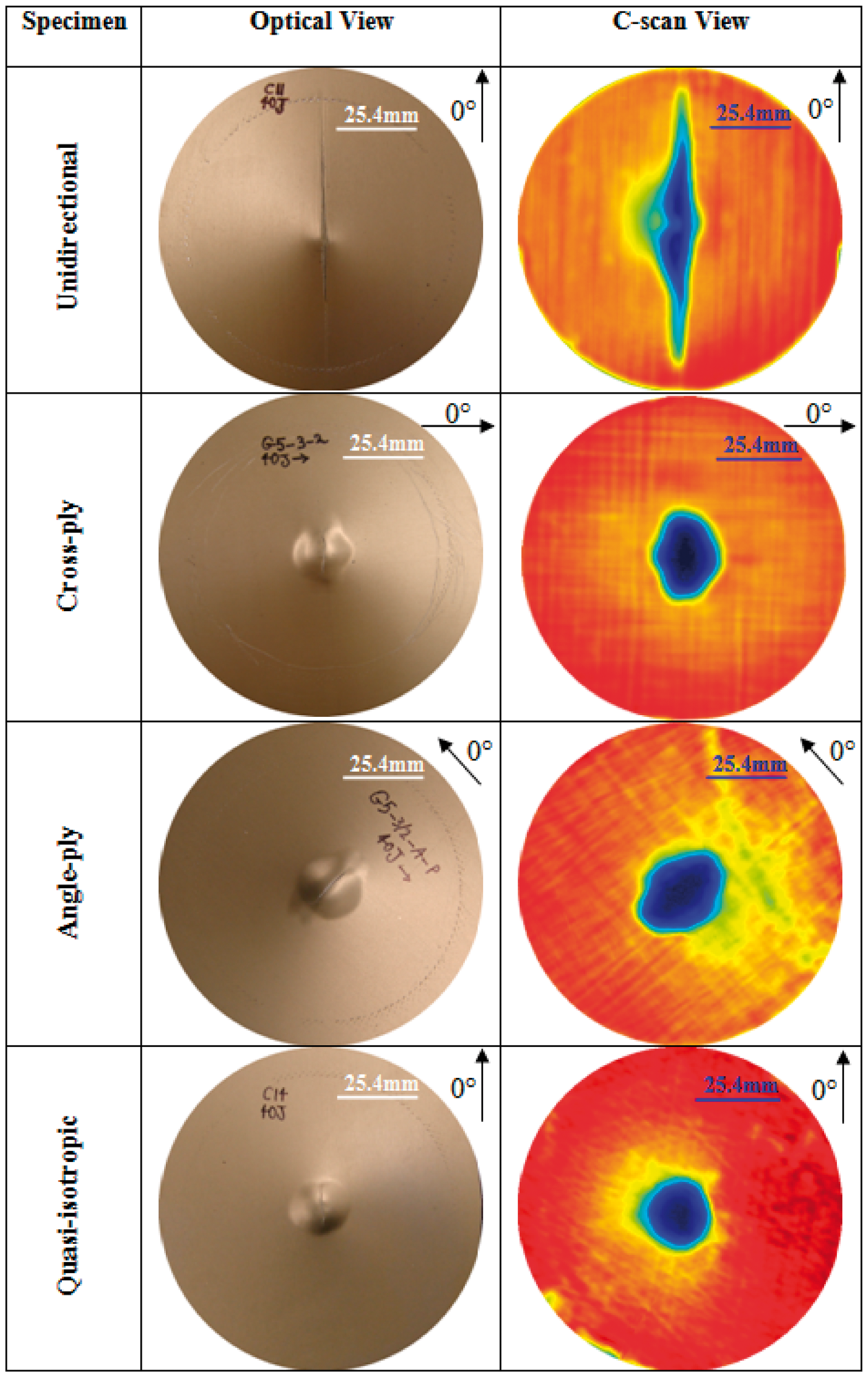
Back-side (nonimpacted) view and corresponding C-scan view of the cross-ply GLARE 5 (3/2) FMLs under various impact energies.
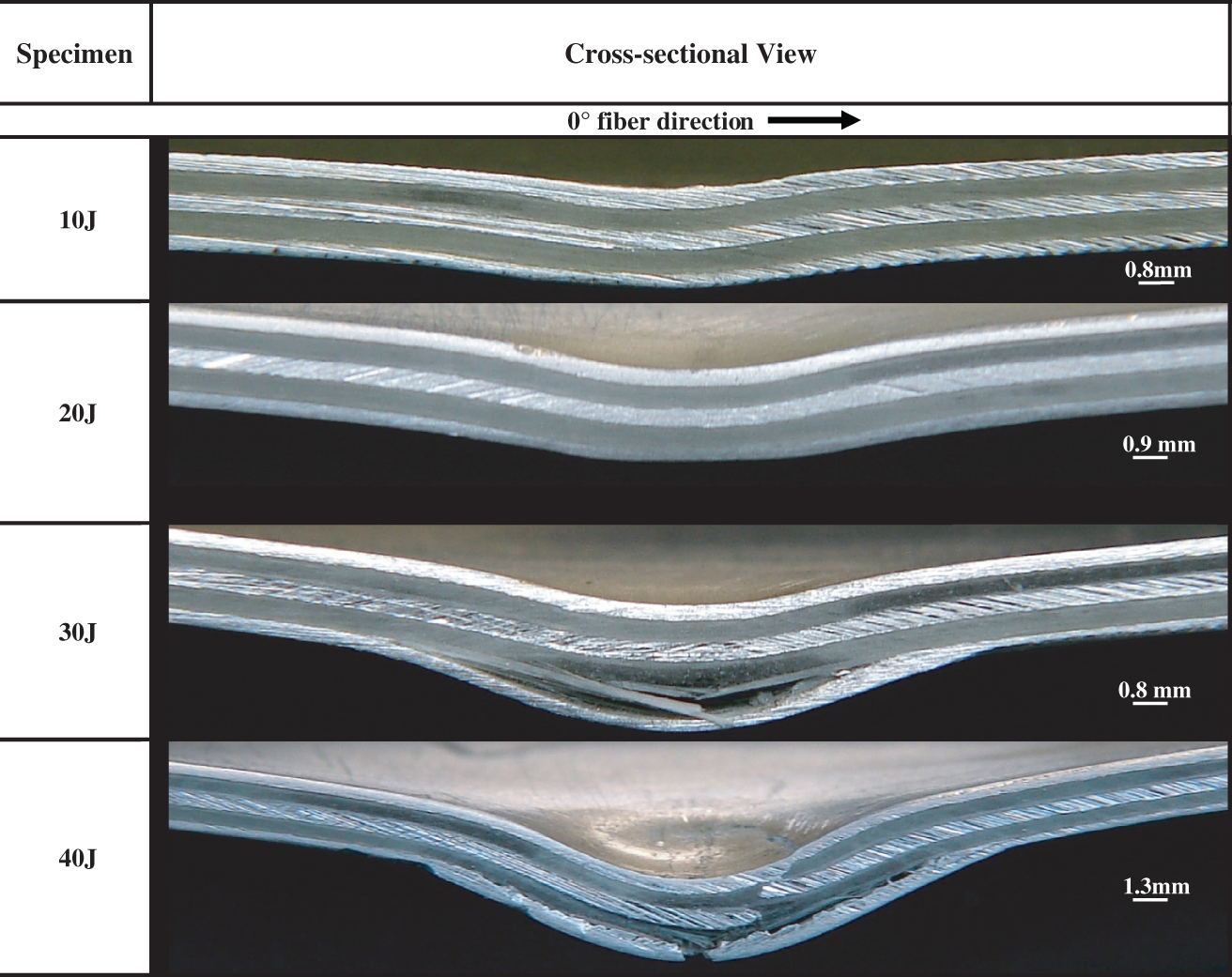
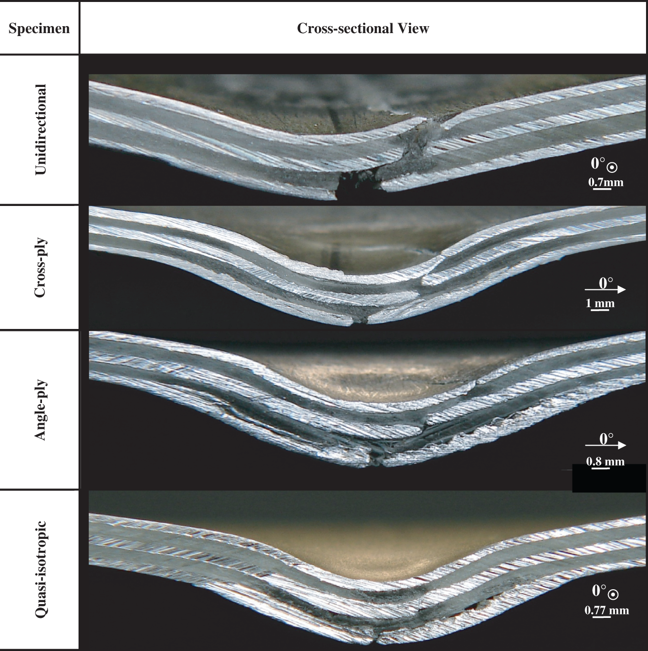
Cross-sectional view of the cross-ply GLARE 5 (3/2) FMLs under various impact energies.
For the cases of 10 and 20 J impact energies, fairly smooth contact force history and contact stiffness curves were obtained (Figure 3(c) and (d)). By referring to Figures 4 and 5 no major damage could be seen except a small indent, slightly bent of the specimen and almost invisible debonding between the lower aluminum layer and its adjacent S2-glass/epoxy laminate. There was no crack on both the impacted and nonimpacted sides (Table 3). As the impact energy further increased, oscillatory behavior could be seen in both contact-force and contact-stiffness curves. This behavior became very obvious under 40-J impact energy, indicating more damage induced in the specimen and as confirmed in Table 3, Figures 4 and 5. For the 30-J impact energy case, damages induced were fiber breakage/splitting, delamination, matrix cracking, impact indent, and permanent plastic deformation. At this impact energy, there was also no crack on either the impacted or the nonimpacted side of the specimen. By increasing the impact energy to 40 J, more pronounced damage could also be seen, including through-specimen cracks and severe delamination (Figures 4 and 5). These observations are similar to those reported in Ref. [3].
With increasing the impact energy, the resultant strains also increased (Figure 3(e)). This was because the central deflection of the panel increased (Table 3). As indicated by the initial portions of the strain histories in Figure 3(e), i.e., the time interval between 0 and 2 ms, the strain rate increased as the impact energy raised from 20 to 40 J. Based on Figure 3(e), strain results in the ±45° directions were higher than those in the 0° and 90° directions. The reason for this is believed to be the influence of the fiber direction with regard to the strain gage locations. That is, since the top aluminum layer, where the strain gages were mounted, was very thin and had a very good bonding with the adjacent prepreg layer, therefore the strains were influenced by the fiber direction. For the cross-ply Glare 5 (3/2) both 0° and 90° are fiber directions. Due to the fact that fibers can resist more to stretching, the strains along these 0°/90° fiber directions were lower in comparison with those measured at ±45°.
As shown in Figures 4 and 5, the area of the entire damage zone and local indentation increased with increasing impact energy. The presence of a small dot in the C-scan results for the cases of 10 and 20 J impact energies indicates the material at that spot did not separate. This was a direct result of the compression/compaction effect right underneath the impact site.
Because under 40-J impact energy major type of damages, i.e., fiber breakage/splitting, through-specimen crack and significant delamination, could be detected for the GLARE 5 (3/2) cross-ply panels; hence, 40-J impact energy was chosen in this investigation to study the impact responses and damage patterns of the GLARE 5 (3/2) panels with different stacking sequences.
GLARE 5 (3/2) Square Specimens with Various Lay-up Configurations
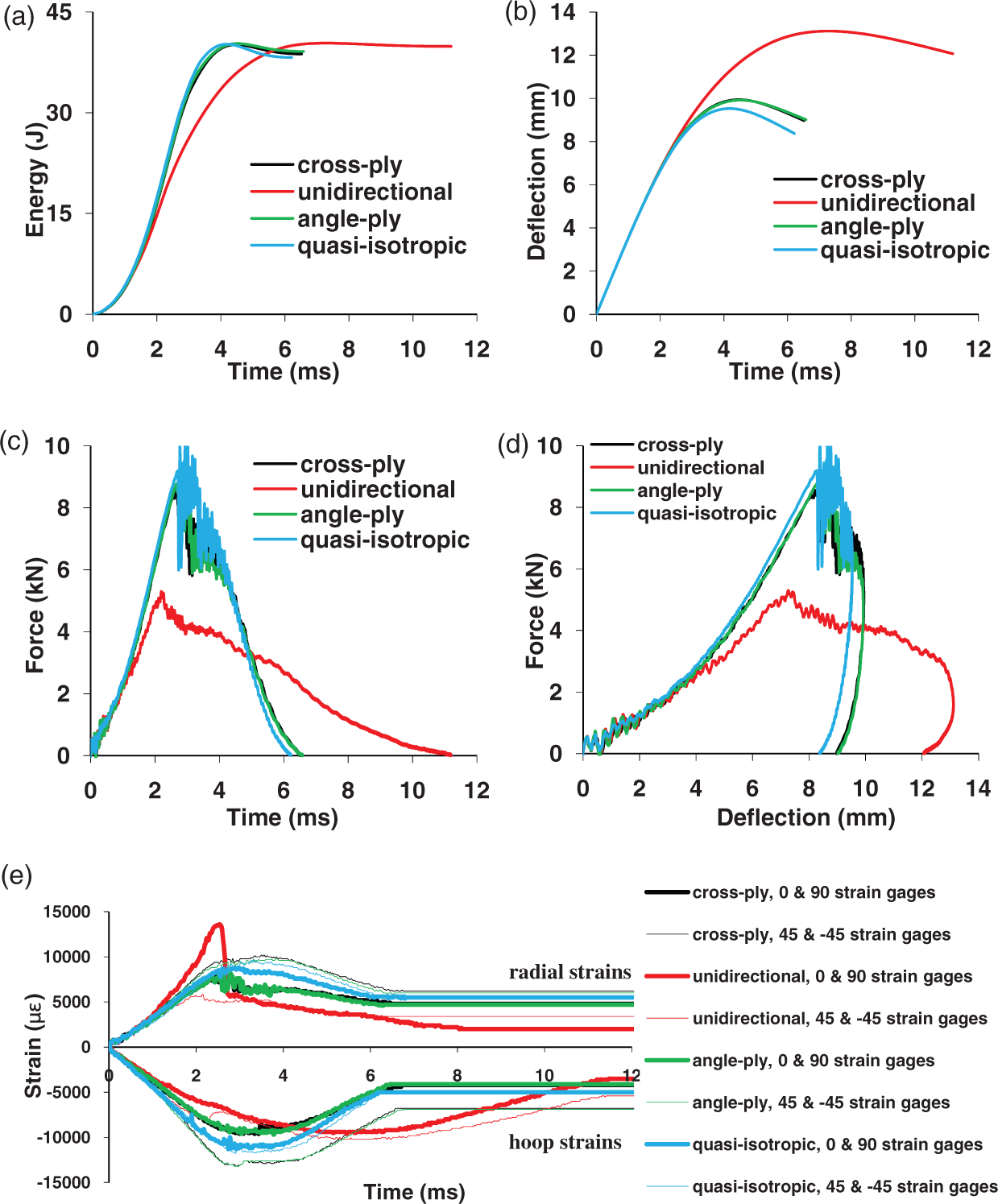
Figure 6 shows the histories of absorbed energy, central displacement, contact force, contact stiffness, and strains for the square GLARE 5 (3/2) specimens with cross-ply, unidirectional, angle-ply, and quasi-isotropic lay-up sequences. The associated C-scan results, back-side (nonimpacted) views, and the cross-sectional views are shown in Figures 7 and 8.
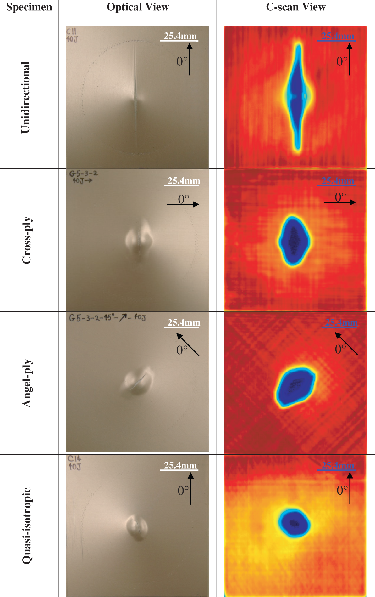
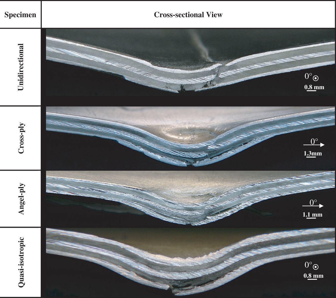
Impact responses of the GLARE 5 (3/2) square specimens with various stacking sequences under 40-J impact energy: (a) absorbed energy, (b) central deflection, (c) contact force, (d) contact stiffness, (e) strains. Back-side (nonimpacted) view and corresponding C-scan view of the GLARE 5 (3/2) square specimens with various stacking sequences under 40-J impact energy. Cross-sectional view of the GLARE 5 (3/2) square specimens with various stacking sequences under 40-J impact energy. The symbol ⊙ means that the fiber direction is out of the plane.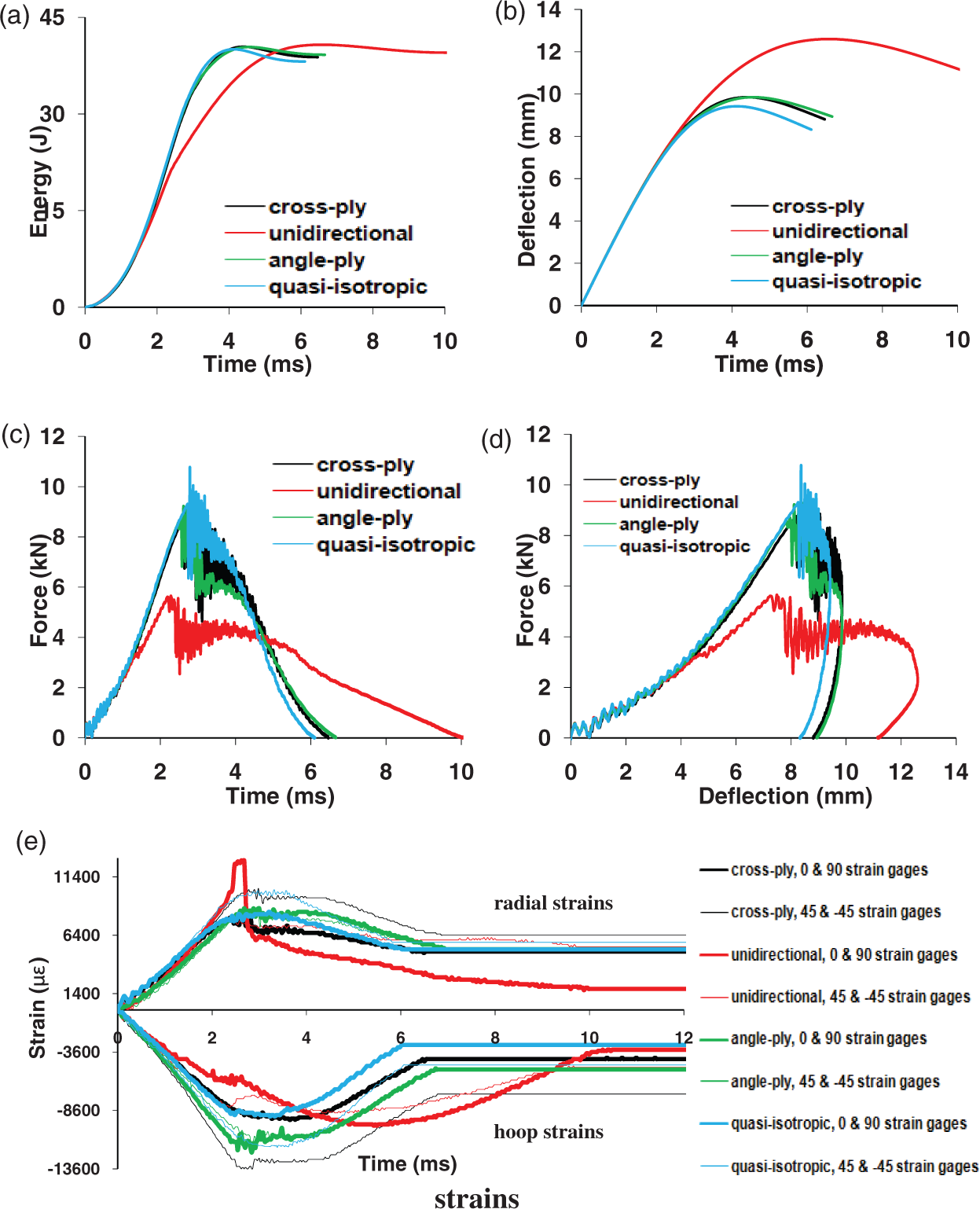
The absorbed energy history revealed that under the same impact condition, the unidirectional panel released less energy, whereas the quasi-isotropic released the most. The peak value of central deflection was the highest for the unidirectional panel while the lowest was for the quasi-isotropic. For the GLARE 5 (3/2) cross-ply and angle-ply, this peak was approximately the same. Hence, the quasi-isotropic panel offered more resistance to indentation than other types of lay-up configuration. The unidirectional panel was the worst panel to sustain the impact. By comparing the contact force histories, the unidirectional panel had the lowest peak contact force and the longest contact time duration. The quasi-isotropic panel offered the highest peak contact force among the other panel types. It is worth noting that although the contact-stiffness and the contact-force histories for the GLARE 5 (3/2) panels with cross-ply, angle-ply, and quasi-isotropic lay-up configurations were similar (Figures 6(c) and (d)), their corresponding damage patterns were quite different (Figures 7 and 8). From Figure 6(d), it could be observed that contact stiffness curves started to deviate at 4.1 mm of the central deflection, which is corresponding to contact time at 1.16 ms, Figure 6(c). Similar observation had also been reported by Liu and Liaw [4] when comparing the unidirectional GLARE 2 versus cross-ply GLARE 3.
C-scan and mechanical-sectioning results revealed that the major types of damage for the GLARE 5 (3/2) cross-ply panels were through-specimen crack, fiber breakage/splitting, and delamination (Figures 7 and 8). The major delamination occurred between the nonimpacted side aluminum layer and the adjacent glass–epoxy layer. Some smaller regional delamination around the middle aluminum layer was also found. An elliptical-shaped damage zone was induced with the major diagonal perpendicular to the 0° fiber direction. For the unidirectional panel, long visible through-the-thickness cracks extended almost to the clamped edge were generated (Figure 7). There was not much delamination besides fracture of aluminum layers and the splitting of the glass–epoxy layers for the unidirectional panel (Figure 8). Since there was no bending stiffness mismatch in a unidirectional prepreg layer, no delamination was expected in the interface of the unidirectional prepreg layer. The fracture of aluminum in the nonimpacted side resulted from bending while the stress concentration induced the crack in the impacted face. Its damage zone observed from C-scan (Figure 7) looked like a lip-shaped rhombus with the major axis aligning along the fiber direction.
The damage pattern for the angle-ply panel was very close to the cross-ply panel except for the orientation of the damage contour (Figure 7). In short, the major and minor axes of the elliptical-shaped damage zone coincided with the fiber directions. Furthermore, the major diagonal, i.e., perpendicular to the 0° fiber direction, within the elliptical-shaped damage contour was relatively shorter for the angle-ply panels compared to the cross-ply panels (Figure 7). It should be noted that by circumferentially clamping a square specimen inside the specimen fixture, the total clamping area on each face of the specimen, i.e., bottom and top, is equal to 57.62 cm2 (8.93 in.2) (57.62 cm2). Due to the stacking sequence of the angle-ply specimens, i.e., [±45°]s, with respect to the specimen geometry, there would be more fibers that were clamped compared to the cross-ply square specimens. It is believed that mainly because of this reason, the angle-ply specimens offered slightly more resistance to impact compared to the cross-ply specimens. For the quasi-isotropic panels, major types of damage, as shown in Figures 7 and 8, were crack in the nonimpacted side aluminum, damage in the bottom [0°/±45°/90°] quasi-isotropic prepreg layer as well as significant delamination between the −45° and 90° layers (due to mismatch in bending stiffness). A near circular damage zone was detected by ultrasonic C-scan for the quasi-isotropic panel. It is worth noting that at 40-J impact energy, a visible crack appeared in all specimens on the nonimpacted side. The crack was straight for the cross-ply, unidirectional, and angle-ply GLARE 5 (3/2) specimens, whereas it became curvy for the quasi-isotropic specimen (Figure 7).
As is apparent from Figure 6(e), the radial strain along the 0° fiber direction for the unidirectional panel exhibited a peak value followed by a sudden drop. The reason for this is due to the fact that the unidirectional panel experienced the most central deflection compared to other types of the panels (Figure 6(b)) and hence the strain value increased dramatically. It also cracked sooner (at around 3 ms) than other types of panels. The sudden drop was the ensuring result of the panel fracture. This crack passed underneath the location where the strain gage was mounted, causing the strain to release suddenly.
Figure 6(e) shows that the strain results in the ±45° directions were higher than 0° and 90° directions. Again, as mentioned earlier, the reason is due to the influence of the fiber direction with respect to the strain gage locations.
Based on the discussion above, GLARE 5 (3/2) of unidirectional lay-up offered the worst impact resistance, followed by cross-ply and angle-ply configurations, while the quasi-isotropic stacking sequence showed the best resistance to the impact. The reason for this is that the specimen stiffness decreased as the lay-up configuration changed from the quasi-isotropic to the unidirectional stacking sequence. This conclusion is also reported in Refs [5–7].
GLARE 5 (3/2) Circular versus Square Specimens with Various Lay-up Configurations
Crack lengths and permanent deflections of the GLARE 5 (3/2) FMLs with various stacking sequences under 40-J impact energy.
Impact responses of the GLARE 5 (3/2) circular specimens with various stacking sequences under 40-J impact energy: (a) absorbed energy, (b) central deflection, (c) contact force, (d) contact stiffness, (e) strains.
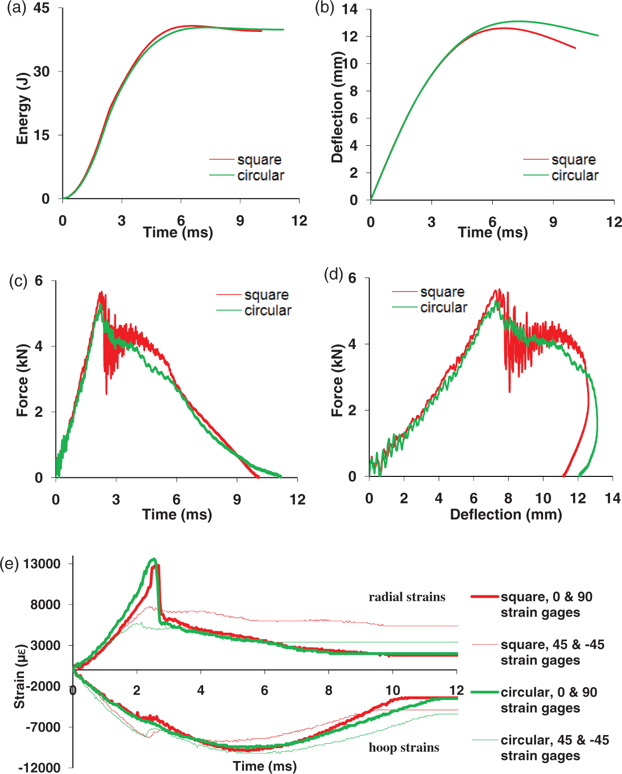
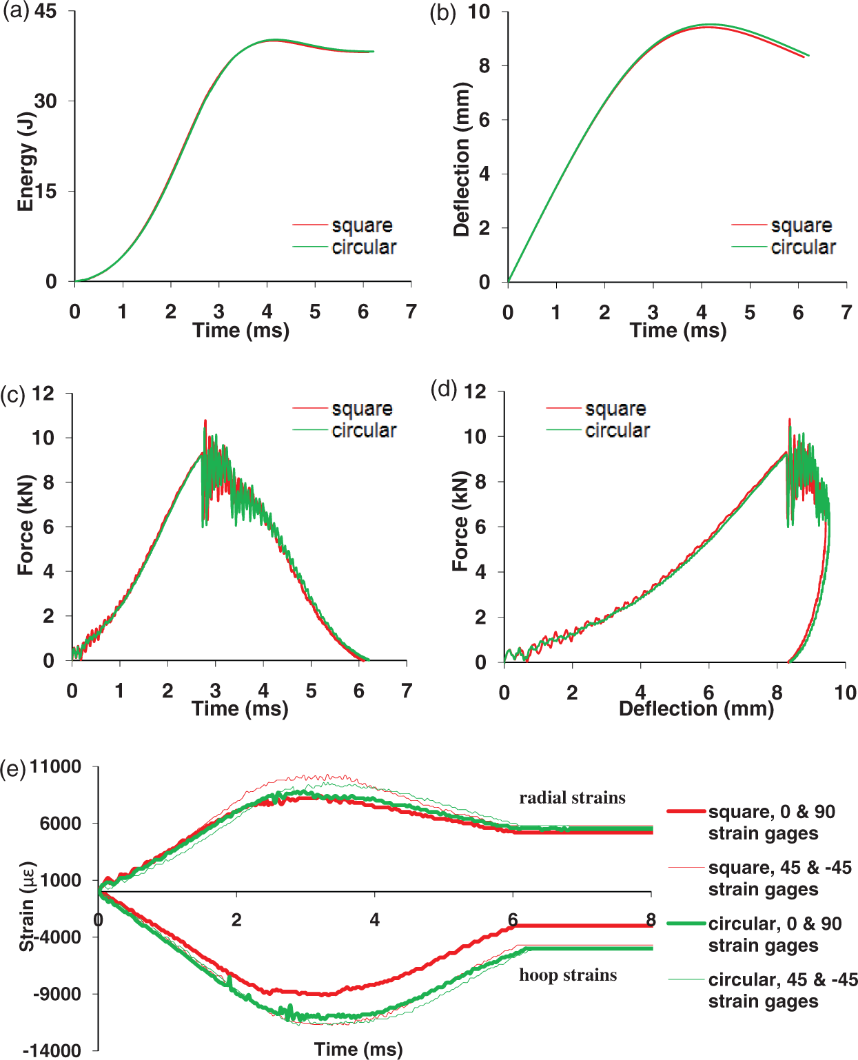
Comparison of the Impact responses between the square and circular unidirectional GLARE 5 (3/2) specimens under 40-J impact energy: (a) absorbed energy, (b) central deflection, (c) contact force, (d) contact stiffness, (e) strains.
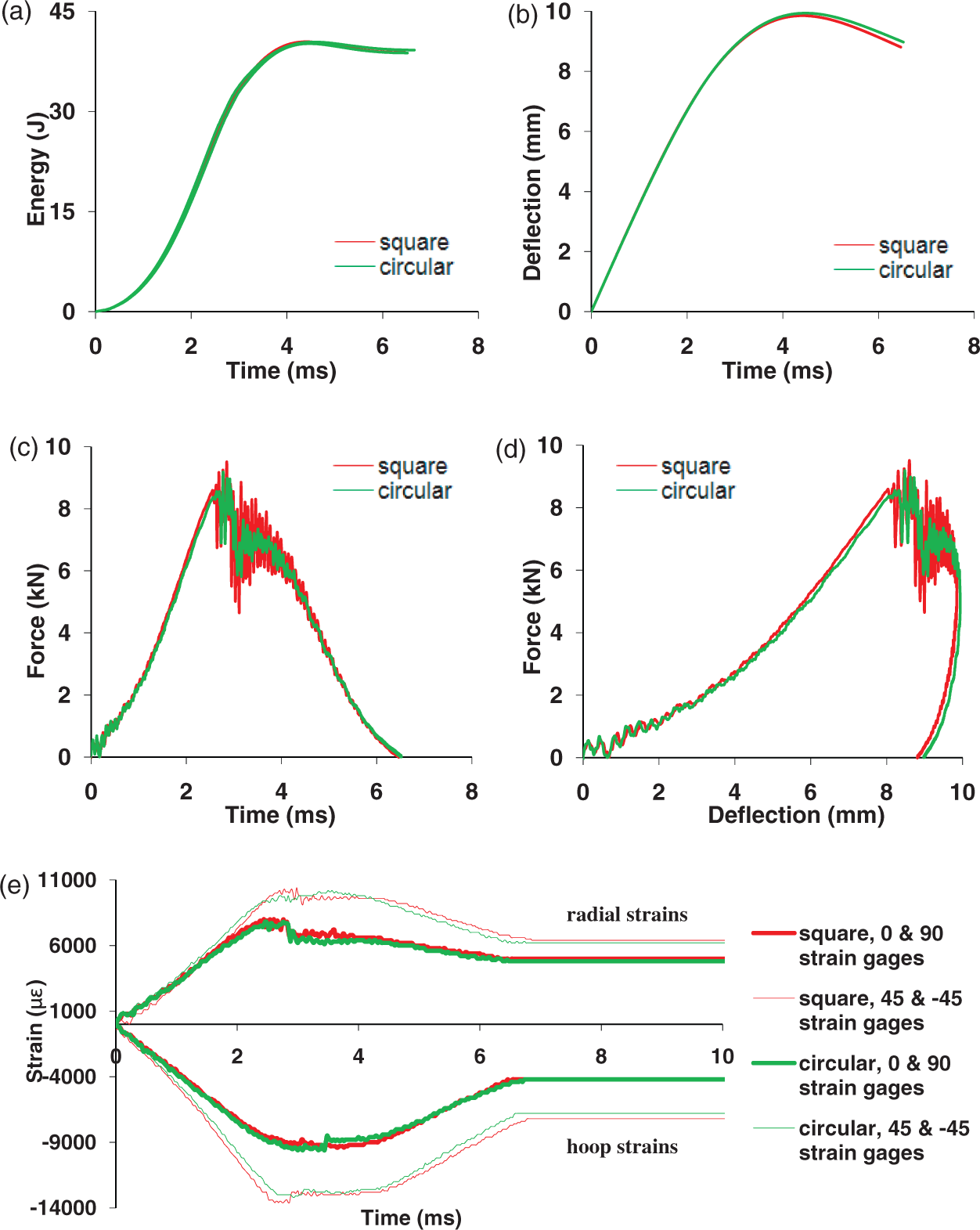
Comparison of the Impact responses between the square and circular cross-ply GLARE 5 (3/2) specimens under 40-J impact energy: (a) absorbed energy, (b) central deflection, (c) contact force, (d) contact stiffness, (e) strains.
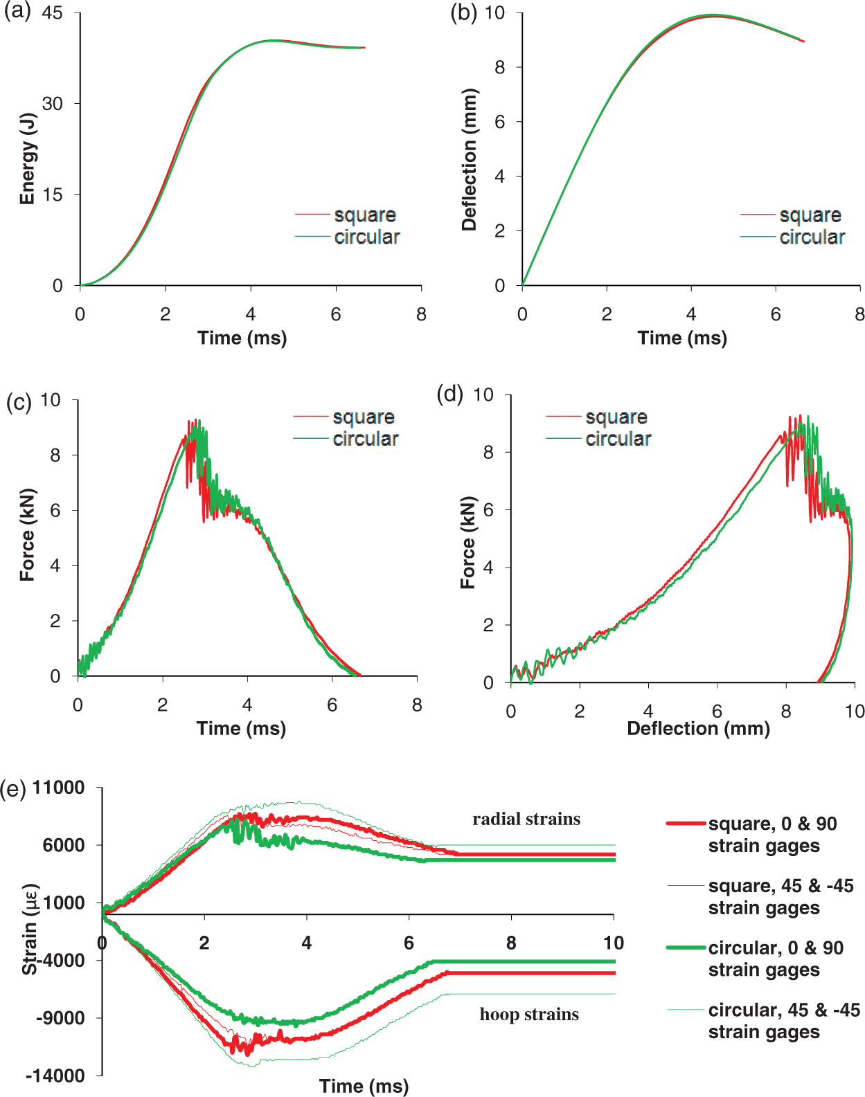
Comparison of the Impact responses between the square and circular angle-ply GLARE 5 (3/2) specimens under 40-J impact energy: (a) absorbed energy, (b) central deflection, (c) contact force, (d) contact stiffness, (e) strains.
Comparison of the Impact responses between the square and circular quasi-isotropic GLARE 5 (3/2) specimens under 40-J impact energy: (a) absorbed energy, (b) central deflection, (c) contact force, (d) contact stiffness, (e) strains.
Back side (nonimpacted) view and corresponding C-scan view of the GLARE 5 (3/2) circular specimens with various stacking sequences under 40-J impact energy.
Cross-sectional view of the GLARE 5 (3/2) circular specimens with various stacking sequences under 40-J impact energy. The symbol ⊙ means that the fiber direction is out of the plane.
The energy history curves had a pattern very close to those of the square specimens. The central deflection curves for the circular unidirectional specimens increased noticeably in comparison with the corresponding panels of square specimens. This enhancement was almost negligible for the cross-ply, angle-ply, and quasi-isotropic panels. The peak force for the unidirectional circular specimen was lower than that of the corresponding square specimen. However, for the cross-ply, angle-ply, and quasi-isotropic specimens, the difference in the peak force values was insignificant. The contact time was also raised when changing the geometry from square to circular. This difference was quite noticeable for the unidirectional panel; but it was relatively negligible for the cross-ply, angle-ply, and quasi-isotropic panels. The contact stiffness decreased by changing the geometry from square to circular. There was no significant difference in the strain results by changing the geometry. This was very apparent for the cross-ply and quasi-isotropic specimens (Figures 11 and 13). The effect of the above mentioned differences could be revealed by comparing the C-scan, back side, and cross-sectional views of the specimens with the ones for the square specimens. For the unidirectional panels of the two geometries, both C-scanned damage images were almost the same with the exception that for the circular specimen, the length of the damage along the 0° fiber direction was longer (Table 4, Figures 7 and 14). In fact, the induced crack in the unidirectional circular specimens passed the grip area of the specimen. The C-scan results revealed that the damage size decreased for the cross-ply and angle-ply circular specimens. It is apparent from Figures 7 and 14 that damage area was bigger for the quasi-isotropic circular specimen compared to its square counterpart. In addition, the circular damage shape became more rounded for the circular specimen. Based on Table 4, quasi-isotropic panels offered the minimum crack lengths in the outer layers, i.e., impacted and nonimpacted sides, as well as the least permanent deflection in their own geometrical categories.
The cross-sectional views suggested that for the circular unidirectional specimen, the induced damage pattern was different from its square counterpart. Prepreg damages among the aluminum layers were noticeably increased. Also unlike the unidirectional square specimens, in which the prepreg close to the nonimpacted side were broken into several pieces by through-the-thickness cracks, it did not happen for the circular specimen. Comparing the cross-sectional views of the two different geometries for the cross-ply specimen, the overall damage patterns were similar except in circular geometry there was no debonding between the nonimpacted aluminum and the adjacent prepreg layer. For the circular angle-ply specimen, the overall damage pattern was almost similar to the angle-ply square specimen. By evaluating the cross-sectional views for the quasi-isotropic square and circular specimens, some change in the induced damages could be seen. The bottom aluminum layer failed in a step-like mode for the square specimen, whereas there was a smooth transition for the circular specimen. Moreover, further prepreg damage was exhibited by the circular specimen. That is, by transition from square to circular geometry, the damage in the bottom prepreg composite layer, i.e., farther from the impacted face, was noticeably enhanced and extended. In addition, based on this transition, localized damage in the prepreg layers underneath the impactor was induced.
Based on the discussion above, by introducing circular, rather than square, geometry as the outer perimeter of the specimens, some differences were induced in the damage patterns as well as impact behaviors. These were due to the geometry and the relative anisotropy of the specimen with respect to the specimen clamping.
CONCLUSIONS
This study presents an experimental investigation on the impact response of GLARE 5 (3/2) with different lay-up configurations through low-velocity drop-weight tests. The following remarks can be concluded from this study.
GLARE 5 made of unidirectional fibers had the worst impact resistance; followed by cross-ply and angle-ply configurations, while the quasi-isotropic lay-up showed the best resistance to impact. The damage patterns and impact behaviors were almost invariant to the change in the specimen geometry. However, when conducting a drop-weight test using the conventional specimen geometry of a square outer perimeter and a circular inner clamp, the result will be affected by the fiber orientation of the specimen due to the relative material anisotropy with respect to the clamp fixture of the drop-weight apparatus. It is recommended that composite specimens with a circular outer perimeter and a circular inner clamp should be used instead to avoid the problem. The damage stages along with the increase of the impact energies are as follows: at lower energy impact, only delamination was induced between aluminum layer and fiber–epoxy layer near the nonimpacted side; the nonimpact side aluminum then fractured in accompany with delamination inside; finally, through-thickness cracks occurred under higher energy impact. Only the profile of damage zone could be detected through the ultrasonic C-scan. The mechanical-sectioning technique needs to be adopted to reveal the details of damage inside the FMLs. The drop-weight induced damage included indentation around impact center, delamination between aluminum and glass–epoxy composite, cracks in aluminum layers, and damage in composite layers. More severe damage occurred on the nonimpacted side of FMLs.
Footnotes
ACKNOWLEDGMENTS
This study was sponsored by NASA Faculty Award for Research (FAR) under Grant No. NAG3-2259 and by PSC-CUNY under Grants 61368-00 39 and 62209-00 40. Dr Kenneth J. Bowles and Dr John P. Gyekenyesi were the technical monitors of the NASA grant. Part of the equipment used in this investigation was acquired through Army Research Office Grant No. DAAD19-99-1-0366.