
Abstract
Ultra-high molecular weight polyethylene fibre is popularly used in military for ballistic protection owing to its low density but high modulus and high tenacity. However, the inter-yarn friction in the corresponding ballistic fabric is too low and thus the yarns in the fabric are easily pulled out, in which lowers down the ballistic performance. This paper aims to improve the inter-yarn friction in the fabric by sol-gel method using TiO2/ZnO hydro-sols and investigate the ballistic performance of fabric treated. The results from the coefficient of friction test have showed that the inter-yarn friction treated with TiO2/ZnO hydro-sol can be increased 40%. Moreover, tensile test indicates that the tenacities of yarns after different treatments are increased whereas the strains and moduli of the yarns almost kept unaffected. Through ballistic performance test, the treated fabric displays higher ballistic energy absorption compared with the original one, indicating that higher inter-yarn friction is beneficial to fabric against ballistic impact.
Keywords
Introduction
Ultra-high molecular weight polyethylene (UHMWPE) yarns are advantageous in light ballistic fabric application because of their high strength and high modulus and also the light weight. For a ballistic fabric made from such yarns, parameters including the mechanical properties, fabric pattern, yarn crimp, inter-yarn friction, multi-layer interaction, and so on are of importance to dissipate the impact energy during a ballistic event [1]. In the past decades, designers and researchers devoted themselves to balancing those parameters posed by weight, thickness and the ballistic performance, and made some progresses. With the continuous development of the fabric armour system, researchers are gradually aware of that inter-yarn friction plays a significant role in the entire fabric armour system because of the dual functions of increasing fabric absorbing the kinetic energy of the projectile and preventing slippage of primary yarns at impact centre [2–17]. Nevertheless, friction between UHMWPE yarns is much smaller, with coefficient of friction approximately around 0.1 [2], which, would lead to lower energy absorption by the whole fabric panel system. In this way, improving yarn-yarn friction for polyethylene-based materials without degrading the mechanical properties is quite meaningful to develop light soft body armour.
Friction is highly relevant to the morphology of a substance and analogically inter-yarn friction should be more associated with the morphology of a fibre. The rougher the fibre surface it is, the larger inter-yarn friction would be. Coating is an effective approach to introduce some differences to the surface of a fibre and thus influence the inter-yarn friction. Sun and Chen [13] proposed a method of plasma enhanced chemical vapour deposition (PCVD) to coat aramid yarns and found that the surfaces of yarns become much rougher and the inter-yarn friction is increased dramatically after that treatment. Furthermore, the inter-yarn friction after PCVD treatment will increase with the increase of treatment time [18]. Nevertheless, the cost of PCVD treatment is expensive because of using special PCVD treatment equipment. More economic coating methods should be developed.
Sol–gel technology is a frequently used method for general surface coating and it is able to introduce coatings to the yarn surface to modify the surface morphology of the yarn [19,20]. This method has the advantage of convenience in application and is suitable for batch processing. The attractive feature of this approach is that it can easily introduce the metallic oxide with higher coefficient of friction to the surface of the fibre [21] and this action is just acted on the upper outside of the fibre. In this way, the mechanical properties of yarns would not be affected. Also, through the sol–gel process, the oxides introduced are in the nano size or micro scale. Therefore, the weight addition would be less. In the previous investigation [21], sol–gel technology is adopted to increase the aramid fibre surface roughness and the inter-yarn friction can be improved by over 50%. The purpose of this paper is to modify the inter-yarn friction of UHMWPE fibres using sol–gel technology. TiO2/ZnO hydrosol formed by hydrolysis reaction of precursors of tetrabutyl titanate and zinc acetated will be used to coat UHMWPE yarns. The inter-yarn friction will be tested by Capstan method. The coating effects on the yarns will be discussed mainly from morphology change, coefficient of friction, weight change and tensile properties. The ballistic performance of UHMWPE fabric with several levels of inter-yarn friction will be analysed by FE method. It is anticipated that the results from this research will provide new information for treating ballistic fabrics.
Experiments and FE modeling
Experiments
Materials
The chemicals including tetrabutyl titanate Ti(OC4H9)4, ethanol, ethanolamine and zinc acetate dehydrate were all supplied by Sigma–Aldrich, and the acetic acid by Fisher Scientific. Deionized water was used for the hydrolysis of titanium (IV) butoxide and for preparation of sol–gel solution. All the chemical regents were used as received. The UHMWPE yarns used is Dyneema® yarns offered by DSM Company without any further cleaning and the linear density of the yarn is 176 tex.
Tio2/ZnO hydrosols preparation and treatment conditions
TiO2/ZnO hydrosol is prepared by mixing TiO2 hydrosol with ZnO hydrosol. The preparation process is described in detail in the previous investigation [19,20]. TiO2/ZnO hydrosols are started from creating ZnO hydrosol using the peptisation method through adding ethanolamine as the initiating materials into the mixure aqueous solution of zinc acetate dehydrates and ethanol. The mole ratio between zinc acetate dehydrate and ethanolamine was 1:1. Acetic acid was used as the peptiser for producing ZnO hydrosol. The second step in this process was to create the mixture of titanium (IV) butoxide and dehydrate alcohol with an optimal amount of glacial acetic acid. The preparation of TiO2/ZnO sol-gel is shown in Figure 1. This product was then dropped into ZnO hydrosol. After a 2-hour vigorous stirring, the compound TiO2/ZnO hydrosol was obtained. The mole ratio of Ti:Zn is 1:1. The TiO2/ZnO hydrosols were applied on the Dyneema® yarns using the Dip-Pad-Dry and Dip-Pad-Dry-Cure method. The Dyneema® yarns were impregnated with the corresponding sol solution, and were squeezed by applying a two-roll laboratory padder (CH-8155 Mathis AG, Switzerland; air pressure 3 bar, rotatory speed 2 m/min) before drying and then being cured on a curing machine (Mathis AG, Switzerland). In the treatment process, the concentration for the two types of TiO2/ZnO hydrosol used for yarn treatment is 0.2 mol/L, and the drying temperature is set to be 70 °C with drying time set as 1 min. The curing temperature for the yarn is set to be 110 °C and the curing time is set to be 1.5 min. The size of the particle in the hydrosol made at the low temperature (5 °C) is in the nano-scale and that made at the temperature (60 °C) is in the submicro-scale [19,20]. The treatments are listed in Table 1. The letter T and W represents the nano scale hydrosol and the submicro scale hydrosol, respectively. The other letters D and C in the sequence correspondingly represent for dry and cure. The yarns were put in a baker with sol–gel liquid for about 10 mins and subject to two dip-pad processes. The wet pick-ups averaged from 10 data for nano-size hydrosol and submicro-size hydrosol are 51.5% and 49.1%, respectively, shown in Table 2.

The preparation TiO2/ZnO sol–gel.
The treatments for UHMWPE yarns.

The pick-up of Dyneema® yarns.


The coefficient of friction test.
Characterization and tests
The FTIR spectra were taken using the NICOLET 5700 FTIR by Thermo Electron Corporation. An ultra-thin layer of gold is needed to coat on each specimen in the JEQ JFC-1600 coating system to make the fibre more electrically conductive for the SEM observation. EDX was employed to analyse the chemical component deposited on the surface of the fibre.
The device used for coefficients of friction test as well as how to compute the two types of coefficients of friction from the test results can refer to the description in our previous paper [18,21]. The final result is averaged from 30 samples. The method applied here is the capstan method in the case of yarn-yarn angle at 90°. In the setup, two rods with diameters of 13 mm are fixed horizontally on a frame, mounted on the tensile machine. The yarn wraps the rods in the axial direction. The displacement of the crosshead is limited to 20 mm. All the tests were carried out on Instron 5500 at room temperature of 23 °C and humidity of 50%. The illustration of coefficients of friction test and the devices are shown in Figure 2.
The tensile strength was obtained using Instron-44. 30 specimens were tested for each treatment group. In order to effectively detect the weak weight difference after different treatment conditions, the length of the sample is 3 m for the cases without curing process and 5 m for these with curing process. The test was conducted in the laboratory with temperature of 7 °C and relative humidity of 23%. The weight adding percentage R% can be calculated from equation (1), as shown in equation (1). W0 is the dry weight of sample after treatment and Wd is the weight of sample after corresponding treatment. Ten samples were used for each treatment condition group.

Ballistic test
The ballistic impact test was conducted on the ballistic range described in Figure 3. A square sample with the size of 24 cm by 24 cm is placed on an underframe with an aperture, of which the diameter is 15 cm. The speed of the projectile is around 475 m/s. The surface of the sample is covered with a square steel frame with an aperture the same as that in the underframe. The four sides of the sample are pressed under the four strip steel blocks. Each side is fixed by the tension between the steel strip block and the steel square block. The steel square blocks with two distributed in each side are tightly screwed to give enough force to fix the steel square block and the steel strip block. The four angles of the aperture are also tightly screwed. The effective area left in the sample is a circle with the diameter of 15 cm. The energy absorption of the fabric is computed from the impact velocity and the residual velocity.

The ballistic test equipment (a) The ballistic impact device, (b) the clamp condition.

The images and FE modelling of Dyneema® fabric (a) and (b) cross-section under optical microscope (c) a quarter fabric (d) Mesh image of Dyneema® fabric with projectile.
FE modeling
The fabric is plain pattern with the above Dyneema® yarns. The warp density is 7 ends/cm and the weft density is 6 ends/cm. The areal density is 242.39 g/m2. To observe the cross-section image of the fabric, a square fabric sample was positioned in a plastic box vertically and then solidified and hardened by resins and hardeners for 24 h. Next the fabric sample was taken out and the cross-section of it will be kept on polishing with sandpapers until it is clear under microscope observation. The mirco-image of the cross-section from optical microscope is shown in Figure 4(a) and (b). Based on the investigation, it was observed that the yarn cross section can be realistically represented by lenticular model and the yarn profiles are constructed with two arcs. The thickness of the fabric is 0.484 mm. The wavelength in the warp direction for the Dyneema fabric is 3.296 mm and 2.804 mm for the weft direction. The width of the single yarn in the Dyneema fabric is about 1.082 mm in the warp direction and 1.308 mm in the weft direction. The modeled fabric and projectile can refer to Figure 4(c) and (d).The mechanical properties are shown in Table 3. A simple geometry of packing creates a tightest volume ratio of 0.70, leading to
The mechanical properties of original Dyneema® yarn [22],[23].


The FTIR spectra of Dyneema® yarns treated by TiO2/ZnO hydrosols.
Results and discussions
Characterization
The FTIR data in Figure 5 associated with EDX analysis in Table 4 of the prepared samples are used to identify the products on the fibre. The typical absorption peaks for the original Dyneema® yarn have been discussed in Reference [24]. All the spectra of the Dyneema® yarns treated by TiO2/ZnO hydrosols share the same characteristic in Figure 5. After treatments, several new absorption peaks appear on the spectra. In the high wave number spectral range, a broad band between wave frequency 3600 and 3100 cm−1 is assigned to fundamental stretching vibrations of different hydroxyl groups (free or bounded) [25]. The peak at 1400 cm−1 is attributed to the vibration mode of Ti–O bond [26]. The band at 620 cm−1 is assigned to Ti-O-Zn bond [25] and the band at 470 cm−1 is ascribed to Ti-O-Ti bond by condensation reaction [27–29]. As such, the substances coated on the Dyneema® yarns with different particle sizes of TiO2/ZnO hydrosols are similar and they are TiO2/ZnO compounds. Table 4 lists the elements on the surfaces of the Dyneema® yarns treated by TiO2/ZnO hydrosols and it corroborates that the surfaces of those yarns have been covered with element Ti and Zn. The existence of oxygen in the original Dyneema® yarn is probably formed during the production of UHMWPE fibre [30,31].
The components of the elements (atomic %) on Dyneema® yarns with TiO2/ZnO hydrosols.


The morphology images of Dyneema® yarns by sol–gel treatments (a) Original; (b) TiZn-WD (micro-size); (c) TiZn-WDC((micro-size; (d) TiZn-TD(nano-size); (e) TiZn-TDC(nano-size).

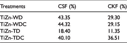
The coefficients of friction for Dyneema® yarns at different sol–gel treatment conditions.
It should be pointed out that the peaks around 1114 cm−1, 955 cm−1, 930 cm−1 are attributed to the precursors or species derived from them [25]. It is known that the absorption bands in the range 1100–1000 cm−1 are attributed to the OR groups linked to Ti such as OC2H5, OC3H7 and OC4H7. The characteristic absorption peak of (OR) group of titanium isopropoxide, which is the structure contained in the precursors of the sols, is in the range of 1085–1050 cm−1 [32]. 1560 cm−1 and 1339 cm−1 may be caused by the reaction substance containing N-H and C-N deformation couple modes. These absorption peaks are not detected on the Twaron® yarns because they may be overlapped with absorption peaks of some groups built in the Twaron® chemical structure.
Further, SEM images are obtained to reveal the morphology change of Dyneema® fibre before and after deposition of TiO2/ZnO gel. The morphologies of the treated and the untreated Dyneema® yarns are shown in Figure 6. The surface of the original Dyneema® yarn is not as smooth as other synthetic fibres. The striations are clearly revealed on fibre surface [33]. In addition, along the longitudinal direction, bamboo-like joint is shown in the micrograph of the original Dyneema® yarn. Compared to the original Dyneema® yarns, the texture of the coating through gelification of larger particle size is larger, thicker, more irregular while the smaller size particle form a thin layer on the fibre surface. Regarding the coating morphology of the Dyneema® yarns subjected to different thermal treatment histories in the same hydrosol group, further higher temperature heating plays a role in the continuity of the coating texture. The higher temperature causes more gelification to take place and more liquid entrapped in the gel to evaporate. In this way, the coatings on the fibre with curing process are more discontinuous, as shown in Figure 3(c) and (e). Generally, the larger size particle in the sol would form more granular-like coating and the smaller size particle sol would give rise to a film-like appearance.
The coefficient of friction
The coefficients of friction for Dyneema® yarns after sol–gel treatments are shown in Figure 7. The CSF(coefficient of static friction) and CKF(coefficient of kinetic friction) values of the treated Dyneema® yarns given below display different degrees of increase compared with the values of the original yarn. All the data are tested statistically at the confidence significance interval of 95% and the P value is smaller than 0.05, which means the change is significant. The increase percentage for each case is shown in Table 5. On the whole, the CSF and CKF of Dyneema® yarns treated by TiZn-WD, TiZn-WDC and TiZn-TDC can be increased by approximately 40% and 30%, respectively. Nevertheless, the CSF and CKF of those yarns treated by TiZn-TD only shows 20% and 10% increase with respect to the original yarns. The effects of TiO2/ZnO hydrosol treatment on the coefficients of friction are largely attributed to surface changes of those yarns. As shown in SEM images (Figure 6), the surfaces of the yarns treated with TiZn-WD, TiZn-WDC become much rougher and the yarn surface treated with TiZn-TDC goes into uneven because of the gel contraction. Nevertheless, the yarns treated with TiZn-TD seem to be covered with a layer of film, which inversely in a certain degree decreases the roughness of the surface. Through proper control of the TiO2/ZnO hydrosol treatment process parameters, the coefficients of friction of UHMWPE yarns can be increased. It should be mentioned here that in the previous investigation, sol–gel technology is adopted to increase the Twaron® fibre surface roughness, the inter-yarn friction can be improved by over 50%. However, for the current Dyneema® yarns it is indicated by 40%. The differentiation may be due to the varied original fibre surface morphology. For the Twaron® fibre, the surface of it is smooth but the surface of the Dyneema® fibre is with striation. The smooth surface of Twaron® fibre is easily roughened but the coatings may be filled in the crevice on the Dyneema® fibres.
The increasing percentages of CKF and CSF of Dyneema® yarns after sol–gel treatments.
Weight add-on
The increasing percentages for all cases are given below in Table 6. All the data are experienced significant test at 95% confidence interval and it is smaller than 0.05 and is reliable. For the Dyneema® yarns, the surface of it is inert owing to the less functional groups in its structure [33]. Therefore, there is no weight loss due to the acid and relatively higher temperature action. Generally, all the yarn weights are increased after the treatment because new materials have been introduced onto the yarn surface. In addition, in Table 6, it is also found that the treatments with curing process results in less weight increase of the yarn than the corresponding treatment without curing process. As mentioned before, the curing process is a process to further densify the gel, causing the liquid in the gel to further evaporate and leading to less increase of weight. Therefore, curing process is necessary when light weight of treated yarn for ballistic application is required.
Weight changes of yarns in different sol-gel treatment conditions.


The change of Dyneema® yarn tensile properties after treatments. (a) Change of tenacity; (b) change of Modulus; (c) change of tenacity.
Tensile properties
The changes of tensile properties are shown in Figure 8 and the change percentages after treatments are given in Table 7. The change significance of the tensile properties of Dyneema® yarns caused by sol–gel treatments are also evaluated by the statistical significance test at 95% confidence interval. All the P value is smaller than 0.05, indicating that the change is significant. It is interesting to observe that all the treatments lead to the increase of yarn tenacity but the decreases of yarn modulus and strain. The increase in tenacity after the treatments may be owing to the inert property of Dyneema® yarns and the increased friction between filaments. The decrease in modulus and strain may be associated with the poor heat resistance property of the Dyneema® yarns. In addition, the increase of tenacity in the group of submicro-scale is larger than that in the nano- scale. For the modulus, the group of submicro-scale treatments bring less effect than the group of nano-scale treatments. The decrease in strain after the four treatments is equal and is around 5%.
The change percentages of tensile properties for treated Dyneema® yarns.

The ballistic impact
From above analyses, the sol–gel method is one of the effective methods to increase the inter-yarn friction. Due to the technical problems, the yarns treated with sol–gel can not be woven into a fabric where the yarns would experience heavy rub with heddle on the heald frame during the weaving process and the coatings on the yarns could be damaged. In this way, one of the sol–gel treatment, TiZn-TDC was applied to treat the corresponding Dyneema® fabric. TiZn-TDC treatment is selected because from tensile properties and weight analyses, the tenacity of yarns treated with it is almost not changed and the Young’s modulus and strain is reduced, and also its weight increase is minimal.
The energy absorption of single-layer treated and untreated Dyneema® fabrics impacted by a one-gram cylinder projectile is shown in Figure 9. From the results in Figure 9, the energy absorption of fabric treated with TiZn-TDC is higher than the original one, about 7.84% in average, indicating that increasing inter-yarn friction indeed will improve the ballistic performance. In view of the small increase of weight, the normalized energy absorption is shown in Figure 10. From the results in Figure 10, the normalized energy absorption of fabric treated with TiZn-TDC is higher than the original one, about 9.66% in average, indicating that increasing inter-yarn friction indeed will improve the ballistic performance. Figure 11 shows the time history curves of the loss of the projectile kinetic energy at different frictional conditions with FE analyses. The loss of the projectile kinetic energy is theoretically equivalent to the overall energy absorption of fabric. In the frictional range from zero friction to CSF of 0.6 and CKF of 0.55, higher inter-yarn friction always gives rise to higher overall energy absorption since it will speed up energy absorption of fabrics [34]. In addition, the inter-yarn friction obtained from sol–gel-treatment is far from getting highest energy absorption. Therefore, new method to further increase the inter-yarn friction needs to be developed.

The energy absorption of the fabrics during ballistic impact.

The normalized energy absorption of the fabrics during ballistic impact.

The loss of projectile of kinetic energy as function of time at different frictional levels.
Conclusion
The sol–gel technology applied to coat the yarn is a novel attempt to increase the inter-yarn friction in fabrics for ballistic protection. Two types of TiO2/ZnO compound hydrosols, the submicro-scale one and the nano-scale one obtained by controlling the reaction temperature, have been applied to coat one of the UHMWPE yarns, Dyneema® yarns with and without curing process with the purpose of changing the morphology of the yarns, achieving increase of inter-yarn friction. SEM images have showed that the surface of the yarns treated with TiO2/ZnO submicro-scale hydrosol is covered with lump-like substance whilst that in case of TiO2/ZnO nano-scale hydrosol is covered with film-like substance. FTIR and EDX analysis have confirmed that the coating substance is titanium dioxide and zinc oxide. The results from the coefficient of friction test have showed that the inter-yarn friction treated with TiO2/ZnO hydrosol can be increased 40%. Moreover, the tensile test indicates that the reduction in tenacity of the yarn after different treatments is increased whereas the strain and modulus of the yarn after treatments are decreased. The decrease of strain and modulus of the yarn is lower than 7%. The weight increase after treatment is lower than 10%.
This research has proved that the sol–gel method is a feasible and valid method to increase inter-yarn friction for Dyneema® yarns at the same time almost without affecting the weight and tensile properties of the yarn. Furthermore, the ballistic test approved that the fabric with higher inter-yarn friction are better at energy absorption in the ballistic impact process. Through FE simulation, however, we found that the inter-yarn friction by sol–gel treatment is not enough to achieve the most energy absorption of the one-layer Dyneema® fabric. As such, the next work is to find another method or optimize the sol–gel treatment process parameters to further increase the inter-yarn friction.
Footnotes
Acknowledgements
The authors would like to thank DSM for proving UHMWPE yarns. The Ballistic Research Group at the University of Manchester are also gratefully appreciated. The Training Plan of Young Backbone Teachers in Colleges and Universities of Henan Province (2019GGJS146).
Declaration of conflicting interests
The author(s) declared no potential conflicts of interest with respect to the research, authorship, and/or publication of this article.
Funding
The author(s) disclosed receipt of the following financial support for the research, authorship, and/or publication of this article: This paper is supported by China National Textile And Apparel Council (NO. 2017038) and Open project program of Provincial Key Laboratory of Functional Textile Material of Henan and Key Scientific Research Projects of Higher Education Institution in Henan Province (20B540002).