
Abstract
This research investigated the ballistic response of homogenous and hybrid multi-ply fabrics toward developing a full-scale hybridized soft armor system. Fabrics with varying yarn and thread counts were manufactured from para-aramid and ultra-high molecular weight polyethylene yarns through a plain-woven architecture. Homogeneous fabrics used the same yarn and thread count for two- and three-ply systems. For hybrid systems, two- and three-ply stacks were assembled in various sequences including increasing and decreasing cover factor (Cfab) and varying yarn types as the strike face and rear face. Ballistic impact testing was performed on all fabrics at low (340 m s−1) and high velocity (620 m s−1). Observations and measurements were performed to determine failure mechanisms, energy absorption, transverse wave propagation, and system effects of multi-ply systems. Hybrid systems showed significant differences in specific energy absorbed (SEA), dependent on the layer order. The para-aramid hybrid systems impacted at 340 m·s−1 showed a significantly greater SEA when the fabrics were ordered with an increasing rather than a decreasing cover factor. At 620 m·s−1 the difference in SEA was less pronounced or absent entirely. It was concluded that hybridization would enhance the performance of a soft armor system and was likely to be most effective for the rear layers of the system where fabrics with a progressively increasing cover factor that were manufactured of fine (550 dTex) para-aramid yarns would offer an advantage. The front layers of the system, subjected to higher strain loading, would benefit from low cover factor fabrics (0.76), which maximize the dissipation of strain from the point of impact.
Keywords
Soft armor is a critical component of an overall body armor system and is combined with hard armor (ballistic plate inserts). Soft armor typically forms the outer and inner most layers of personal protection armor to protect against fragments, extending around the body and providing greater anatomical coverage than the ballistic inserts, which only cover the critical body organs.
All soft armors are polymer based and are made from strands of high-performance fibers that are woven, laminated, or entangled to form a layered material. When determining the potential performance of soft armor, analysis begins at the fundamental level with the chemistry of the polymer and the manufacturing processes used to create these fibers. High-performance fibers are made from continuous filaments with aligned molecular chains, which are responsible for the crystallinity and ultimately the axial strength of the fiber. 1 As part of the manufacturing process, fibers are bundled and form yarns.1,2 The density of the polymer, the cross-sectional area of the fibers, and the number of fibers per yarn give rise to the linear density of the yarn, which is defined as the mass per thousand meters and measured in ‘Tex,’ but is more commonly quoted as ‘dTex,’ the mass per 10,000 meters. The yarns are then formed into layers (plies), which may be produced as unidirectional (UD) laminates, felts, or knits, or woven into soft armor fabric. Dependent on the threat, there may be between 20 and 40 layers in an anti-fragment armor system. If fabric based, these layers are often held together or enhanced with stitching, the quantity and placement of which can vary with manufacturer and design. 3 The ballistic performance of the armor system can be affected at every level of this hierarchy, from fiber to system or by external parameters. While, in practice, the external parameters may be beyond the control of armor manufacturers, they still require careful consideration in the design, as armor is often tailored toward the threat it is required to defeat. 4
Soft armor can be manufactured in both woven and non-woven forms. The architecture in which these polymers are used is dependent on both the polymer fiber and its purpose. Para-aramids have traditionally been used as woven fabrics for both soft armor and as reinforcement for composites. The conformable nature of a fabric means that the layers of a soft armor have the potential for better fit to anatomy or in use as bomb blankets/curtains. Woven architectures are also more compliant under impact and delay the full engagement of projectile with yarn, which can be both detrimental and beneficial to ballistic performance. The low friction of ultra-high molecular weight polyethylene (UHMWPE) reduces its suitability as a woven soft armor fabric, making it more prone to yarn migration under impact. This allows openings to form in the weave, which allow the impacting projectile to penetrate. 5 Therefore, UHMWPE is most commonly associated with a UD laminate architecture where the yarns are laid over each other in a 0/90 configuration. In a single laminate layer, the yarns are laid twice in each direction and are laminated between a thin polyurethane film. 6 This architecture means that the fibers will remain in place under impact, ensuring contact with the projectile. The lack of interlacing means that the fibers lay flat and are able to rapidly dissipate the energy through the layer.3,7
Woven fabrics are the understandable choice for soft armor applications, as they are able to utilize the advantageous axial properties of the yarns and, through interlacement, convert these into a biaxial strength. They maintain their flexibility under small forces but cause the structure to lock together and resist large forces. 8 A single-ply fabric has an impact response similar to that of a single yarn; impacts above the critical velocity will cause an immediate shear ‘plugging’ failure of the system, whilst those below will initiate both a strain wave and a transverse deflection wave.9–11 Above the critical velocity, fabrics exhibit signs of shear failure with more localized damage at the point of impact. 12 Below the critical velocity, the fabric displays signs of disruption, distortion of the weave, yarns pulled from the fabric, and significant creasing. 13 The introduction of multiple plies of fabric increases the complexity of the impact response still further. Numerical studies indicate that the strain imparted at impact is transferred through the thickness of the system and a strain gradient is formed with strain decreasing from the strike face to the rear plies.14,15 Damage analysis studies by Susich et al., 12 Lee et al., 16 and Cohen et al. 17 show that the consequence of this strain gradient is a transition of failure modes observed in successive plies of the system. The front layers, which experience the greatest strain rate on impact, are perforated, exhibiting shear failure characteristics when examined. This failure is indicative of the strain exceeding the failure threshold of the principal yarns and is more prevalent with sharp-edged projectiles. 18 Subsequent layers experience a progressive decrease in strain rate and fail under tensile loading, allowing stretching of the yarns and deflection of the fabrics. 19
The complexity of moving from single-ply fabrics to multiple-ply systems is apparent when the interference between layers of a homogenous system is considered, without even going so far as to introduce dissimilar layers or ply orientation. An empirical study by Cunniff 9 highlighted a reduction in the specific energy absorbed (SEA) with increasing ply count and indicated that layer-to-layer interactions were responsible for this behavior. Relatively few studies exist examining the response of soft armor systems with dissimilar layers, often referred to as heterogeneous or hybridized systems.9,20–22 Even fewer of those studies are empirical. Hybridized systems are designed with the intention of maximizing the energy absorbed under the changing failure mechanisms through the thickness of the system whilst minimizing the deleterious system effects noted by Cunniff. 9 Further work by Cunniff investigated two-ply systems of mismatched materials to understand the potential interaction in transverse deflection. A system of woven Kevlar®29 and woven Spectra®1000 was selected, on the assumption that the disparity in moduli would mean Spectra®, an UHMWPE, would have a faster strain wave and transverse wave velocity than Kevlar®, a para-aramid. By alternating the material at the strike face of the system, the interference between the transverse waves could be activated or removed.
The yarns selected varied by both polymer type and linear density, with all yarns being continuous filaments and typical of the type used in ballistic protection, although not necessarily as a woven fabric. Using both para-aramid and UHMWPE yarns allowed a variation in impact response before any weave parameters were introduced. Smith et al.’s theory 23 predicts that the strain loading at impact will be carried through the UHMWPE yarn at a faster rate than the para-aramid yarn owing to is higher elastic chord modulus. This will similarly affect the transverse wave propagation, which is dependent upon the strain wave velocity. Therefore, fabrics of similar specification but varying solely by polymer type should show a variation in impact response.
This study sought to advance previous research on single yarns and plies 24 to generate further understanding of fabric response when combined in a multi-ply system. With limited empirical work available on hybrid systems, where studies have focused more on solely hybrid fiber systems, this research investigated the response of both homogenous and hybrid multi-ply fabrics that varied by fiber type and weave parameters. Two- and three-ply systems were created that varied by yarn type, yarn linear density, thread count (cover factor), and stacking sequence. Hybrid systems were stacked according to fabric Cfab with both increasing and decreasing Cfab and fiber type to determine the SEA, system effects, and sequencing criteria of the fabrics tested. Ultimately, it is the intent of this study to provide evidence toward developing a full-scale hybridized soft armor system where fabrics are selected and located in order to maximize their individual contribution to the energy absorption and in doing so minimize the weight requirement for the system.
Materials and methods
The yarns used during this study were Teijin Twaron® para-aramid and Dyneema® UHMWPE, with a summary provided in Table 1. The test reference is an abbreviation of the yarn type, yarn linear density, and thread count. All fabrics from the detailed yarns were manufactured as single-layer plain weaves using a Bonas Jacquard loom providing fabrics of 350 mm width. For UHMWPE fabrics, 8 × 8 was the maximum achievable thread count due to difficulties and quality issues during weaving above this value. Similarly, for CT/840 yarns the maximum thread count was 10 × 10.
Summary of double- and triple-ply test fabrics and target impact velocities
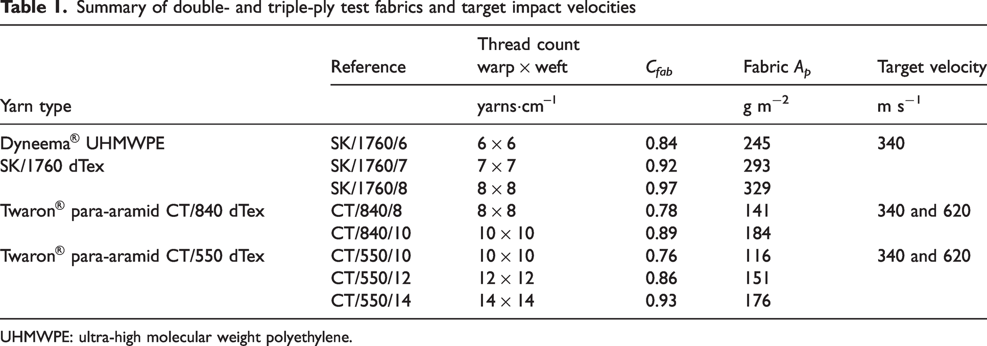
UHMWPE: ultra-high molecular weight polyethylene.
The cover factor (Cfab) for warp (
wp
) and weft (
wf
) yarns was calculated from the ratio between the physical yarn diameter 

Ballistic testing was conducted on a helium gas gun with a pressure of up to 300 bar. A schematic of the test set-up used can been seen in Figure 1. A stainless steel 0.7 g sphere projectile, equal to 5.56 mm caliber, was used in place of a 1.1 g chisel-nosed fragment simulating projectile (FSP). The lower mass of the sphere enabled greater differentiation between pre-impact and post-impact velocities. Unlike a FSP, the sphere projectile has a consistent strike face regardless of impact angle, thus allowing consistent and accurate comparisons between test fabrics. The projectile was fired from a 7.62 mm caliber, 1-in-12 twist rifled barrel using a bespoke nylon sabot used to help achieve the maximum velocity possible with a given firing system. Projectile impact was performed at 340 and 620 m·s−1, below and above the critical velocity of the single-ply fabrics. Three high-speed cameras (Photron FASTCAM SA5, 50 mm Nikon lens and Bowen’s flash lamp) were used, with one mounted vertically above the sample and two to the rear.
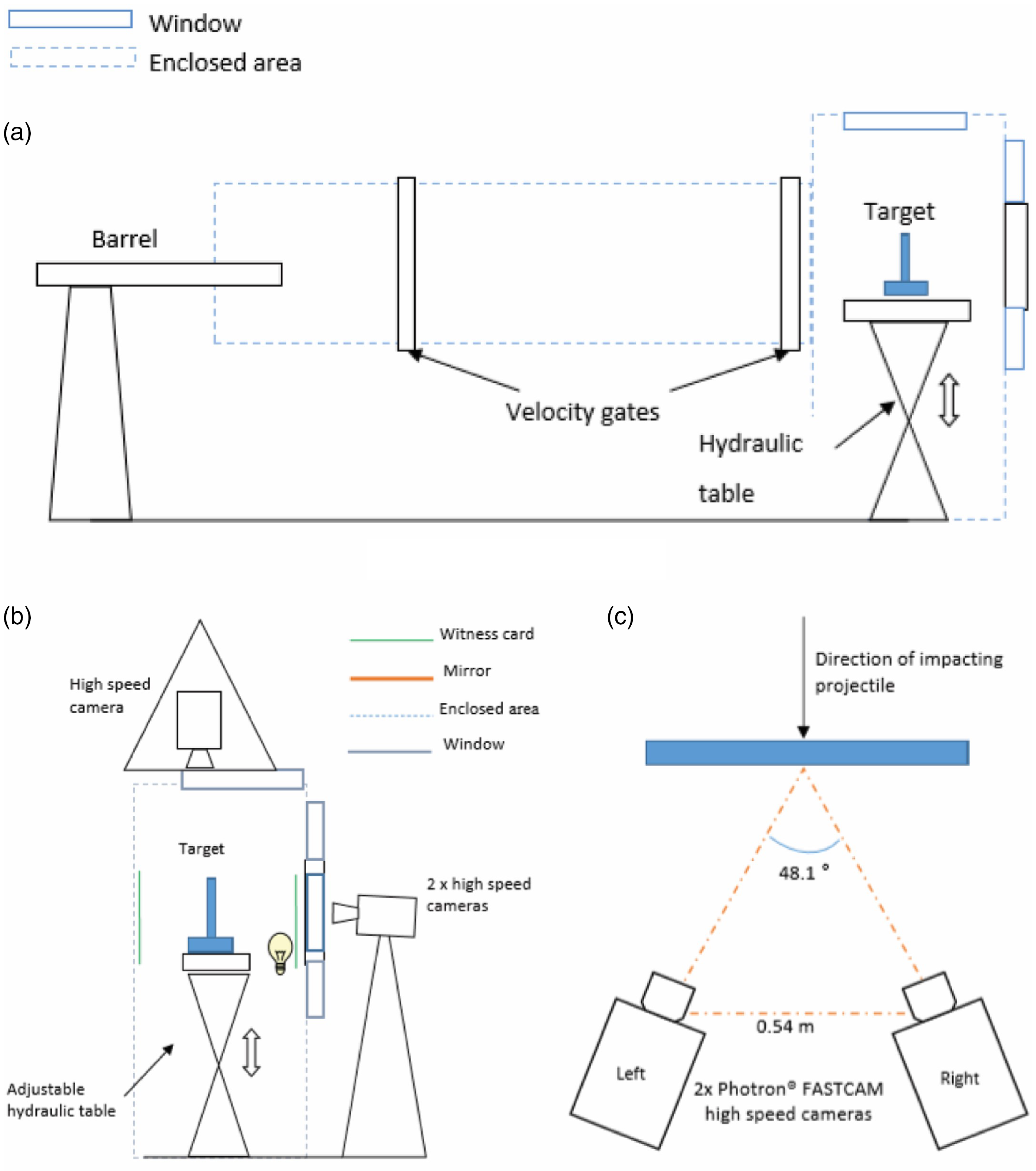
Schematic of the test set-up used for ballistic testing of fabrics for energy absorption and transverse and strain wave propagation.
The first ballistic test was performed to measure the energy absorbed by the target from an impacting projectile. Double- and triple-ply combinations of fabrics were tested in both low- and high-velocity regimes. Test fabrics were cut to 150 mm × 150 mm then mounted and clamped in a bespoke aluminum frame. The frame was designed to clamp the four corners, leaving the edges free. Energy absorbed by the fabric was calculated using Equation (3), where m is the projectile mass and Vi and Vr are the impact and residual velocities, respectively. The projectile remains intact and non-deformed during impact, so it can be assumed that there is no mass lost and all energy lost is transferred or absorbed by the target. SEA was determined by utilizing the mass per unit area (Ap) of each fabric:

Additional ballistic testing was performed to capture the in-plane and out-of-plane response of the target fabrics, utilizing the additional two cameras to the rear of the target. Digital image correlation (DIC) was used to analyze the relative velocities of the transverse waves induced by the impact. Target fabrics were cut to 300 mm × 300 mm, larger than those for energy absorption testing, to enable the transverse wave to travel further. Fabrics were stenciled with a unique speckle pattern using a foam roller and Marsh stencil ink. Fabrics were then clamped on all four edges causing the strike area to be reduced to 250 mm × 250 mm.
Results and discussion
Failure mode of multi-ply systems
Examination of the High Speed Video (HSV) revealed that the failure modes for all double- and triple- ply systems, under both velocity regimes, showed similar characteristics to that of the single-ply fabrics previously tested. 24 Figure 2 shows the behavior of the CT/840/10 triple-ply system, which was typical of all fabric types. In the low-velocity regime, there is yarn pulling and transverse wave propagation, while in the high-velocity regime, the yarns are fractured.
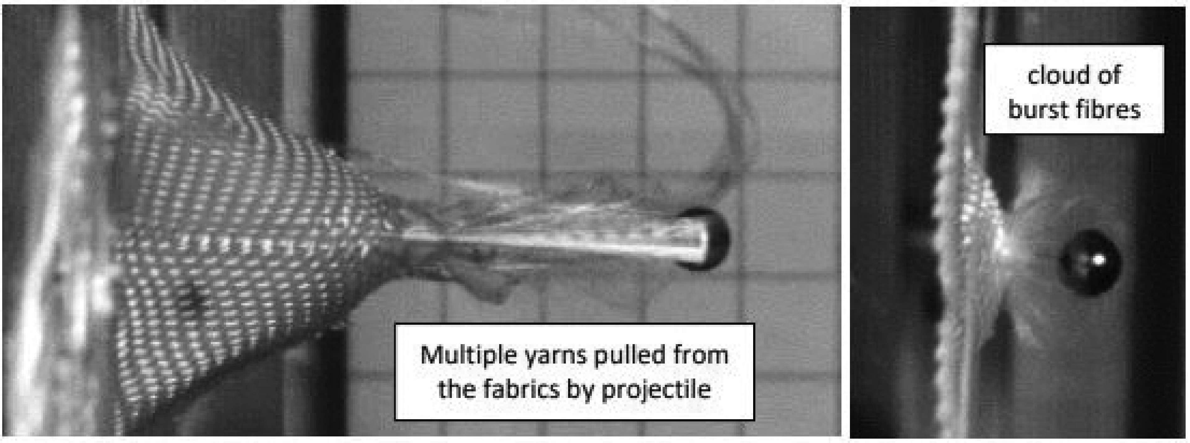
Impact of the triple-ply CT/840/10 system: (a) at 340 m·s−1 and (b) 620 m·s−1.
Homogenous multi-ply systems
The energy absorption of multi-ply targets were found using the residual velocity technique. Double- and triple-ply targets of each of the para-aramid fabrics were impacted at 340 m·s–1 ± 10 m·s–1 and 620 m·s–1 ± 10 m·s–1 to evaluate their response under both high- and low-velocity regimes. Limited testing was conducted on the double- and triple-ply UHMWPE SK/1760/XX specimens; the fabrics having shown inconsistency as single plies compared to the para-aramid fabrics and, therefore, less conclusive results. The SK/1760/XX fabrics were tested under the low-velocity regime only, evaluating their transverse wave propagation providing a baseline performance to compare to the hybrid systems.
Energy absorption: homogeneous systems
Figure 3 shows the relative SEA of single-, double-, and triple-ply targets in the low-velocity regime. CT/840/10, CT/550/12 and CT/550/14 fabrics show an increase in SEA with increasing ply count. However, the two fabrics with lower Cfab (CT/840/8 and CT/550/10) had lower SEA for two-ply targets compared to the single ply target, while there was an increase in SEA going from two plies to three plies. The difference in SEA between single- and double-ply systems was not found to be statistically significant for any of the para-aramid fabrics. However, the SEA of the triple-ply systems was significantly higher than the SEA of the single and double plies of the CT/840/10, CT/550/12, and CT/550/10 fabrics (Tukey honestly significant difference (HSD) q = 3.8, α = 0.05). The remaining two fabrics (CT/550/14 and CT/840/8) showed no significant relationship between the SEA and ply count. This was expected for CT/840/8, which was the only fabric that did not show a maximum SEA with the addition of a third layer. The lack of statistical significance with the CT/550/14 fabrics is attributed to the higher variance in measured SEA of the double- and triple-ply targets.
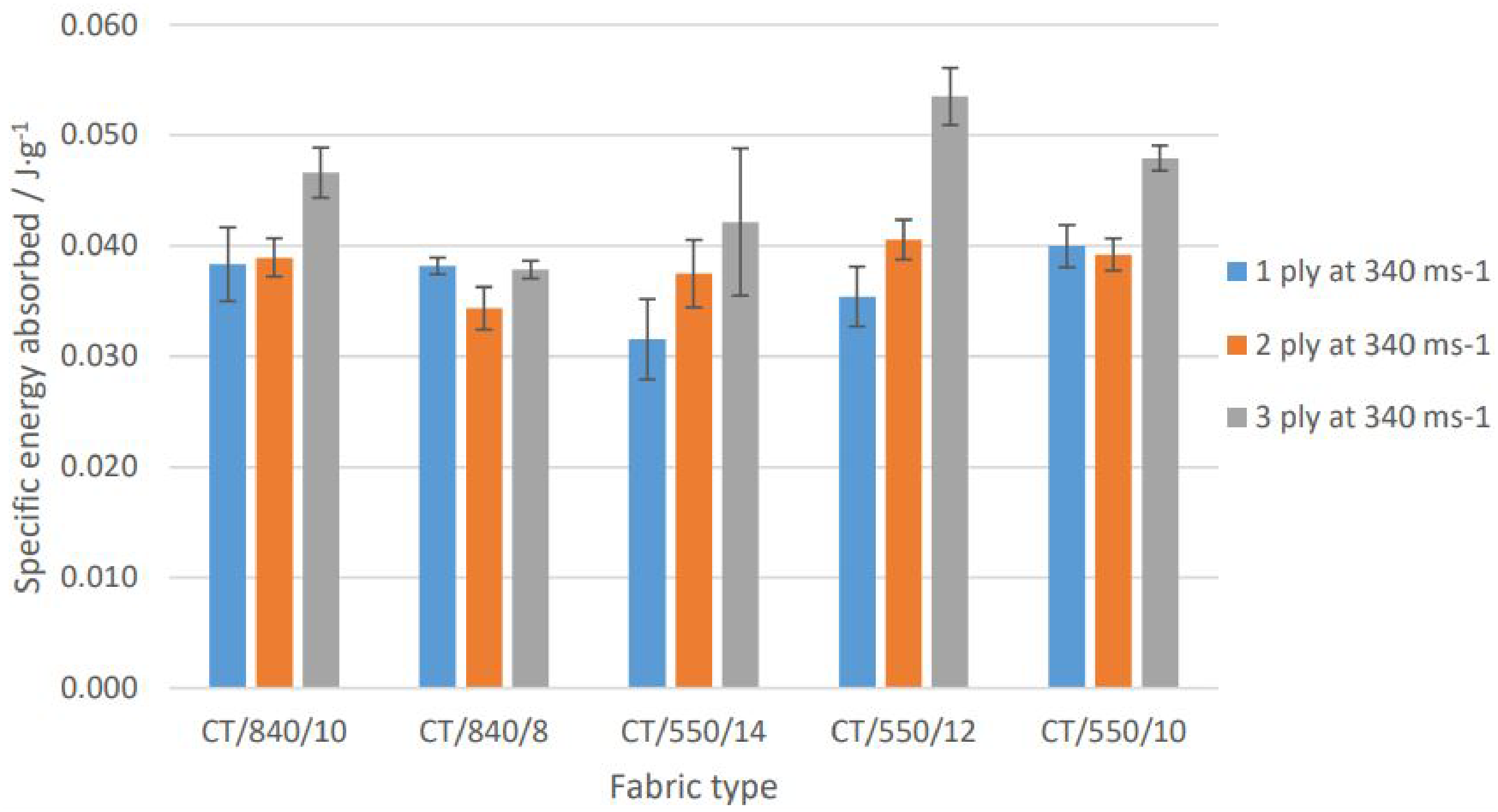
Specific energy absorbed of multiple-ply para-aramid fabrics impacted at 340 m·s−1. One-, two-, and three-ply systems. Error bars depict standard errors.
It is also noted that the relative ranking of the individual fabrics varied with additional ply counts. For both para-aramid fabric sets, the lower Cfab fabrics, CT/840/8 and CT/550/10, were surpassed by fabrics of a higher Cfab within the set CT/840/10 and CT/550/12.
Figure 4 shows the SEA data for multi-ply systems of the SK/1760/XX UHMWPE fabrics in the low-velocity regime. All the fabrics showed an increase in energy absorbed with the addition of a second ply, followed by a reduction in SEA with the addition of a third. Statistical analysis highlighted no significant differences with any of the UHMWPE fabrics with increasing ply count (analysis of variance (ANOVA) Fcrit = 3.89, P < 0.05). This is attributed to the relatively large variance within the data sets combined with the overall lower SEA values, compared to the para-aramid fabrics. The average energy absorbed for the UHMWPE fabric systems (0.02 j·g−1) was half the mean value of the para-aramids.
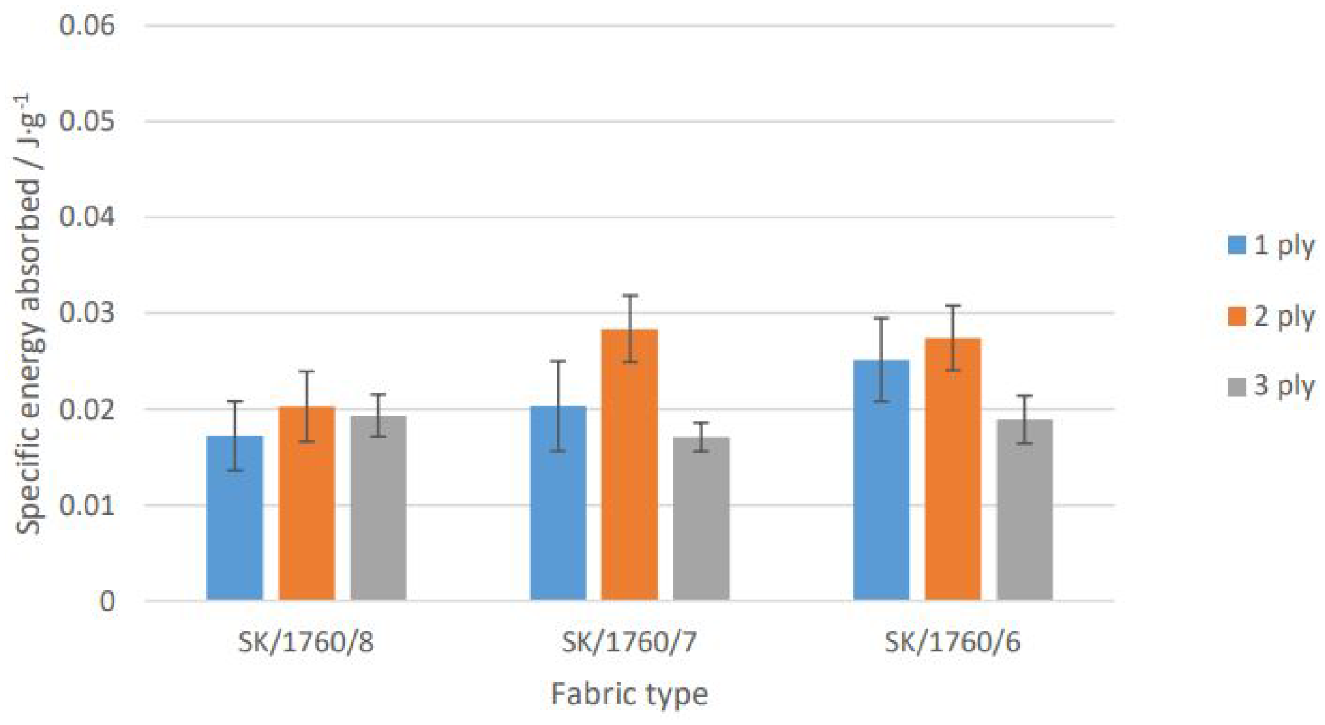
Specific energy absorbed of multiple-ply ultra-high molecular weight polyethylene fabrics impacted at 340 m·s−1. One-, two-, and three-ply systems. Error bars depict standard errors.
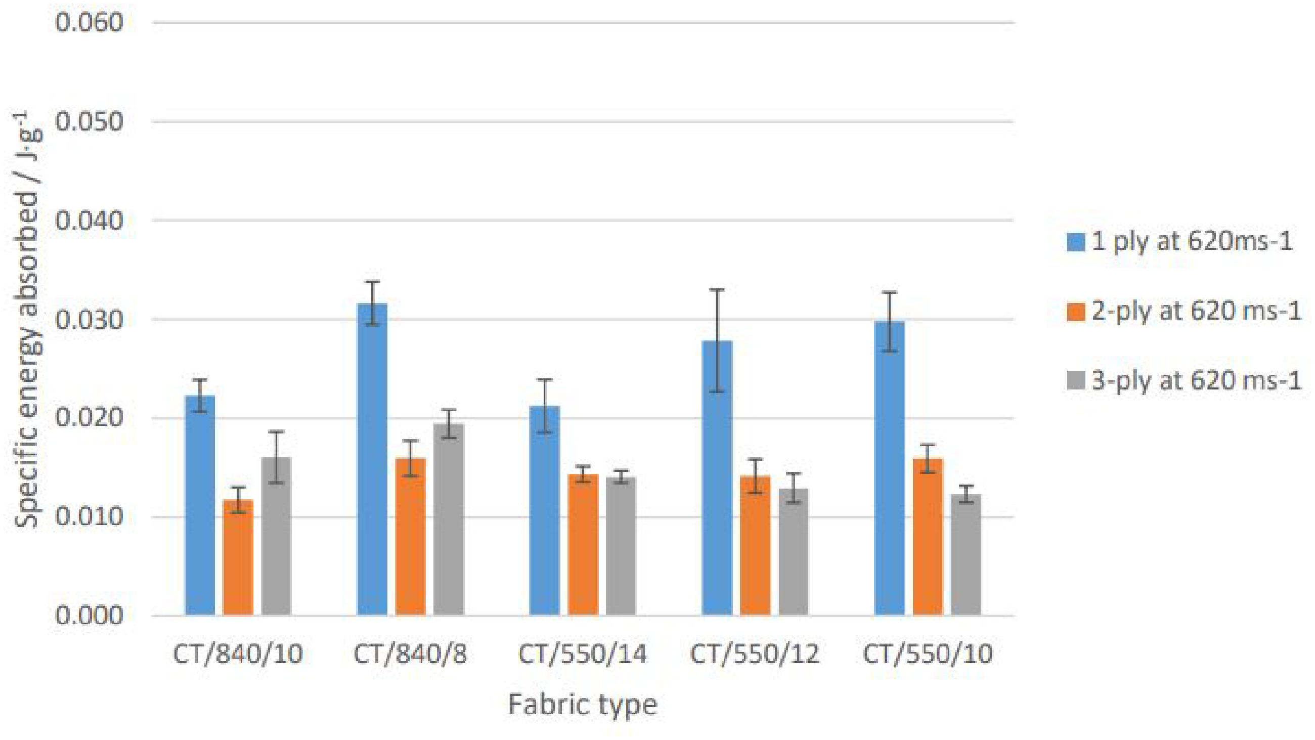
Figure 5 shows the SEA of para-aramid fabrics in the high-velocity regime, where they all showed a significant reduction in SEA as multi-ply systems compared to a single-ply fabric (ANOVA Fcrit = 3.89, P < 0.05). This reduction was statistically significant between the single-ply systems and the multiple-ply systems (Tukey HSD, α < 0.05) but not between the double- and triple-ply systems for any fabric. This might be expected, given the smaller percentage difference in SEA between double- and triple-ply systems (2–26%) compared to that of single- and double-ply (39–65%).
Specific energy absorbed of multiple-ply para-aramid targets impacted at 620 m·s−1. One-, two-, and three-ply systems shown. Error bars depict standard errors.
An empirical study by Cunniff 9 highlighted a reduction in the SEA with increasing ply count. A theoretical spaced system was used to show that the same fabrics acting independently were more mass efficient than a stacked woven fabric system. This phenomenon was common, to a greater or lesser extent, to all fabrics tested, including examples of plain-woven para-aramid and UHMWPE. The disparity in the performance between spaced and stacked systems led Cunniff to conclude that layer-to-layer interactions were responsible for these detrimental effects, which might reduce with less interference.
In addition, Duan et al. 25 conducted a finite element (FE) analysis of the influence of friction on energy absorption, which included evaluation of both projectile–yarn friction and inter-yarn friction. The energy absorption increased with the application of a fixed coefficient of friction (0.5) at crossovers and between the projectile and yarns, but the increases in energy absorption were not cumulative. The inter-yarn friction restricted the lateral movement of the yarn at the point of impact, ensuring that a greater number of yarns were broken, while it also hindered the decrimping process, causing the yarns to fail earlier. The projectile–yarn friction acted to dissipate the strain loading to the periphery of the projectile. This had the effect of delaying the fracture of the impacted yarns. The higher friction of para-aramid compared to UHMWPE and the additional friction generated from higher Cfab fabrics helps explain the observations in this study and support the conclusion of Duan et al.
Transverse wave propagation: homogeneous systems
All multiple-ply systems were impacted at 340 m·s–1 to evaluate the resulting transverse wave velocity. Figure 6 shows the transverse wave velocity and the Cfab for double- and triple-ply systems, which followed a similar pattern to that observed in the single-ply study, 24 the velocity reducing with an increase in Cfab for each fabric set. Statistical analysis identified significant differences in the transverse wave velocity with Cfab (F), specifically between fabrics having the highest and lowest Cfab within each fabric set (Tukey HSD, α < 0.05). Comparison between each fabric set shows that the CT/840/XX fabric set and the CT/550/XX set had reversed ranks compared to the single-ply fabrics, with the CT/550/XX fabrics having the highest transverse wave velocities at any given Cfab. In general, the transverse wave velocity showed no statistically significant variation with increasing ply count, except for the CT/550/10 fabric, where a significant difference between the single-ply system and both the multi-ply systems was highlighted (one-factor ANOVA Fcrit = 4.25, P < 0.05).
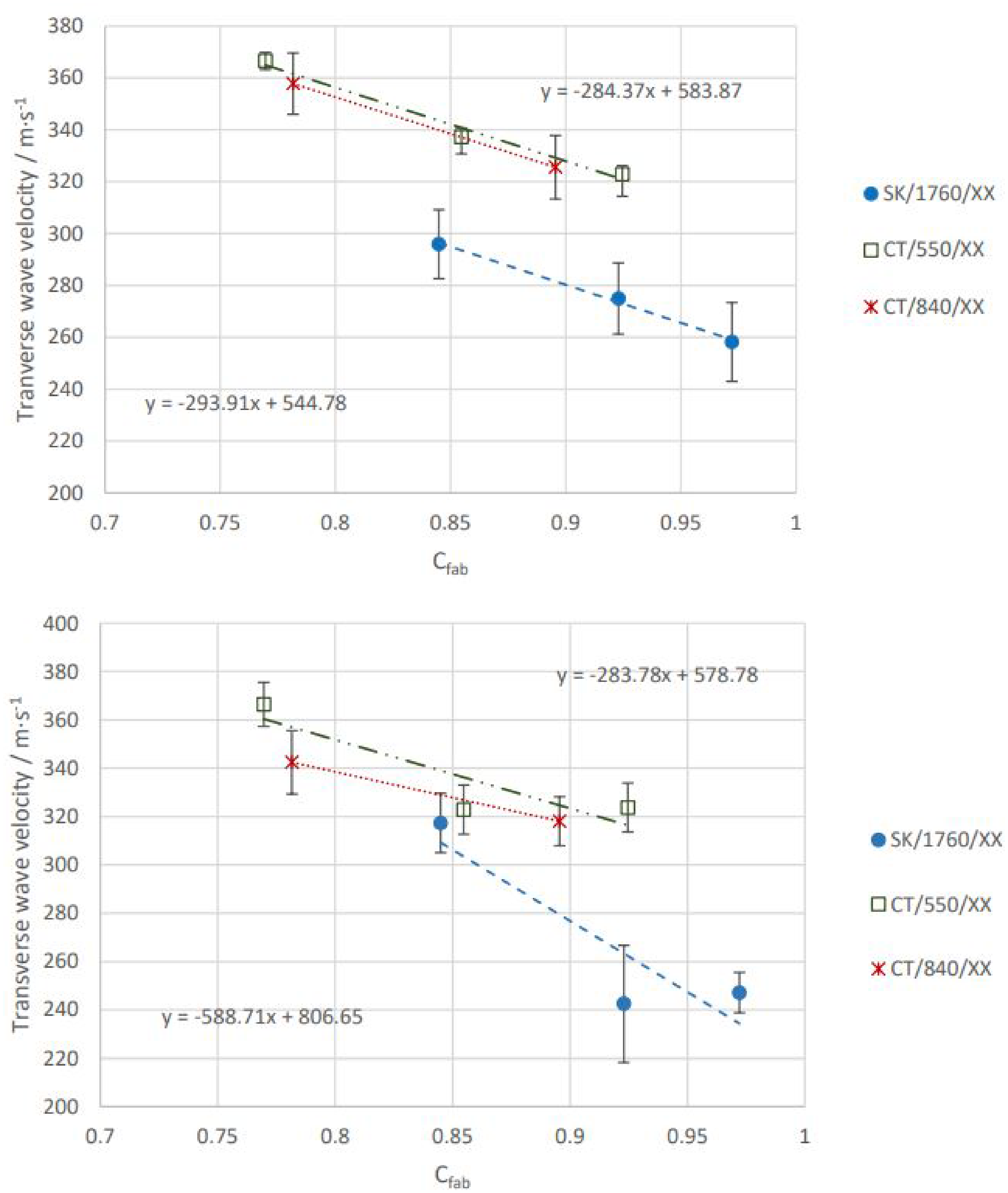
Mean transverse wave velocity of (a) two-ply systems and fabric Cfab and (b) three-ply systems and fabric Cfab. Error bars depict standard errors.
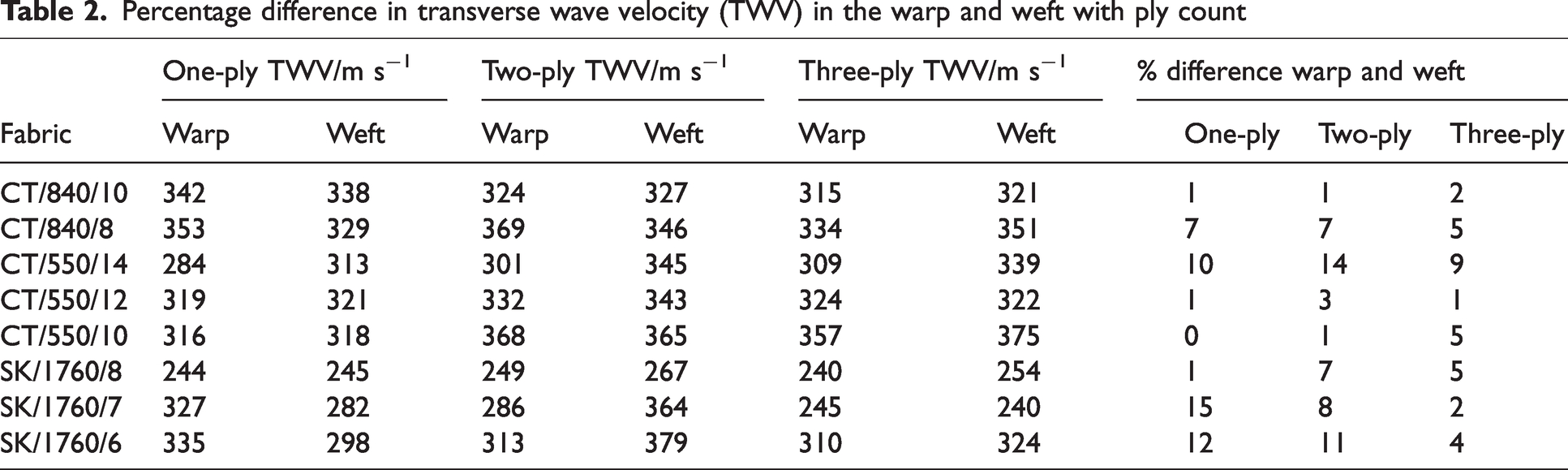
While no statistical significance was found between warp and weft wave velocities, the data shows that the percentage difference, calculated by the absolute difference between values divided by the mean of values, between the warp and weft (Table 2) mirrored the results of the single-ply testing in the double-ply systems. The greatest percentage differences occurred in the less balanced fabrics, CT/550/14, SK/1760/7, and SK/1760. However, the difference was less apparent in the three-ply systems where only the CT/550/14 fabric had a pronounced difference.
Percentage difference in transverse wave velocity (TWV) in the warp and weft with ply count
The transverse wave propagation in a fabric is fed by the strained yarns as the longitudinal strain wave propagates. The wrapping effect reduces the peak strain in successive layers of a multiple-ply system and, correspondingly, the transverse wave velocity should also decrease in each layer. The slower transverse waves in the rearward layers of the system will then confine the preceding layers and would be marked by a net velocity reduction at the rear of the system. It has been theorized that this disparity in wave velocity creates increased compressive stress owing to the confinement of the forward layers, which would lead to a more rapid accumulation of strain and premature failure of the principal yarns.9,14 However, there was no clear reduction in the transverse wave velocities of the individual multiple-ply systems, and the expected system effects had the rearward layers restricting the transverse wave propagation of the forward layers. This may be because the velocity range was too small given the standard deviation of the data. However, comparisons between fabric sets revealed that, for any given Cfab, the CT/550/XX fabric set had a higher transverse wave velocity than the CT/840/XX fabric set, while the reverse was true for the single-ply studies. 24
The higher linear density CT/840 yarn means that the fabrics are thicker than the CT/550/XX fabrics of the same Cfab and, based on the yarn wrapping theory, will have a lower peak strain in the rearward layers. As the transverse wave is dependent on the strain in the yarn, 26 the disparity in the transverse wave velocity should be greater from the strike face to the rear in the CT/840/XX systems compared to the CT/550/XX systems. This effect cannot be confirmed directly from the SEA data. However, this effect may have driven the multi-ply system rankings, which were dominated by the CT/550/XX fabrics and where the CT/840/XX fabrics fell in rank. Although this is not robust evidence, it suggests that fabrics constructed from the lower linear density CT/550 yarn would be better placed at the rear of multi-ply systems, as they are less likely to impede the transverse wave velocity in the forward layers.
System effects of homogeneous multi-ply systems
For homogeneous systems, the effects of layering on the efficiency of the system are considered in the low- and high-velocity regimes and associated with the loss of efficiency previously noticed in soft armor systems as their mass increases. 9 These ‘system effects’ are discussed in relation to the SEA and transverse wave propagation, determining how the balance of the strain (Eε) and frictional (Ef) energy absorption components of each layer vary through the thickness of the system. This is illustrated in Figure 7 and later pictured for two of the test fabrics (CT/840/8 and CT/550/14) in Figure 8.
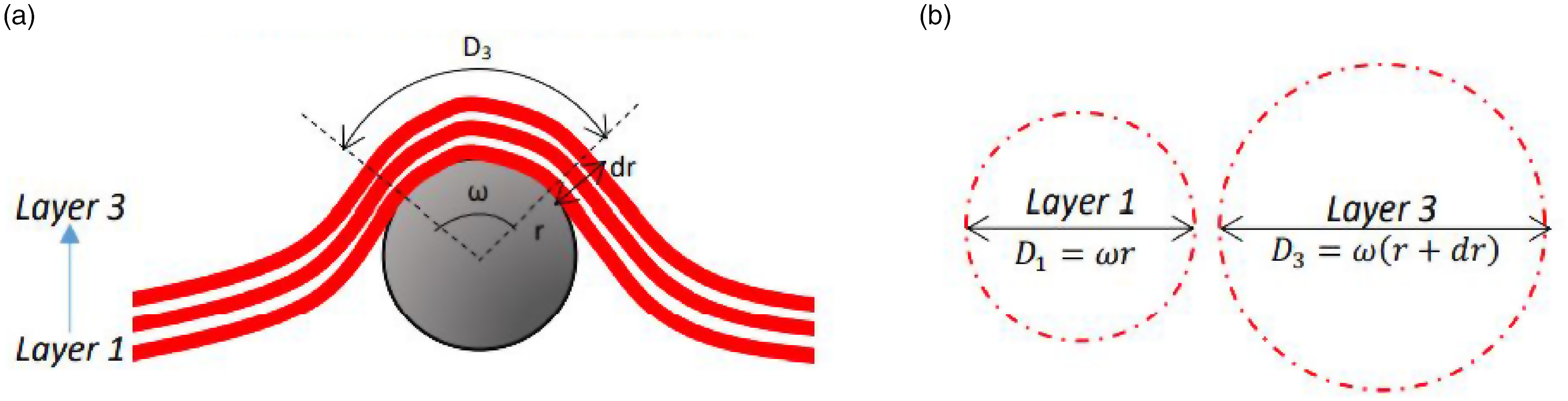
(a) Fabric wrapping around a projectile in the low-velocity regime and (b) The relative area engaged directly by the projectile. Here, r is the projectile radius, ω is the contact angle of fabric with the projectile, a1 is the diameter of the first layer, and ai is the diameter of the fabric area engaged.
Impact of CT/840/8 and CT/550/14 para-aramid fabrics in the low-velocity regime: (a) as the projectile begins to deflect the fabric and (b) as the projectile begins to pull yarns from each weave (color online only).
The yarn wrapping increased the contact angle (ω) between the projectile and fabric, allowing strain to accumulate over a greater fabric area. In the rearward layers of the systems, the wrapping effect has been shown to be compounded owing to the thickness of the system (dr), and the net area of fabric directly engaged with the projectile increases with each successive layer (Figure 7). 27 For the systems tested, the yarn wrapping had two effects: (1) a greater number of yarns and yarn crossovers per layer through the thickness of the system were directly loaded by the projectile as it impacted; and (2) a strain gradient developed in the system decreased from the strike face to the rear owing to the strain being transferred to a greater area in each successive layer.14,27
The increase in SEA observed in the multiple-ply systems (Figure 3) can be attributed to these effects, when the energy absorbed (Eabs) of each layer is considered in terms of the contributing energy absorption components. Effect (1) increases the number of crossovers included in the impact event layer by layer which, in turn, increases Ef, in line with the published frictional models.28–30 In addition, effect (2) will reduce strain in the rear layers of the system, delaying the critical strain accumulation and, therefore, increasing the engagement time of the projectile with the system. Therefore, Ef will increase with ply count in the low-velocity regime, each successive layer contributing more than the preceding layer.
The results of this study provide evidence supporting the published theory, which suggests that Ef begins to dominate below the critical velocity and increases in dominance as the impact velocity/strain loading decrease. 31 The systems that showed the greatest increase in SEA with ply count were constructed from the para-aramid fabrics with high Cfab (0.84–0.92) and the lower linear density yarn (CT 550 dTex). For these fabrics, both the frictional forces between individual yarns and the thread counts are greater than in the other fabrics. The thread count is important, as friction has also been shown to increase with the number of yarns pulled32–35 and because the tighter weaves tend to limit yarn migration as the projectile begins to deflect the fabric. 29
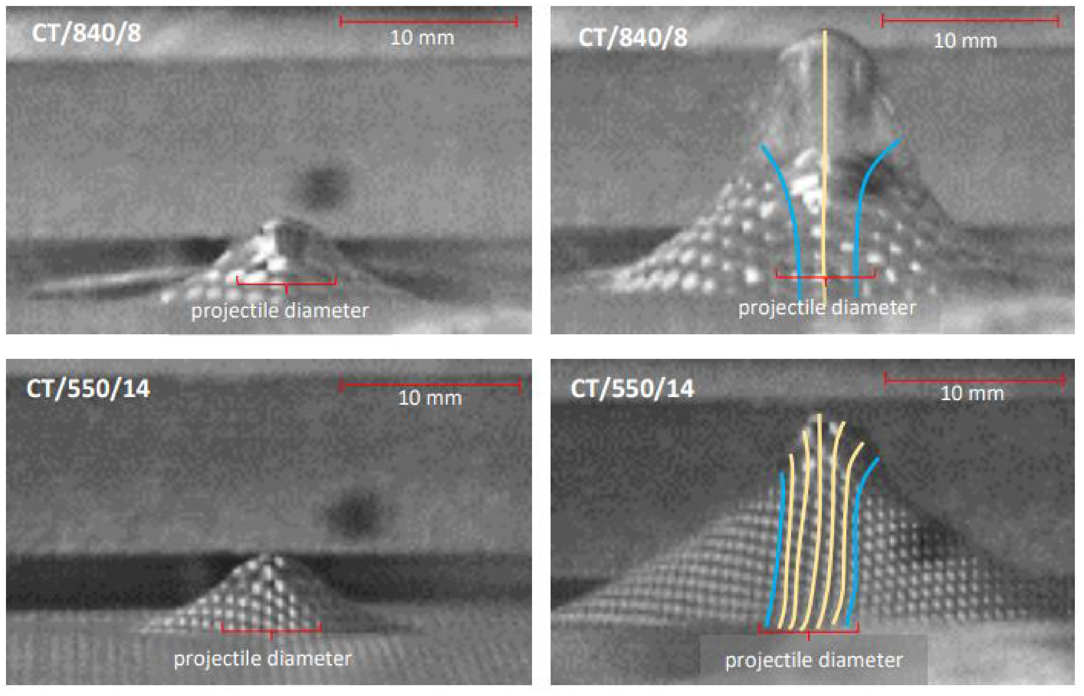
This is shown in Figure 8. Figure 8(a) shows the yarns engaged as the projectile begins to deflect the fabric and the fabrics can be seen to wrap around the projectile. The projectile’s diameter is highlighted to illustrate the variation in the number of yarns engaged for each fabric type – approximately three warp yarns for CT/840/8 and approximately seven warp yarns for CT/550/14. Figure 8(b) shows the yarns subsequently being pulled from the weaves – the yarns still engaged by the projectile are highlighted by orange lines and those that have slipped off the projectile, in blue.
The increasing dominance through the system of Ef in higher friction fabrics is reinforced by the results of lower friction, lower thread count UHMWPE SK/1760/XX fabrics. These showed a decrease in SEA as a triple-ply system suggesting that, as friction has an additive effect, Eε must have decreased with ply count and that, because the fabrics had lower inter-yarn friction, the increase in Ef was insufficient to compensate for the loss. These observations suggested that, for multi-ply systems in the low-velocity regime, there was a benefit to both (A) a high fabric Cfab, and (B) fabrics constructed of low linear density yarn; therefore, these fabrics would be optimally placed at the rear of a soft armor system.
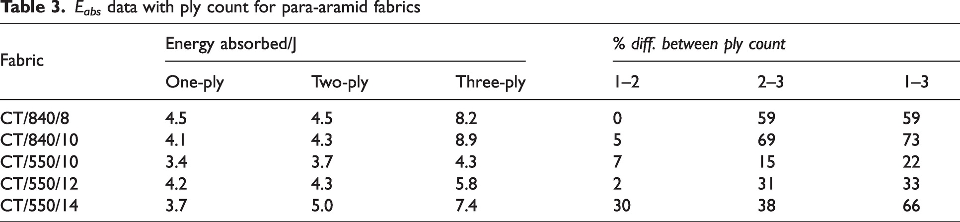
In the high-velocity regime, the frictional component of Eabs is lower, with less fabric involved in the impact event owing to reduced yarn wrapping and the absence of transverse waves. Therefore, the principal energy absorption mechanism is strain loading and the work of fracture of the principal yarns. 31 For the systems tested, the sharp drop in SEA noted when moving from single- to double-ply impacts was greater than expected considering published data on system effects, which shows discrepancies between spaced and stacked systems of up to 30%. 9 This was also reflected in the Eabs data, summarized in Table 3, which showed that the percentage difference increase in Eabs was between 0% and 7% for the majority of the double-ply systems compared to their equivalent single-ply systems and much greater (15–69%) with the addition of the third ply. This suggests that the second fabric ply added very little additional value to Eabs, with the exception being the highest Cfab fabric, CT/550/14 (Cfab = 0.92), which showed a 30% difference.
Eabs data with ply count for para-aramid fabrics
This was attributed to the alignment of the individual layers within the double-ply system. If the yarns in each weave nestled such that the yarns of the rear ply were misaligned with the front (Figure 9), then the projectile may have engaged directly with yarns of only one layer, with the yarns in the second layer migrating away from the point of impact slipping off the projectile. This would lead to a reduction in yarns fractured for the systems and a reduced Eabs.
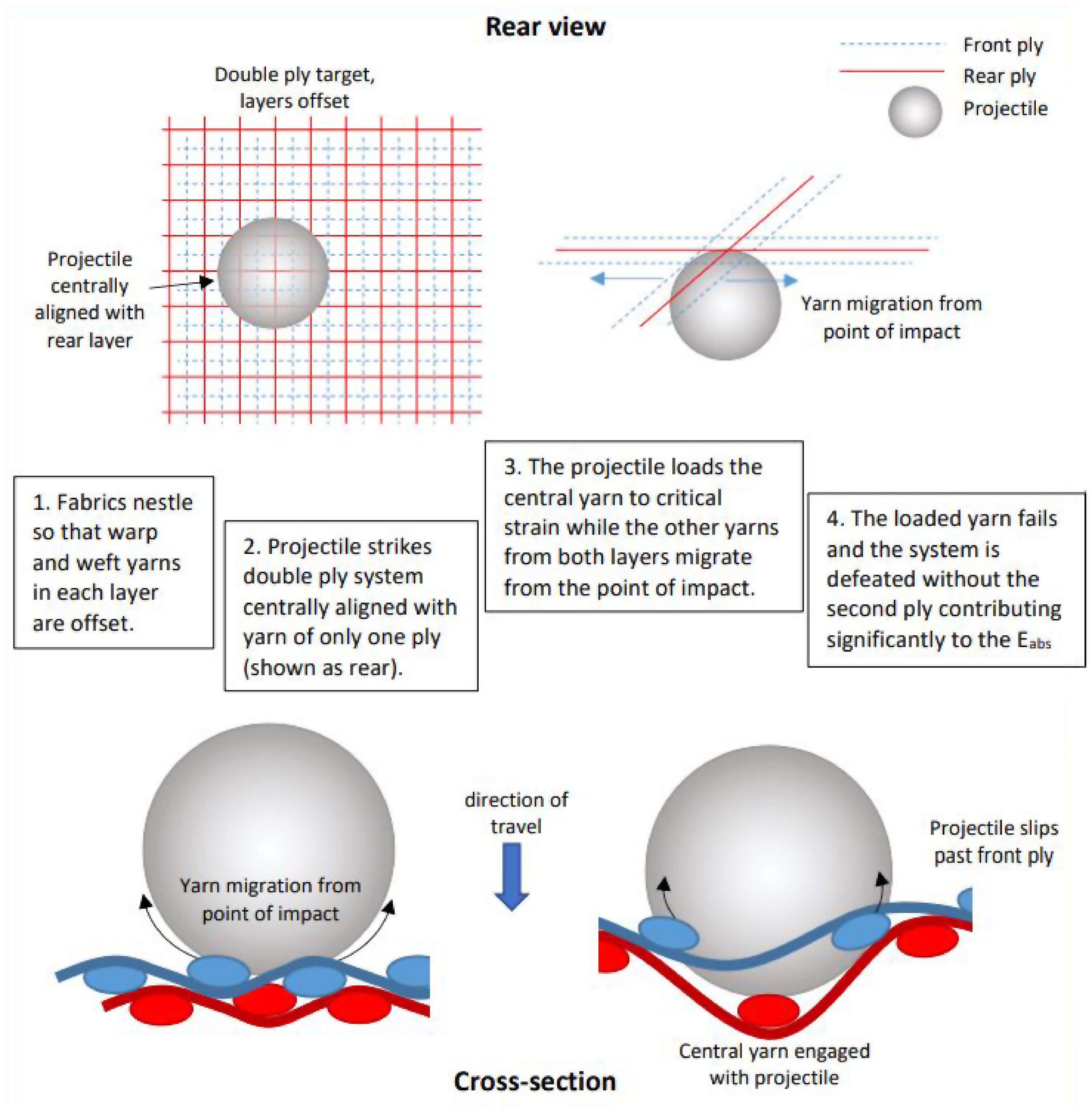
Double-ply fabric alignment showing the projectile in direct contact with only one of two layers.
This also explains the higher Eabs in the CT/550/14 double-ply system, which has the highest Cfab combined with the lowest yarn linear density and places more yarns in the path of the projectile. The high Cfab also limits the yarn movement away from the point of impact, 29 enforcing the engagement and fracture of yarns from both layers. The general increase in Eabs with the addition of the third layer suggests that it improved the engagement of the projectile with the systems, yet not sufficiently to restore the mass efficiency; the SEA was still lower than for the single-ply systems.
For the triple-ply systems, the greatest percentage difference in Eabs was seen in both the CT/840/XX fabrics and the CT/550/14 fabric. The CT/840 yarns have a higher ultimate breaking strength than the CT/550 yarns 24 and will have a higher work of fracture, absorbing more energy per yarn broken. The CT/550/14 fabric has more yarns in its path and, as shown in the single-ply study, 24 will have a higher number of yarns fractured so that the combined work to fracture for these yarns will again be greater for this system.
Several methods have been investigated to limit or remove yarn slippage in the front plies of the strike face to maximize the absorption capability of the fabric. It is known that increasing the friction between the crossover yarns can increase the fabric properties 36 ; therefore, efforts have focused on this. Surface treatment has generated significant attention through the application of shear thickening fluid 37 or surface treatments such as plasma. 38 Despite the improvement in properties, these approaches increase the stiffness and weight of the fabric, which goes against soft armor principles. Recent approaches have investigated altering the fabric structure to maintain fabric stability through stitching to reduce slippage and increase friction. 39 Within weaving itself, the approach of three-dimensional (3D) weaving, where a through-thickness binder yarn is incorporated into a multilayer fabric during the weaving process, could prove an attractive solution, having already shown significant improvement in delamination resistance and fabric stability within composite materials.40–42
Hybrid multi-ply systems
Further residual velocity ballistics tests were conducted on double- and triple-ply hybrid systems where dissimilar fabrics were selected and stacked together. To compare the directionality of the systems, each combination of fabrics was tested with both faces independently used as the target’s strike face. Introducing dissimilar layers to a system increases the complexity of the impact response. To minimize the additional complexity, each hybrid system was constructed with fabrics of a single yarn type with successive layers varying by Cfab. The only exception to this was double-ply para-aramid/UHMWPE System 3, which was included for comparison with Cunniff’s study. 9
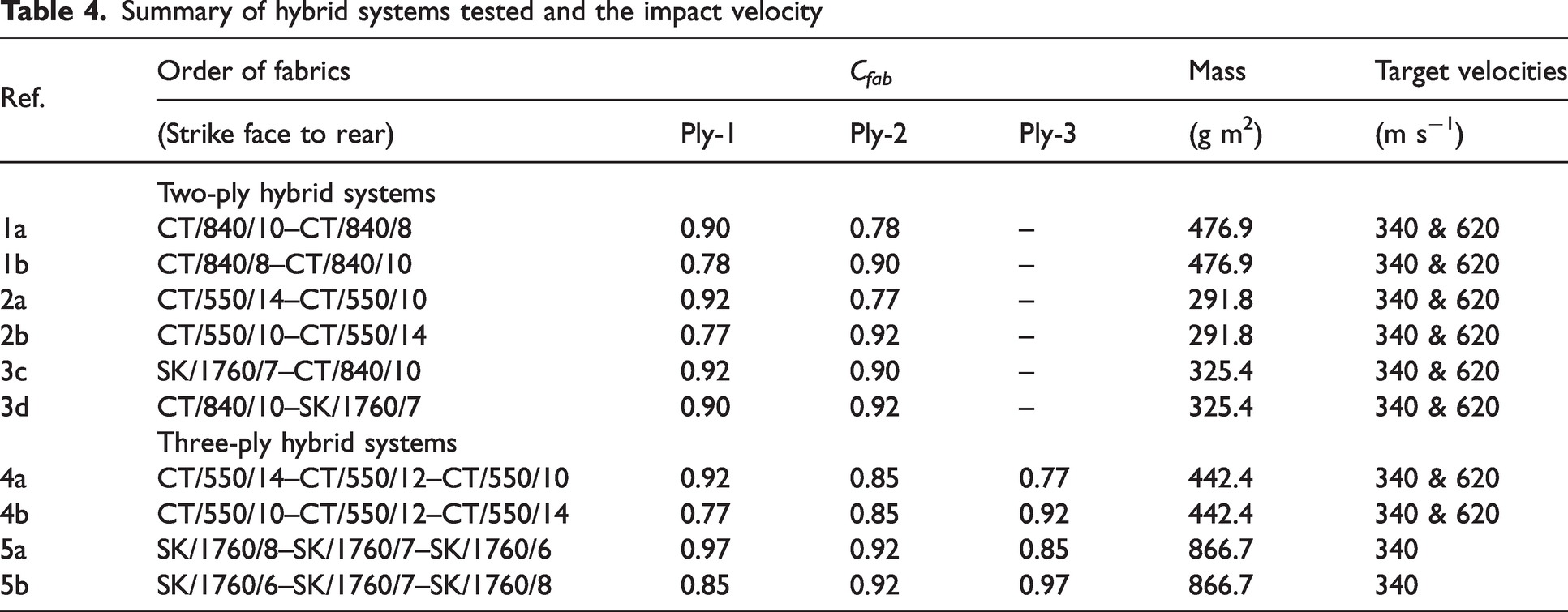
Table 4 outlines the fabric combinations for both two- and three-ply hybrid systems, including the order in which the fabrics were placed within the system. Systems denoted ‘orientation a’ are ordered with fabrics decreasing in Cfab and systems denoted ‘orientation b’ are the reverse with fabrics increasing in Cfab with respect to the strike face. The Cfab of the fabrics of Systems 3c and 3d were selected to be as close as possible (0.90 and 0.92). For these systems, ‘c’ denotes that the UHMWPE is on the strike face and ‘d’ that the para-aramid is on the strike face.
Summary of hybrid systems tested and the impact velocity
Energy absorption: hybrid systems
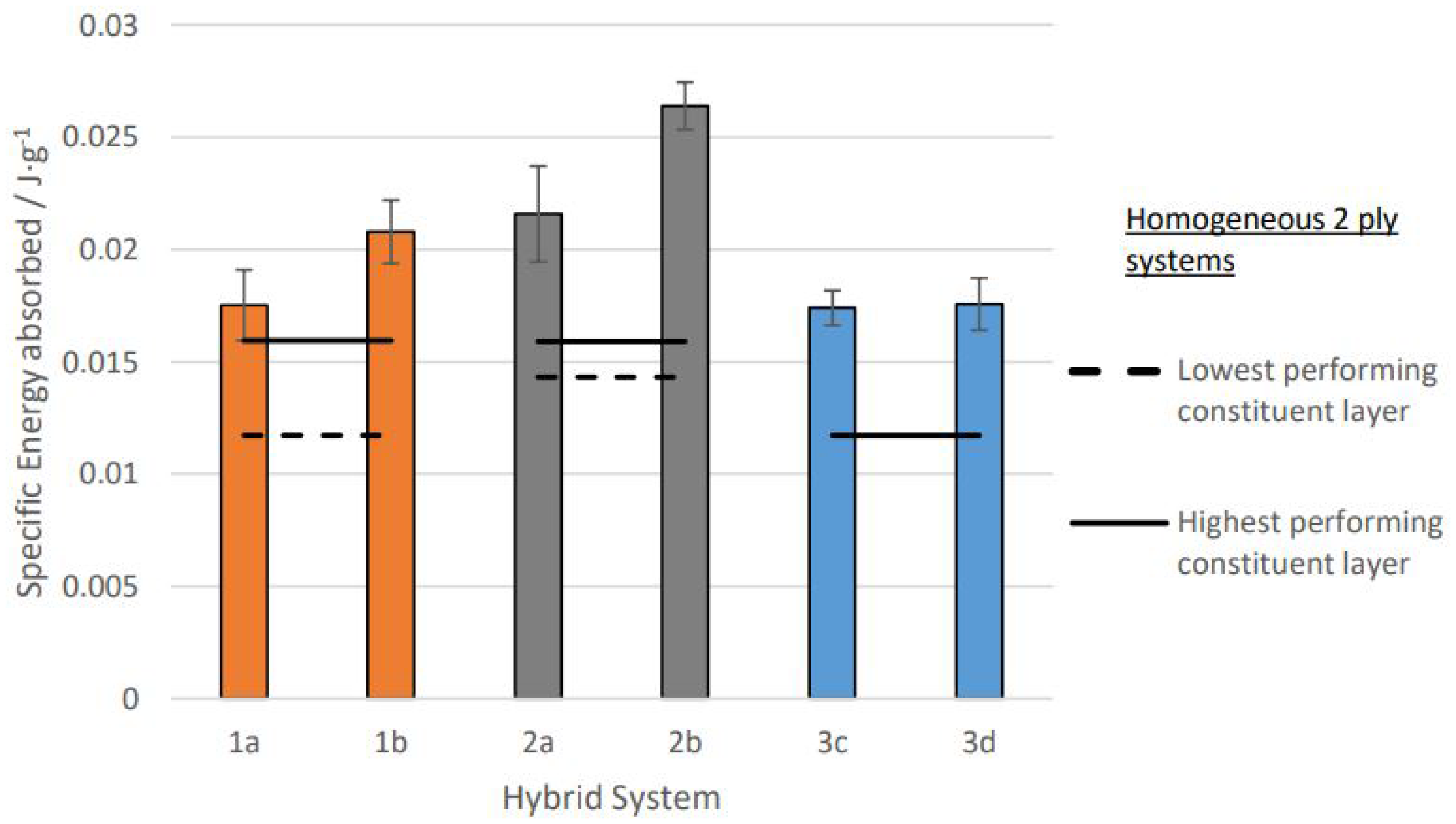
Figure 10 presents the SEA for each of the double-ply hybrid systems (Systems 1a–3d) in the low-velocity regime. The highest and lowest SEA for double-ply homogeneous systems made from the constituent fabrics are referenced by the solid and perforated lines, respectively, to aid comparison.
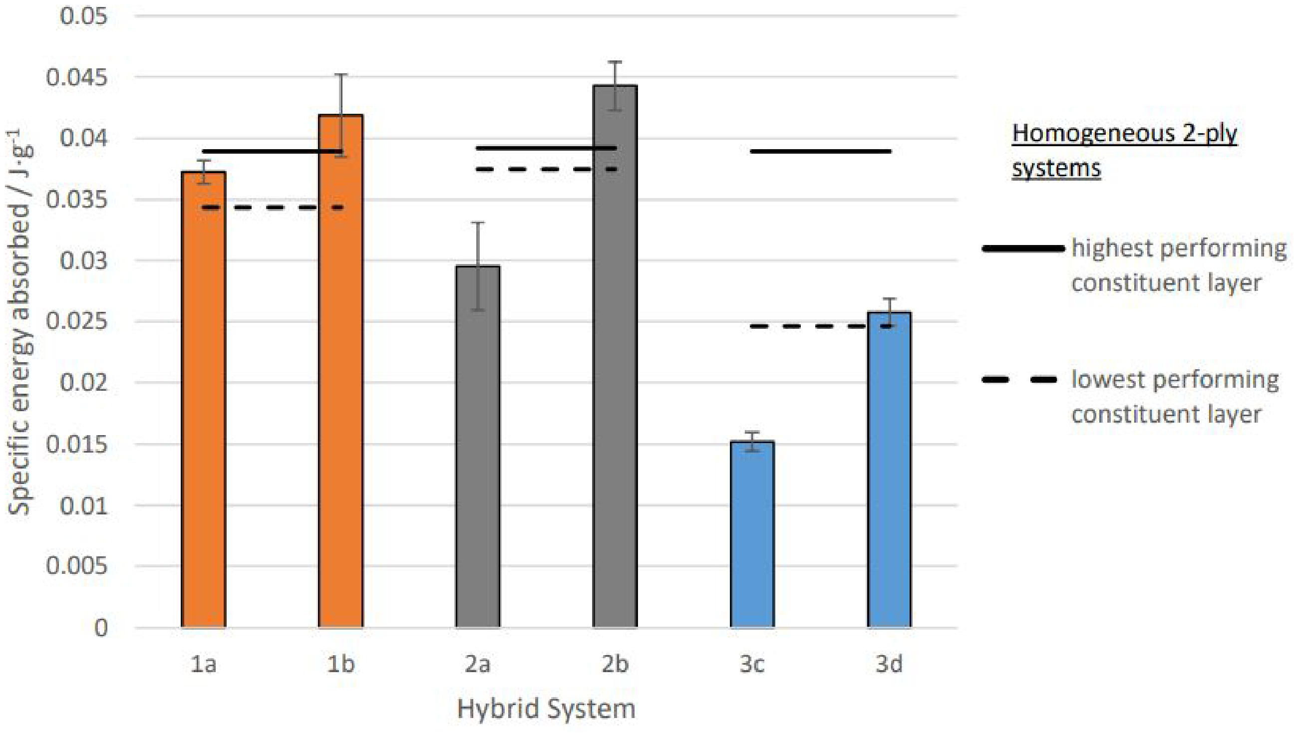
Specific energy absorbed (SEA) of two-ply hybrid systems in the low-velocity regime. Solid and perforated lines indicate SEA of two-ply homogeneous systems of the constituent fabrics for comparison. Error bars depict standard errors.
All three hybrid systems show a variation in the SEA dependent on the order of layers within the system. The SEA was greater for the ‘b’ orientation where the higher Cfab fabrics were placed at the rear of the system and the ‘d’ orientation, which had the UHMWPE to the rear of the para-aramid. Statistical analysis showed that this difference had a significant effect for Systems 2a/2b and 3c/3d but not for Systems 1a/1b, which had a smaller measured difference (ANOVA Fcrit = 3.24, P < 0.05). The SEAs of Systems 1b and 2b were both greater than the highest performing double-ply homogenous systems of their constituent fabrics in the low-velocity regime, but this difference was not statistically significant. The SEA of Systems 3c and 3d showed no improvement over the double-ply homogenous system and, in the case of System 3c, where the SK/1760/7 UHMWPE fabric was on the strike face and the CT/840/10 the rear, the system performed worse, with a SEA significantly below the equivalent double-ply SK/1760/7 system. Within System 3, which combines para-aramid and UHMWPE, it is observed that the system performance is higher when UHMWPE is placed at the rear of the system. This supports the work of Chen et al., 43 who performed numerical and empirical investigation of the ballistic performance of various para-aramid and UHMPWE configurations, highlighting the higher performance when para-aramid is the strike face and UHMWPE as the rear layer. Similar behavior was observed for carbon/UHMWPE hybrid fabrics by Larsson and Svensson, 44 where again UHMWPE performed best at the rear of the system, which is related to the variation in velocity of the transverse cone forming within each fabric.
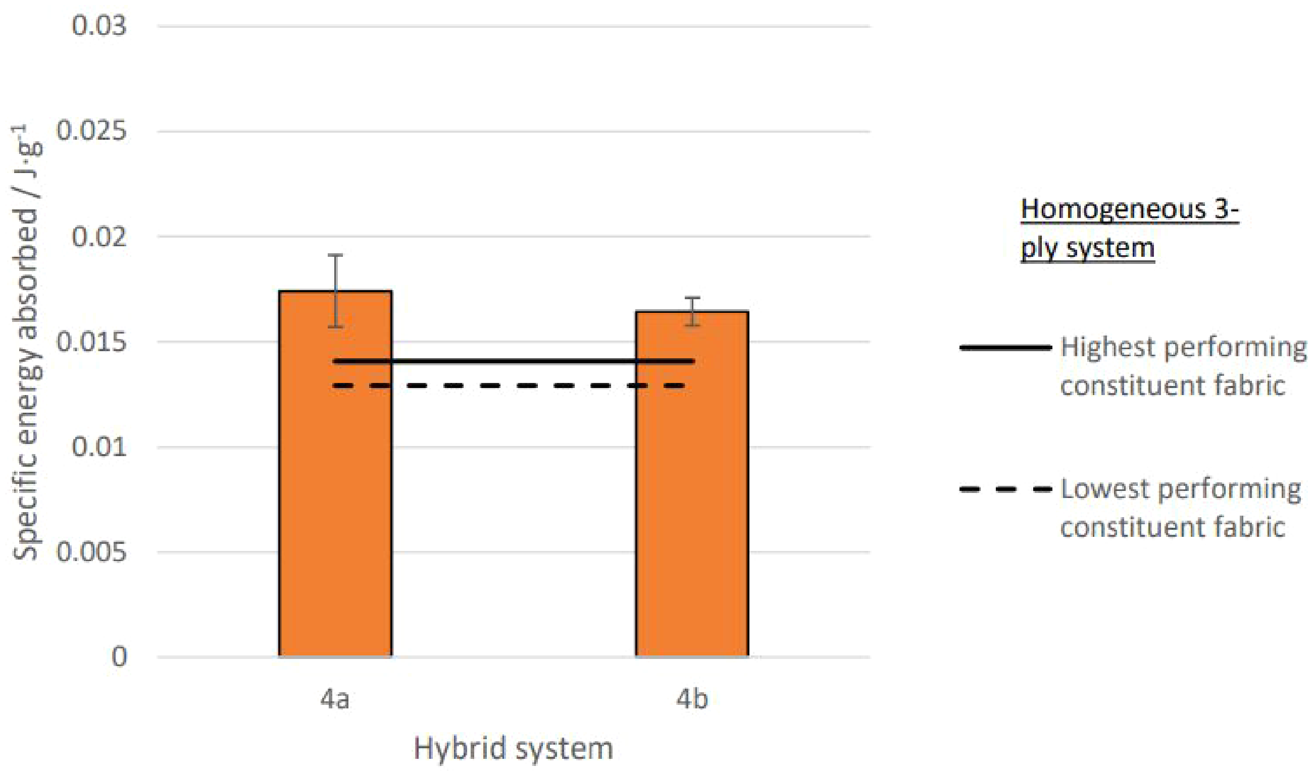
Figure 11 shows the relative SEA dependent on the layer order for the triple-ply hybrid systems under the low-velocity regime. Systems 4a/4b showed a dissimilarity in SEA consistent with the double-ply systems, where the ‘b’ systems, which had fabrics with increasing Cfab from the strike face to the rear, had greater SEA compared with the alternate arrangement. The difference in SEA with orientation was shown to be statistically significant for Systems 4a/4b (ANOVA Tukey HSD, P < 0.05).
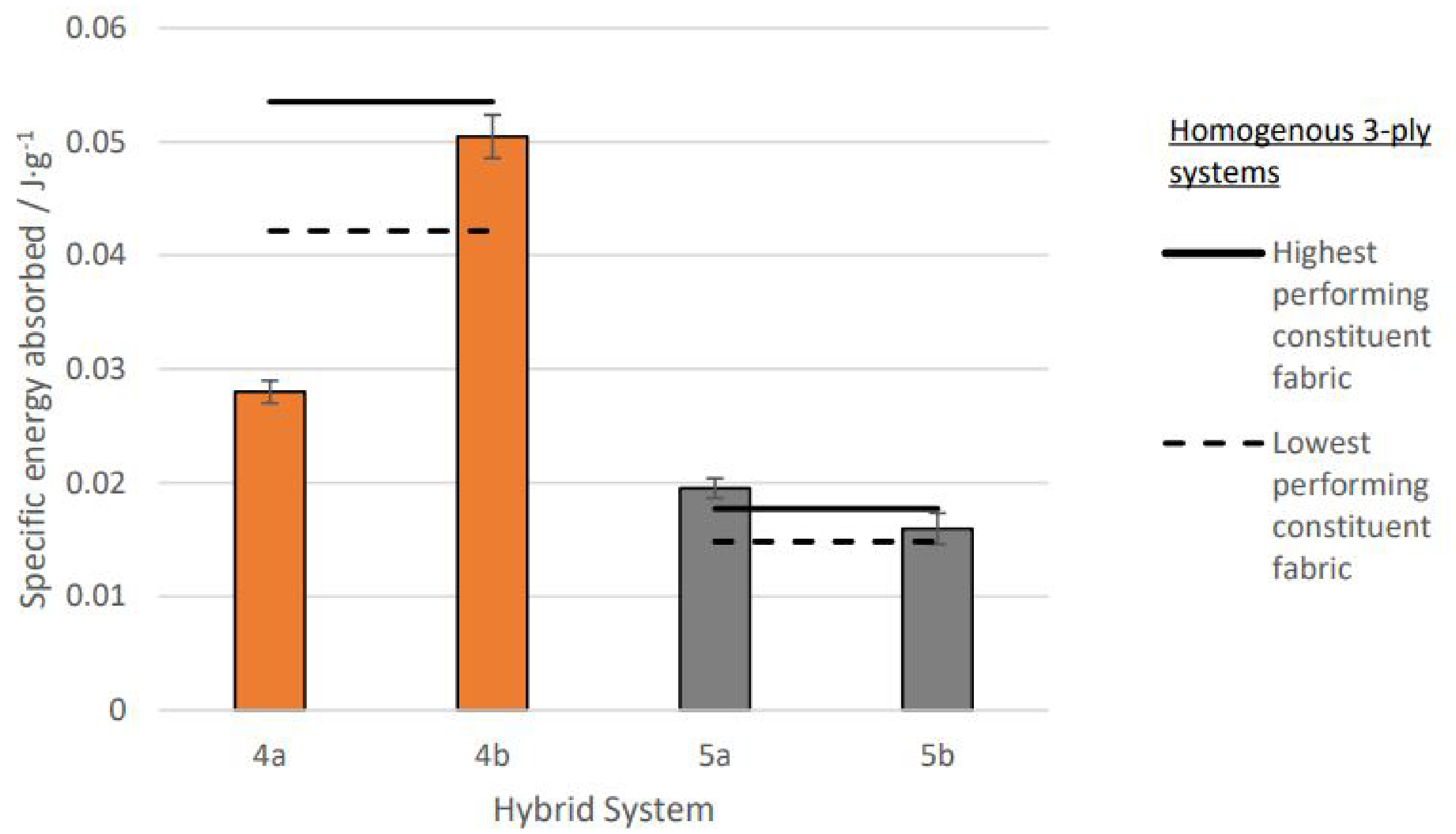
Specific energy absorbed (SEA) of three-ply hybrid systems in the low-velocity regime. Solid and perforated lines indicate SEA of three-ply homogenous systems of the constituent fabrics for comparison. Error bars depict standard errors.
No significant difference was found between either the SK/1760/XX hybrid arrangements in Systems 5a/5b (ANOVA Fcrit = 18.5, P < 0.05). For both triple-ply hybrid systems (4 and 5) there was no significant difference found between the orientations with the highest and lowest SEA and the highest and lowest performing constituent fabrics (CT/550/14 and 4b; CT/550/10 and 4a; 5a and or 5b and SK1760).
Figure 12 shows images from the HSV following the impact of Systems 3c and 3d. For System 3d, where the para-aramid is the strike face and the UHMWPE the rear face, there appears to be increased and prolonged engagement between the yarns and projectile compared to the alternative System 3c, for which the yarns had disengaged by frame 5 following each impact. Given that the para-aramid yarn has a higher coefficient of friction 5 and the CT/840/10 fabric a higher thread count, it is plausible that having the para-aramid on the strike face ensured engagement with the rear UHMWPE ply. The low weave friction and high linear density yarns were factors that had consistently undermined the potential performance of the SK/1760/XX fabrics.
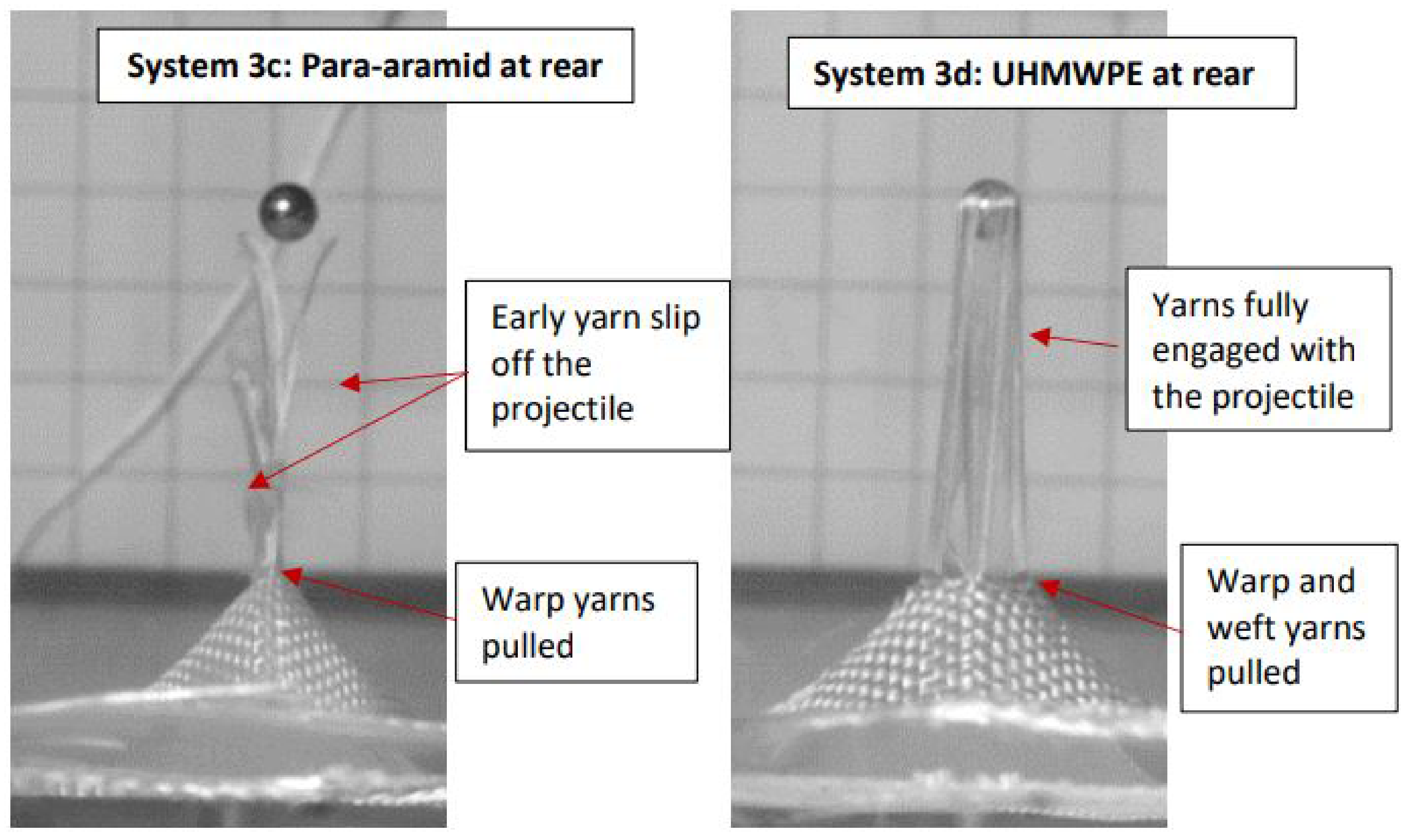
Typical High Speed Video images of Systems 3c (a) and 3d (b) 0.17 ms post-impact. UHMWPE: ultra-high molecular weight polyethylene.
Figure 13 shows the variability in SEA for double-ply hybrid systems in the high-velocity regime with orientation to impact. Like the homogenous systems, the SEA in the high-velocity regime was lower than in the low-velocity regime for all hybrids; there was a mean percentage difference in SEA of 46% across all double-ply systems.
Specific energy absorbed (SEA) of two-ply hybrid systems in the high-velocity regime Solid and perforated lines indicate SEA of two-ply homogeneous systems of the constituent fabrics for comparison. Error bars depict standard errors.
Both para-aramid double-ply systems (1 and 2) showed a higher SEA with the ‘b’ orientation in the high-velocity regime, and only the difference between Systems 2a/2b was statistically significant (Tukey HSD, P < 0.05). The para-aramid/UHMWPE Systems 3c/3d showed no difference with orientation. All double-ply hybrid systems, regardless of layer order, had higher SEA than the double-ply homogenous systems made from their constituent fabrics, which was shown to be statistically significant for all systems except 1a and 1b (Tukey HSD, P < 0.05).
The relative SEA dependent on the layer order of the triple-ply hybrid system in the high-velocity regime is shown in Figure 14. The average SEAs of these arrangements were, again, lower in the high-velocity regime than the low-velocity regime (mean difference 79%).
Specific energy absorbed (SEA) of the three-ply hybrid system in the high-velocity regime. Solid and perforated lines indicate SEA of three-ply homogeneous systems of the constituent fabrics for comparison. Error bars depict standard errors.
In contrast to the low-velocity regime, there was no significant difference in SEA for Systems 4a/4b in the high-velocity regime (Tukey HSD, P < 0.05), where the difference in SEA with orientation was just 6%. For both double- and triple-ply hybrid systems, any effect of orientation on SEA was less pronounced in the high-velocity regime than in the low-velocity regime, suggesting that hybridization may be more applicable at low strain rates and, therefore, work better in the rearward layers of a full-scale system. No additional layer order effects were noted in the high-velocity regime, although the SEA was higher for the hybrid systems than for the homogeneous systems regardless of layer order. The reason for this is unclear from the evidence collected.
In Cunniff’s study 9 of a UHMWPE/para-aramid system, the greater Eabs was found for a two-ply system with a para-aramid strike face and UHMWPE rear face, similar to hybrid System 3d. As the Eabs was calculated from the ballistic limit velocity of the systems, we can assume that the impact velocities were below the critical velocity and, therefore, the hybridized effects would have been as apparent as they were for the systems tested under this research. However, the results of Cunniff’s study were inconclusive. Where originally it was presumed that transverse wave impedance had created the disparity in Eabs with system orientation, this could not be replicated in a double-ply para-aramid system where the constituent yarns were selected to have moduli to cause a mismatch in the strain wave velocity and, correspondingly, the transverse wave velocity. The results do agree with the hybrid systems tested and presented herein. The two para-aramids fabrics used in Cunniff’s study were constructed of similar linear density yarns (1000 and 1079 denier) and thread counts (14.5 × 14.5), which suggests they had similar frictional properties. As such, the orientation of the system would not have shown a variation in Eabs with layer order. In contrast, the para-aramid/UHMWPE system had different linear density yarns and thread counts; the UHMWPE was constructed of 375 denier yarns with a thread count of 19.7 × 20.1 yarns cm−1. The high thread count of the UHMWPE layer mean that the greater Eabs may have been the result of increased yarn engagement and frictional effects in the rear layer, improved contact friction with the projectile on the strike face, or a combination of the two.
Transverse wave propagation: hybrid systems
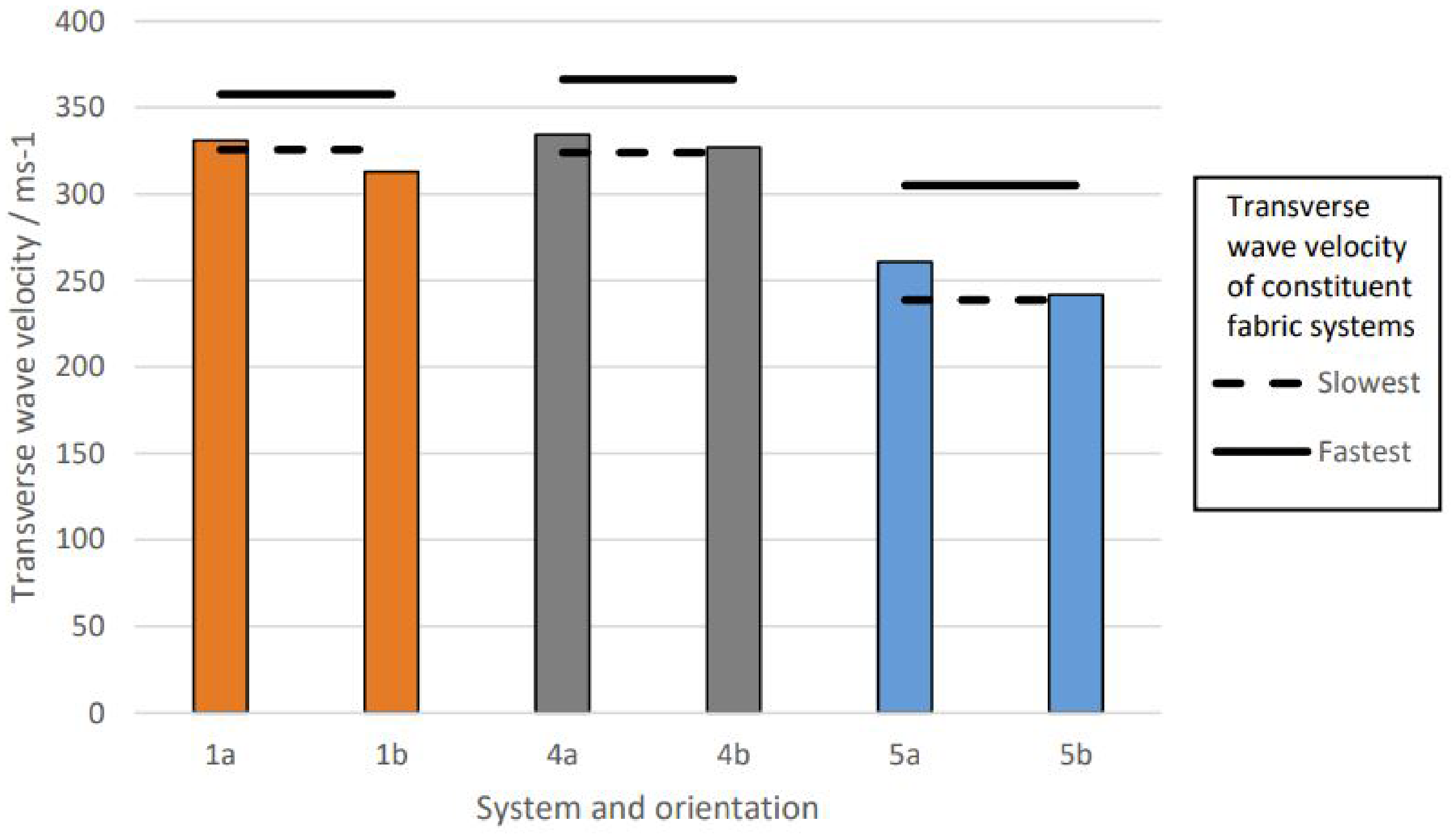
Three of the hybrid systems, Systems 1, 4, and 5 were further analyzed to establish whether the transverse wave velocity varied dependent on the fabric on the strike face of the system. The systems were impacted and stereoscopic images processed as outlined in the second section. Figure 15 shows the transverse wave velocity for these systems in orientations ‘a’ and ‘b’; the perforated and non-perforated lines show comparative data of the homogenous systems of the constituent fabrics with equal ply count.
Transverse wave velocity of hybrid systems.
For all systems, the transverse wave velocity was greater in orientation ‘a’ where the lowest Cfab fabric is located at the rear of the system. Statistical analysis confirms that the difference in the transverse wave velocity was significantly different with orientation for Systems 1a and 1b and 5a and 5b but not for Systems 4a and 4b (Tukey HSD, P < 0.05). In addition, for all systems, the transverse wave velocity of orientation ‘a’ resided between the maximum and minimum velocity measured for the constituent fabrics, while the transverse wave velocity in orientation ‘b’ was approximately equal to or below the minimum value measured for each fabric set. Measurement of the transverse wave propagation confirmed that the wave velocity was slower in systems with the higher Cfab at the rear, proving that the slower waves in the rearwards layers of the system impede the propagation of the transverse wave in the forward layers. This confirmed that the wave propagation through a system can be controlled by selection and placement of fabrics.
Sequencing criteria: hybrid full-scale systems
Initial works by Cunniff9,45 on stacking sequence effects and criteria for determining the stacking sequence of hybrid Kevlar/Spectra systems, further developed by Porwal and Phoenix 21 and Guo and Chen, 46 determined that the transverse velocity played a key role in determining the stacking sequence. In impacted layers, the transverse wave propagates outwards while pulling material in to feed this, creating a transverse cone, with the speed of this cone being an important factor. When the transverse cone of the backing layer grows faster than the strike face layer, both layers can maximize their energy dissipation. When this order is reversed, they found that a faster growing transverse cone layer at the front was inhibited by the slower backing layers, therefore limiting the energy absorbed. These criteria proved to be in agreement with System 3 (para-aramid/UHMWPE), where the two layers had similar Cfab and para-aramid performed best as the front layer and UHMWPE as the rear layer. However, these criteria do not fully take into consideration the effect of weave parameters where a hybridized system is based on varying weave parameters, such as Cfab, which influences the number of yarns in the path, through the system rather than fiber type. In this work, it has been demonstrated that layer interference can prove beneficial to improving energy absorption, where yarn interaction and increased friction effects become more dominant when considering layers of varied weave architectures.
Figure 16 illustrates the suggested layering order for a full-scale hybrid system, based on the fabrics tested, mapped onto a schematic, illustrating the relative energy absorption contributions with impact velocity. The low Cfab fabric manufactured from the high linear density yarn (CT/840/8) would be best placed at the front of a hybrid system. The yarn’s greater tensile strength than the CT/550 yarn ensures a higher Eabs through the work of fracture, whilst the fabric’s low crimp allows the strain to dissipate as quickly as possible along the principal yarns.
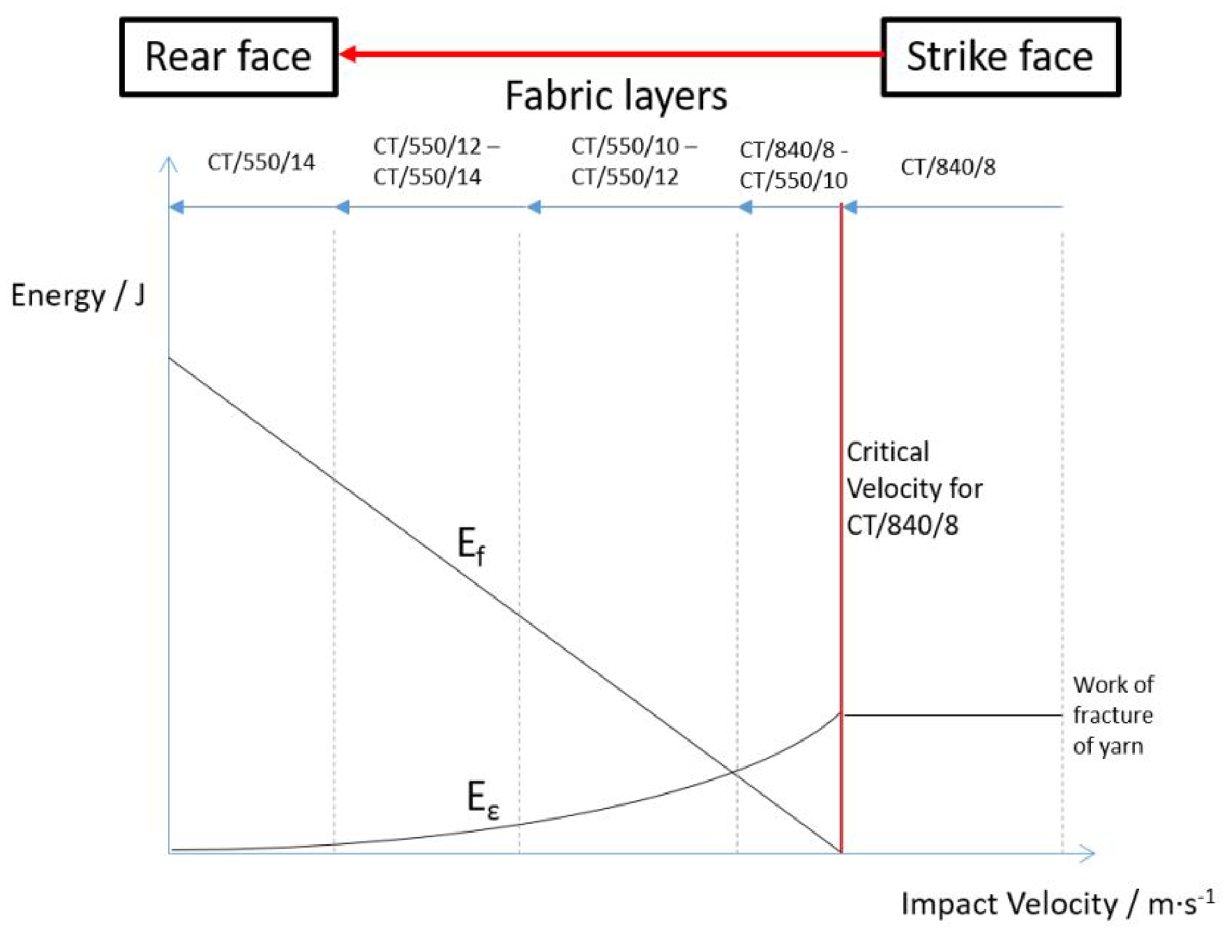
Optimal layering of test fabrics with the theoretical maximum energy that can be dissipated by the system as a function of impact velocity.
Both CT/840/8 and CT/550/10 had a high critical velocity, indicating an early tensile failure mode, allowing the high energy absorbing frictional effects to contribute to the Eabs in as many layers as possible. The CT/840/8 should be placed before the CT/550/10, as the former has a slightly higher critical velocity (455–441 m·s−1) and offers the greater SEA at the highest strain rate, while the CT/550/10 has the better tensile response owing to its higher inter-yarn friction (peak yarn pull: 5.4–3.4 N). The change from one fabric type to the next will depend upon the layer at which the strain drops below the critical level and the tensile failure mode activates; this will not only depend upon the existing layers in the system but also the impact velocity on the geometry of the impacting projectile. As the strain component reduces, toward the rear of the system, the higher Cfab CT/550/XX fabrics should be used to fully exploit the frictional effects, which dominate under that regime.31,47 By placing these fabrics in order of increasing Cfab, the fabric with the maximum inter-yarn friction is selected whilst ensuring the critical strain of the fabric is not exceeded.
Conclusions
The system effects identified for the multiple-ply homogenous systems under both the high- and low-velocity regimes confirm that a soft armor system cannot be considered as a series of individual layers, and the interaction between layers significantly affects the energy absorption capacity. From the homogeneous and hybrid testing, the following was found.
Para-aramid woven fabrics consistently had greater SEA than UHMWPE woven fabrics. System effects were more pronounced in the low-velocity regime, where advantageous effects were promoted when (a) the homogenous systems were constructed of fabrics with high Cfab and low yarn linear density and (b) the hybrid systems had high Cfab and low yarn linear density test fabrics placed at the rear of the systems. In the high-velocity regime, (a) the system effects were reduced and inconsistent and (b) the SEA was greatest in fabric systems constructed from high linear density para-aramid yarns. There was no clear evidence that interference between transverse wave was detrimental or beneficial to the SEA of systems under the low-velocity regime.
Based on the findings from the single-ply and multiple-ply testing to optimize a hybrid system, the following was concluded.
For a hybrid system, para-aramid woven fabrics should be used; the UHMWPE fabrics failed to show any advantage in either velocity regime as single- or multiple-ply systems. Fabrics constructed of low linear density yarns (CT 550 dTex) and high Cfab should be placed at the rear of the system, where the strain is below critical and frictional effects dominate. High linear density yarn (CT 840 dTex) and low Cfab fabrics should be placed at the front of the system, where the strain is above critical. Central layers should be sequenced by increasing critical velocity to ensure those with the highest critical velocity are furthest forward, delaying the failure of individual layers and maximizing Eabs. The optimum hybrid system of the fabrics tested would be, from the strike face to the rear: CT/840/8, CT/550/10, CT/550/12, and CT/550/14 (Figure 16).
Footnotes
Acknowledgements
The authors would like to thank Axis Composites for weaving the test fabrics. Further thanks to Ulster University, Northern Ireland Advanced Composites and Engineering (NIACE) Centre, and DSTL for support and provision of testing equipment.
Declaration of conflicting interests
The author(s) declared no potential conflicts of interest with respect to the research, authorship, and/or publication of this article.
Funding
The author(s) disclosed receipt of the following financial support for the research, authorship, and/or publication of this article: This work was supported by a Department for Employment and Learning (DEL) CAST award supported by DSTL.