
Abstract
Lock-stitch embroidery has been the centre of much interest as a versatile and precise method of producing conductive tracks in the fabrication of wearable electronic devices. However, improper fabrication parameter settings could result in the nonconformity of the conductive tracks and damage the conductive coating of the conductive yarns. In this study, we evaluate the appearance quality, dimensional stability and electrical resistance of conductive tracks by taking into account the embroidering speed (ES), stitch length (SL), needle thread pre-tension (NTP) and embroidering direction (ED). The conductive tracks are embroidered onto knitted fabric in different directions with silver-coated polyamide yarn as the needle thread. The results show that stitching the conductive tracks in the wale direction results in a more uniform stitch lines in comparison to the other directions. To resolve the problem of floated stitches, it is recommended that an SL of 4 mm and a higher NTP are used. The percentage of shrinkage in the wale direction is lower than in the course direction. The electrical resistance of the conductive tracks increases with a higher ES and shorter SL. It is also found that a thicker yarn is more sensitive to the NTP and some of the silver coating is rubbed off with an NTP of 50 gf. We also carry out an overlay plot analysis, through which we predict and validate the optimal embroidery parameters that balance appearance quality and electrical resistance. The technique parameters in this study can be used to embroider conductive tracks for smart clothing.
Keywords
Introduction
Applications of wearable electronic textiles (e-textiles) in smart clothing have attracted considerable attention on account of their immense potential to monitor vital signs in health care situations [1,2], physical performance during sporting activities [3,4], the safety and wellbeing of soldiers and firefighters [5–7], and treatment processes and rehabilitation [8], as well as their role in providing interactive entertainment [9]. Among the different methods to create e-textiles, embroidery is one of the most preferred ways because the technique allows for flexible patterns [10,11], dimensional accuracy, mass production, and cost-effective production. Therefore, embroidery has been widely used to create high-performance textile electrodes [12–15], circuits [16,17] and sensors [18–21].
During the embroidery process, the fabric substrate is held under tension by an embroidery frame that is moved in the x-and y-directions, and an embroidery needle repeatedly pierces the fabric to form stitches. However, the deformation of the fabric during sewing increases the unevenness of the stitch tracks and causes size discrepancies between the embroidered element and the digital design. This not only negatively affects the aesthetics of the product but also results in inconsistent levels of electrical resistance, which severely reduces the performance of wearable e-textiles. A number of studies have therefore investigated the factors that are associated with the accuracy of embroidery pattern elements on woven fabric with digital designs [22–26]. However, while they have shown that the shape and dimensions of the embroidered element fail to conform to the designed digital image in most cases, they use non-conductive embroidery threads. Moreover, even though their work examines embroidery technology, the accuracy of the wearable embroidered devices with conductive yarns has been largely ignored.
Since there is a research gap in fabricating wearable embroidered devices with conductive yarns, it is important to have a good understanding of the type of conductive yarns used for such devices. In the literature, some studies have examined the use of conductive yarns for fabricating wearable devices. For instance, Chui et al. [27] examined silver-coated polyamide yarns for wearable electronic product applications as they are light in weight, and flexible with high mechanical stability as opposed to metal and carbon yarns. They are also widely used in smart clothing as they do not irritate the wearer and are bacteriostatic [28]. Therefore, silver-coated yarns will be examined in this study. However, Chui et al. [27] and de Kok et al. [29] also reported that silver-coated yarns become damaged as the silver is delaminated after stitching during the manufacturing process. The coating of the conductive yarn is damaged after stitching and the damage to the yarns increases in severity from the applied mechanical stresses. That is, conductive thread is subjected to mechanical stresses and strains at different guides, regulated tensions, take-up levers and needle eye sizes during embroidery process. As such, the yarn is damaged that interferes with the electrical resistance performance of the embroidery elements. Therefore, the impact of the fabrication process on the functional performance of silver-coated yarns should be well understood before advancing to the development of e-textiles because it is crucial to preserve the silver that is coated on the yarns during the production process.
As for the type of fabric, knitted fabrics are a good option for e-textiles as they have high extensibility and air permeability. However, embroidering precise wearable devices with conductive yarns on knitted fabric is still challenging. The fabric structure becomes unstable with the application of tensile force, such as when a needle penetrates the fabric [30], which leads to the deformation of the fabric. In turn, this can lead to the nonconformity of the embroidery elements with respect to the designed digital image. Therefore, woven and nonwoven fabrics are usually used in developing electronic wearable devices [13,31,32] in order to produce robust embroidery elements. Nevertheless, even though the effects of the stitch type, stitch length and number of embroidered conductive threads on the resistance of the embroidered lines were compared in [33], little attention has been paid to the impact of the embroidery parameters on the performance of the conductive tracks on knitted fabrics.
Herein, we explore the impacts of the design and fabrication parameters on the embroidery process in terms of the appearance quality, dimensional stability and electrical resistance of conductive tracks. The significance and interactive impacts of the stitch length, needle thread pre-tension, and embroidering speed and directions on the performance of conductive tracks are then evaluated. Also, optimized parameter settings that balance both appearance quality and enhanced conductivity of the conductive tracks are determined. The findings have importance for the embroidery parameter settings of wearable e-textiles, such as electrodes and circuits, which integrate silver-coated conductive yarns into knitted fabrics.
Experimental details
Materials
Two-ply silver-coated polyamide threads (HC 12 and HC 40) were purchased from MADEIRA® [34], and used to investigate the impacts of the embroidery parameters on the performance of conductive tracks. The threads are twisted into 2-ply yarns (see Figure S1 in Supporting Information). The physical properties of these yarns are listed in Table 1. They were tested in accordance with standard ASTM Test Method D204-02.
Physical properties of silver-coated polyamide yarns.

The knitted fabric substrate is certified for producing the T-shirts of firefighters, and supplied by KIVANC GROUP (Istanbul, Turkey). The properties of the fabric substrate are listed in Table 2. The wale and course counts were tested in accordance with ASTM D8007. A cold water soluble film called Avalon (made of polyvinyl alcohol, 20 g/m2) was placed over the fabric surface during the embroidery process.
Properties of the knitted fabric used.

The embroidery machine, JCZA 0109-550 (ZSK Stickmaschinen GmbH Germany) was used with DBX K5 ball-point needles (Groz-Beckert KG Germany), which meant that the needles would not cut fibres and yarns of the fabric substrate.
Methods
A rectangular shaped embroidery pattern that used polylines lines with different angles was designed by using an embroidery software called EPCwin (ZSK Stickmaschinen GmbH). The embroidered tracks were produced along the wale, course direction and four bias angles of 15°, 30°, 45° and 60° respectively. They are symmetric angles based on the course direction (Figure 1). The embroidering process began at the ‘Start’ point in the counter-clockwise direction and after stitching based on shape of the embroidery tracks, and ended at the ‘Finish’ point. Selected embroidered samples are presented in Figure S2 (Supporting Information).

Embroidery test pattern with the studied stitch directions.
The fabrication parameters, including the embroidering speed (ES), stitch length (SL), needle thread pre-tension (NTP) and embroidery direction (ED), were examined for their influence on the conductive tracks. Therefore, a four-factor two-level experimental factorial design was used to consider all combinations of the input parameters (see Table 3 and Table S1 in Supporting Information). Sixteen runs were carried out for each set of experiments. For accuracy and repeatability of the results, the experiments were repeated three times. Therefore, 48 runs were conducted. To determine if there were any data variations in the fabrication process, additional centre points were added in the course and wale directions and repeated four times separately with the following settings: ES (400 RPM), SL (2.75 mm), NTP (40 gf for HC 12 and 30 gf for HC 40) and ED (wale and course). In total, 56 runs were conducted.
Factorial design of selected embroidery parameters and levels for the experiment.

a1 gf = 0.98 cN.
The NTP of HC 12 and HC 40 was set differently because the latter has a lower tensile stress (see Figure S3, Supporting Information). An ordinary polyester thread was placed into the bobbin and the NTP was fixed at 40 gf. The maximum NTP was set in accordance with the stitch formation which kept the interlacing of the needle thread and bobbin thread just below the fabric.
Since the designed embroidery pattern consists of the wale and course directions, the samples were fabricated by using 3 combined input technical parameters. Table 4 presents the simplified embroidery parameters of the 23+1 conductive track samples fabricated with HC 12 and HC 40.
Samples and corresponding experimental specifications.

a1 gf = 0.98 cN.
Characterization of conductive tracks
The performance of the conductive tracks embroidered with silver-coated polyamide thread was evaluated by their appearance quality, dimensional stability and electrical resistance of the running stitch tracks in the wale and course directions respectively. Points A to B in Figure 1 denotes the measured value in the wale direction. Points B to C is the measured value in the course direction.
The appearance quality was subjectively assessed by examining the stitch continuity and uniformity in different directions. The floated stitch numbers at every 10 cm in the wale and course directions on the back side of the sample was used for the statistical (objective) analysis.
The dimensional stability was evaluated by percentage of shrinkage of the embroidered tracks in the wale and course directions, which is calculated by using the following equation:
A scanning electron microscope (SEM, Philips Quanta 200) and an optical microscope (KEYENCE VHX-500F) were used to examine the morphology of the conductive yarns and for the shape image of conductive tracks. A multi-meter (Keithley 2000) was used to measure the electrical resistance of conductive tracks. The length of the embroidered conductive tracks was measured by using a soft tailor tape.
Statistical analysis
Minitab-19 software was used to create the experimental design and carry out the statistical analysis. The influence of the investigated variables was assessed by using the p-value of the two-way analysis of variance (ANOVA) results, in which p < 0.05 shows the significance of each independent variable and the interaction between them.
Results
Evaluation of appearance quality of conductive tracks
All of the conductive tracks were found to be continuous with no broken threads. Figure 2(a) to (l) show the surface morphology of Sample 6 which is embroidered with bias angles in different directions. The figure shows that the appearance of the stitches changes with the embroidering direction. The conductive tracks in the wale direction adhere the most to the design pattern (Figure 2(a) and (g)) while the conductive tracks in the course direction are observed to have serious drift (Figure 2(b) and (h)). The appearance of embroidered conductive tracks can be ordered from uniform to irregular based on the stitch uniformity as follows: wale direction > 60° bias angle > 45° bias angle > 30° bias angle > 15° bias angle>course direction.
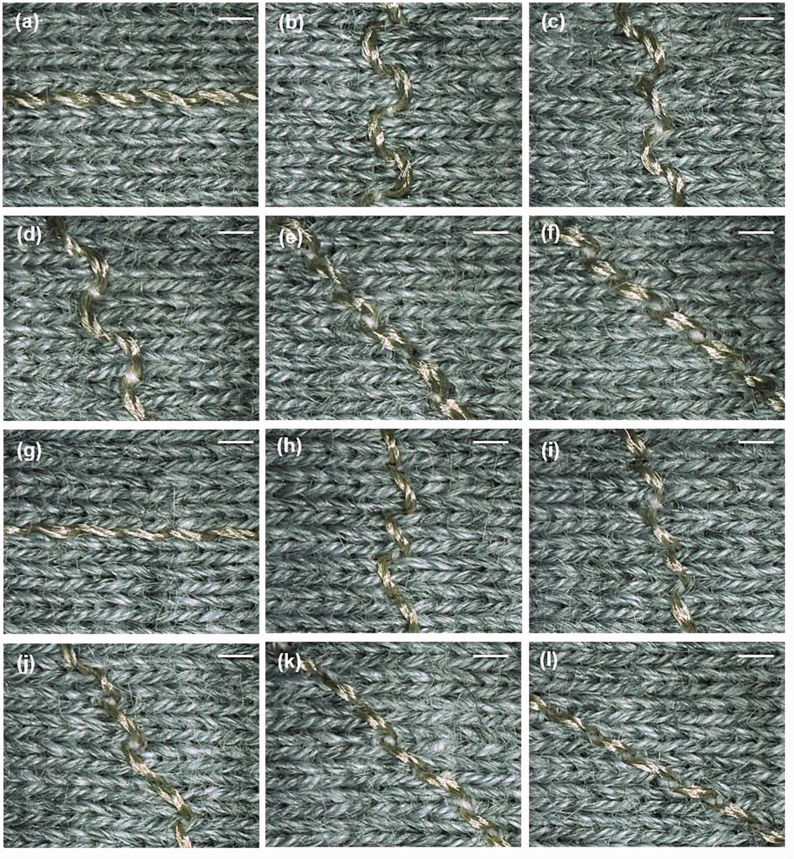
Optical microscope images of sample surface. Scale bars are 1 mm. (a-f) Conductive tracks embroidered with HC 12 thread in the wale direction, course direction, with 15°, 30°, and 60° bias angles respectively. (g-l) Conductive tracks embroidered with HC 40 thread in the wale direction, course direction, with 15°, 30°, 45° and 60° bias angles respectively.
The float stitches were defective as they were obviously loose and twisted on the fabric after the embroidering was carried out, which is the result of the unbalanced thread tension of the needle and bobbin threads. Figure 3 shows the mean floated stitch numbers on the back side of the samples (Figure 3(a) and (b)) and the factors that contribute to the defects (Figure 3(c) to (f)). As shown in Figure 3(a) and (b), the floated stitch numbers in the course direction in most cases is higher than that in the wale direction. Samples 1 to 4 with an SL of 1.5 mm have most of the defective stitches. There are a larger number of floated stitches in the conductive tracks embroidered with HC 12 than in the conductive tracks that use HC 40. Figure 3(c) and (f) show the ranking of the influential factors that affect the float stitches of the conductive tracks embroidered with HC 12 and HC 40 threads, respectively. The number of floated stitches is significantly reduced (from over 3 to 0) with a longer SL and increase in the NTP (Figure 3(d) and (g)). However, the SL has less influence when the NTP is high (Figure 3(e) and (h)). As for the HC 12 thread, the number of floated stitches embroidered in the wale and course directions is also fewer when using a higher NTP and longer SL (Figure 3(e)).

Floated stitch numbers analysis in embroidered conductive tracks. (a, b) Mean of floated stitch numbers on back side for every 10 cm of conductive tracks with HC 12 and HC 40 threads respectively. The upper inset shows a uniform stitch and the float stitch is shown below. Scale bars are 2 mm. (c–e) Statistic results for number of float stitches of samples embroidered with HC 12 thread. (f–h) Statistic results for number of float stitches of samples embroidered with HC 40.
Evaluation of dimensional stability of conductive tracks
The deformation of embroidered fabric increases the nonconformity of the conductive tracks and cause size discrepancies. In order to evaluate the dimensional stability of the embroidered element, the shrinkage (%) of conductive tracks in the wale and course directions was determined. The results can be used to maintain accuracy of the size of embroidered elements through a comparison with the pattern. Figure 4 shows the average shrinkage (%) of samples in the wale and course directions (Figure 4(a) and (b)) and the factors that contribute to this issue. (Figure 4(c) to (f)). It can be observed that there is less shrinkage in the wale direction than in the course direction for all of cases. The shrinkage (%) is significantly influenced by the ED and SL (Figure 4(c) and (e)). However, there is no interaction between any of the parameters. Figure 4(d) and (f) show that with a longer SL, the percentage of shrinkage increases albeit not very significantly (from 4% to over 5%). Note that the lowest percentage of shrinkage of the embroidery in the wale direction is about 3%, while that in the course direction is higher than 6%. Furthermore, longer SL results in an increase in the percentage of shrinkage.

Size shrinkage (%) of embroidered tracks. (a-b)Shrinkage (%) in wale and course directions of tracks embroidered with HC 12 and HC 40. (c-d) Statistic results of samples embroidered with HC 12. (e-f) Statistic results of samples embroidered with HC 40.
Evaluation of electrical resistance of conductive tracks
It is crucial to maintain optimum electrical conductivity when incorporating conductive yarns in the embroidery process. Figure 5 shows the average electrical resistance for each 10 cm of embroidered conductive tracks (Figure 5(a) and (b)) and the factors that affect the electrical resistance (Figure 5(c) to (f)). There is no difference in the electrical resistance in the wale and course directions of the embroidered conductive tracks (Figure 5(a) and (b)). Among all of the test samples, the highest electrical resistance is found with Sample 6, which has an SL of 1.5 mm, the fastest ES and highest NTP. The lowest electrical resistance is found with Samples 3 and 4, which use HC 12, and Sample 7 that uses HC 40 respectively. All of these samples have an SL of 4 mm. Figure 5(c) and (e) show that the SL and ES significantly influence the electrical resistance of embroidered conductive tracks that use HC 12 and HC 40. The NTP also impacts the electrical resistance as of the embroidered conductive tracks that use HC 12. A longer SL significantly reduces the electrical resistance of embroidered conductive tracks, from about 23 Ω/10 cm to 13 Ω/10 cm with the use of HC 12 (Figure 5(d)), and 94 Ω/10 cm to 68 Ω/10 cm with the use of HC 40 (Figure 5(f)). In addition, the electrical resistance increases with a faster ES and higher NTP with the use of HC 12.

Electrical resistance of embroidered conductive tracks. (a-b) Mean of electrical resistance for each10 cm of conductive tracks embroidered with HC 12 and HC 40. (c-d) Statistic results of samples embroidered with HC 12. (e-f) Statistic results of samples embroidered with HC 40.
Trade-off between appearance quality and electrical resistance
The study results show that the appearance quality of the conductive tracks vary in different embroidered directions on the knitted fabric. The number of float stitches increase with a lower NTP and shorter SL. Embroidering in the wale direction not only increases the uniformity of the stitches of conductive tracks, but also reduces the percentage of shrinkage. The electrical resistance of conductive tracks is reduced with a longer SL and slower ES. Regression equations that involve the parameters of the significant factors and their interactions with the performance of conductive tracks were subsequently established and provided in Table 5. The regression coefficients (R2) are also listed.
Multi-linear regression equations based on significant factors.

Notes: A: ES; B: SL; C: NTP; D: ED.
To determine the appropriate embroidery parameters that would allow for conditions of good appearance quality and lower electrical resistance, an overlay plot analysis was carried out. The SL and NTP were set as the decisive factors for the HC 12 and HC 40 threads. The white region of the contour plot shows the best results and related variable values in Figure 6. The acceptable range of electrical resistance values for the conductive tracks is set as one to twofold value of the resistance for each 10 cm of the original conductive yarns. The optimum number of float stitches ranges from –0.5 to 0. Other optimal embroidery parameters are an ES of 200 rpm and stitching in the wale direction. Figure 6(a) shows the optimum range of SL and NTP with the use of HC 12. When embroidering with stitches longer than 3.1 mm, the NTP can be set from 30 gf to 50 gf. An SL that is more than 3.5 mm and NTP setting of 26 gf to 40 gf are suitable with the use of HC 40 (Figure 6(b)).

Overlaid contour plot of minimum number of floated stitches and the lowest electrical resistance per 10 cm. (a) HC 12 thread and (b) HC 40 thread.
Based on the variable ranges obtained from the overlaid contour plot, a multiple response optimization analysis was carried out to establish the factor levels that minimise the electrical resistance value and number of floated stitches. The prediction was carried out by Minitab-19 and the results are shown in Table 6 for both the HC 12 and HC 40 threads. The targets for the upper and lower limits of the electrical resistance value and the number of float stitches were set to be the same as those in the contour plot analysis.
Multiple response prediction of embroidery parameters.

a1 gf = 0.98 cN.
After the optimization analysis was carried out, the variables and their values were validated by carrying out an embroidery test. Each embroidery parameter was used to fabricate 15 cm of straight tracks along the wale direction, and each embroidery test sample was replicated ten times. The electrical resistance of conductive tracks was calculated and the results are all in the range of a 95% confidence interval (CI) of the predicted response results. All of the stitches on the validated samples are uniform with no float stitches. The validated results are shown in Table 7.
Validated results of embroidery parameters.

a1 gf = 0.98 cN.
Discussion
Knitted fabrics have a slack structure and deform with the application of tensile force, and when used for e-textiles, result in the nonconformity of conductive tracks. Audzevičiūtė-Liutkienė et al. [30] showed that there is less non-uniformities of knitted fabrics in the crosswise direction as opposed to the lengthwise direction. The loops of the knitted fabric in the course direction can easily slip when the needle and bobbin threads interlace to form stitches. Also, this study finds that the loop structure of the knitted substrate can be easily distorted by the force of the interlacing of the needle and bobbin threads when the embroidery angle is 15° and 30°. When the embroidery angle is greater than 45°, the loops in the wale direction are more stable and can endure the force during stitch formation. For example, the stitches are more uniform with an embroidery angle of 60°. The density of the fabric structure in the wale direction (35 counts per 2.5 cm) is higher than in the course direction (28 counts per 2.5 cm); therefore, the stitches in the wale direction are more compact and closer together during the embroidery process. Furthermore, a lower density in the course direction results in a larger elongation in this direction, which increases the shrinkage of the embroidered conductive tracks. An analysis by Juchnevičienė et al. [24] showed that it is important to evaluate the changes in size of substrate materials in different directions in order to produce embroidered elements with more accurate dimensions.
Lock-stitch embroidery is versatile because different materials and techniques can be combined and used together, such as padding, shearing, etc. [35]. This technique can produce a ‘two-thread’ structure, and the needle thread passes through the fabric substrate, bends and forms a loop with a small curvature radius when the needle moves upward. This loop is pulled by the rotary hook point, and the bobbin thread is released and wrapped during rotation of the hook mechanism under the needle plate. These two threads interlace below the fabric and form the stitch [36–38]. The key steps to forming a needle thread loop and lock stitches by the rotary hook are illustrated in Figure 7(a). The NTP is the essential factor for determining the interlocking of the needle and bobbin threads. In general, their tension is adjusted so that the bobbin thread is visible on the back side of the embroidery elements [22]. Figure 7(b) shows the formation of a 301 lock stitch with the appropriate amount of pre-tension. The electrical resistance of the embroidered conductive tracks is related to the length of the conductive thread. A longer SL reduces the stitch density, thereby reducing the thread consumption per unit. This lower thread consumption is related to the lower final electrical resistance value of conductive tracks.

(a) Mechanical components of stitch formation in lock-stitch embroidery. Inset: photograph of NTP regulator components. (b) Lock-stitch structure in the embroidery. (c) Load extension curve for HC 12 and HC 40. (d) Optical microscope image of HC 12 and (e) of HC 40. Scale bars are 1 mm.
To validate the bending rigidity of the silver-coated threads, their tensile properties were examined in accordance with standard ASTM Test Method D2256-10 (250 ± 3 mm gage length at 300 ± 10 mm/min operating rate). Compared to an ordinary polyester thread, the silver-coated threads showed a higher initial modulus (Figure 7(c)). The thread at higher level initial modulus is stiff, which is easy to result in floated stitches with improper needle thread pre-tension. Therefore, the number of floated stitches on the conductive tracks embroidered with HC 12 is higher than with the use of HC 40. However, a higher NTP can stabilize the stitch formation and solve this problem. The NTP was adjusted by using three disk tensioners during the embroidery process (Figure 7(a)). The conductive thread became elongated and rubbed the mechanical components which increased the friction with the higher NTP, and subsequently damaged the silver coating on the conductive threads. The silver coating of HC 12 is more sensitive to this abrasion because it is thicker than HC 40 (Figure 7(d) and (e)). Apart from that, as the conductive thread passed through the take-up lever, the needle underwent greater dynamic loading and more friction cycles as the embroidery process was carried out at a high ES, which resulted in more damage to the silver coating of the conductive threads. Most embroidered wearable e-textiles use conductive thread in the bobbin because the thread is subjected to less stress during the manufacturing process [39,40]. However, the conductive tracks are hidden by the frame of the embroidery hoop, which makes it difficult to combine different materials and techniques.
In order to investigate the extent of the damage to the silver coating, the surface morphology of HC 12 before and after the embroidery process was analysed by using the SEM (Figure 8(a) to (d)). The embroidered conductive track of Sample 6, which has the highest electrical resistance was examined. Figure 8(c) and (d) show that the silver coating on the fibre surface is damaged after the embroidering process, which is also confirmed through energy dispersive X-ray spectroscopy (EDX; Figure 8(e) and (f)). There is more than a 20% reduction in the silver atomic content after the embroidering process which could also be the exfoliation of the silver coating on the conductive fibres due to abrasion.

(a,b) SEM images of HC 12 before embroidery processes. (c,d) SEM images of HC 12 after embroidering with 1.5 mm stitch, at 600 rpm, and NTP of 50 gf. (e) EDX analysis of HC 12 before embroidery process. (f) EDX analysis of HC12 after embroidery process. The insets in (e) and (f) are atomic percentage results in EDX.
Conclusion
In summary, we have demonstrated that a uniform appearance of the conductive tracks in fabricating e-textiles would be more feasible if stitched in the wale direction of a single jersey fabric. An analysis of the stitch balance indicates that the number of floated stitches is higher with an SL of 1.5 mm and lower NTP. We have also shown that the percentage of shrinkage in the wale direction is less than in the course direction, and the electrical resistance of the conductive tracks is increased with a higher ES and shorter SL. The EDX results indicate that a thicker yarn is more sensitive to the NTP and some of the silver coating is rubbed off with an NTP of 50 gf. In order to optimize the embroidery parameters for excellent appearance quality and lower electrical resistance, we use an overlay plot analysis to predict the appearance quality and electrical resistance. It is found that an SL of 4 mm and lower ES of 200 rpm comprise the optimum combination of factors due to lower consumption of conductive yarns and mechanical force reduction during the embroidery process, which is validated by conducting further embroidery experiments. The results of the new experiments validate the optimised parameters and we obtain the lowest electrical resistance for the conductive tracks embroidered with HC 12 thread (11.46 ± 0.62 Ω/10 cm). These findings have substantial value for the fabrication of e-textiles such as high-performance circuits and other electrically conductive systems and devices.
Footnotes
Declaration of conflicting interests
The author(s) declared no potential conflicts of interest with respect to the research, authorship, and/or publication of this article.
Funding
The author(s) disclosed receipt of the following financial support for the research, authorship, and/or publication of this article: We would like to acknowledge the financial support from the EU Horizon 2020 program- project code 644268 - ETEXWELD - H2020-MSCA-RISE-2014, and The Cotton Textiles Research Trust for the “Protective Efficiency of Respiratory Protective Equipment against Byssinosis for Cotton Workers” project.