
Abstract
This work was investigated that the effect of aluminium (Al) and copper (Cu) wire mesh embedded as a structural reinforcement on jute epoxy hybrid composite. The hybrid composites were prepared by epoxy LY556 with HY951 hardener as a matrix; jute and wire mesh as reinforcements using the compression molding technique. In hybrid composites, the aluminium wire mesh (AWM) and copper wire mesh (CWM) were embedded as 45° & 90° orientation to the jute fiber (AWM45/90 and CWM45/90). The performance of the fabricated hybrid composites was studied by conducting various mechanical, thermal, and dynamic characterizations. The test results were shown that the tensile strength of the fabricated composite was improved by 14.12% in AWM45 and 9.28% in CWM45 compared to AWM90 and CWM90 composites respectively. The TGA result expressed that the thermal stability of the CWM45 composite was enhanced with the residue of 18.33% at 800 °C due to the influence of Cu-wire mesh. In the transition region, the 45° oriented wire mesh improved the loss modulus (E″) peaks about 31.74% in CWM and 11.49% in AWM composite to 90° oriented mesh.
Introduction
Over some time, the environmental concerns and government laws enforce the manufacturing industries to substitute synthetic material with eco-friendly materials. The composites are manufactured by combining two or more materials to attain the specific property. The composites are categorized based on the matrix and reinforcement [1–3]. The composite material plays a significant role in all the fields of manufacturing industries. In the endeavour to prepare eco-friendly products, natural fibers are employed in the development of composite. Considering all constrains like properties, recyclability, and environmental aspects, the fiber-reinforced polymer composites (FRPC) are highly preferred by the industries [4]. The usage of FRPC is extended to different fields like automotive, aviation, and naval industries due to its high strength and stiffness. Specifically, the automotive sectors are interested in minimising the kerb weight and in reducing the vibration as per the motor vehicle acts and customer expectations. The polymer matrix composites usage was extended towards automobile panel, frame parts, interior parts, dash panels, packaging, household applications, and construction applications [5,6]. In recent days, researchers are focused on different accessible natural fibers composite fabrication.
The natural fibers such as cotton, jute, ramie, flax, banana, sisal, hemp, have their own benefits and shortcomings over others. The natural fiber strength is heterogeneous by nature, and the natural fiber composites hold low density, poor machining, and a high degree of flexibility. In order to address these concerns, the researchers are used different fibers and particle additions in the matrix. The kinds of literature are reported that the enhancements of mechanical properties of the natural fiber composites are achieved by introducing dissimilar reinforcement such as fibers and fillers [7]. The performances of FRPC are estimated through mechanical, vibration, thermal, magnetic, viscoelastic, noise, and machinability to adopt industry applications [8–13]. Industries are paying close attention to hybrid composites due to their vast flexible applications and their better mechanical properties. Usually, the natural fiber composites are developed by single, two, or more fiber combinations. The hybrid composite can be prepared by adding one or more reinforcement in a matrix. The hybridization of jute, Cyperus pangorei, and banana fiber composites enhances the mechanical and thermal properties by reducing moisture absorption [14,15]. The dissimilar laminate stacking arrangement and chemical treatments affect the mechanical properties of different composites [16]. The hybridization natural fiber composite provides superior performance in water absorption than unique natural fiber-reinforced composites [17].
The hybrid composites with jute and waste paper have enhanced the tensile and flexural properties than the mono paper composite. The woven fiber and layering arrangement influence the mechanical properties of the hybrid composites [18]. The fabricated hybrids composite has shown better mechanical properties than the mono composite [19]. The silicon carbide and ferric oxide particle addition in jute epoxy composites increase the void, water absorption, hardness, tensile, flexural strength, and impact strength. Also, this particulate addition diminishes the thermal conductivity of the jute epoxy composite, and ferric oxide composite can be a promising material used for microwave absorber.
Similarly, the particle addition enriched the viscoelastic properties such as E′ and E″ compared with the jute epoxy composite [20,21]. The fiber surface treatment minimizes the moisture absorption and enhances the interlocking between the matrix and fiber reinforcement [22]. Among the natural fibers the jute, kenaf, hemp, flax, and sisal are own better strength, mass production, and adaptability to use in automobile applications [23].
Several attempts are made to improve the matrix toughness by hybridization with different fibers and fillers. The primary concern in the filler reinforcement is the uniform dispersion, clustering, and agglomeration in the matrix. The polymer matrix composite possesses poor structural stability due to its density. In order to overcome the drawback, some structural reinforcements (wire mesh) are embedded in the hybrid natural fiber composites. In some hybrid composites, the metal and natural fibers have been added together with the polymeric resin to enhance the structural stability [24]. The chemical treatment enhances the bonding between the wire mesh and fiber interface. A morphological study also ensures it. In the hybrid composite, the middle layer of wire mesh enhances the mechanical properties of the composite [25]. In the FRPC, the 45° oriented wire mesh shows an increased stiffness, strength, and ductility [26]. The electro polished and etched layer exposed higher interface fracture toughness between the fiber and metal interface [27]. The manufacturing industries were focused on new materials for superior performance, lightweight and economic benefits. People were focused green environment revolution, which leads to green composite research. However, to overcome the few shortcomings in green composite mainly, on the mechanical properties of composite and the heterogenic property of fiber should be accounted for this investigation.
The authors are fascinated to develop a fiber metal laminate for the automotive part manufacturing to keep the eco-friendly environment, lightweight, recyclability, cost, and service life. Some of the researchers previously investigated the effect of steel wire mesh in natural fiber composite [24]. The epoxy resin has been utilized for the composite fabrication due to its significant properties like excellent dimensional, environmental and thermal stability [28]. Generally, the cross-linked epoxy resin has weak impact strength [29]. However, in order to improve the toughness property of the epoxy resin by considering the addition of aluminium and copper wire mesh has been embedded in this work. However, the density of the steel wire mesh enhances the weight of the entire composite specimen. So, to overcome the drawback and the weight to strength ratio is better than the steel wire mesh the author is interested in studying the effect of aluminium, copper wire mesh jute/epoxy hybrid composite laminate through mechanical, thermal, and DMA analyses.
Experimental details
Material and methodology
The woven mat jute fiber is procured from the jute association of India Chennai. The plain weaving jute fiber is having a fiber thickness of 0.5 mm and a woven mat thickness of 0.9 mm with 120 GSM. The epoxy – LY556 resin and hardener – HY951 [23] are used as the matrix. The fine wire meshes of aluminium (AWM) and copper (CWM) with a mean diameter of 483 µm with a mesh grid size of 1084 µm are used as structural reinforcement. A schematic view of the hybrid composite composition, fabrication, and testing is shown in Figure 1. The wire mesh is cleaned in deionised water to remove the rust and dust.

Fabrication and characterization of AWM and CWM composites.
Fabrication
The epoxy resin mixed with a hardener with the weight ratio of 10:1. The combinations of the matrix (epoxy+hardner) and reinforcements (jute fiber/aluminium or copper wire mesh) are arranged with a weight ratio of 1:4. A three-layer of fiber metal hybrid composites are prepared embedded with wire mesh as a middle layer.
The orientations of jute fiber and aluminium/copper wire mesh arrangements are shown in Figure 2. The hand lay-up technique is employed to fabricate the hybrid composites. A compressive load is applied to the composites and allowed to cool at room temperature. The laminate thickness of (3 ± 0.3 mm) is maintained for both AWM and CWM hybrid composites.

Schematic diagram of AWM and CWM composites.
Composite testing
The fabricated hybrid composite specimens are subjected to mechanical, thermal, and dynamic mechanical characterizations. The mechanical characterization is performed through tensile, flexural, impact, and interlaminar tests as per ASTM test standards. The thermogravimetric analyser analyses the thermal characterization of the hybrid composite specimens. Finally, the dynamic mechanical performance of the composite is evaluated by the dynamical mechanical analyser.
Mechanical testing
Flexural test
The flexural strength is determined by the 3-point bending test under Instron UTM 5900. The flexural strength is estimated as per ASTM D790-17 (100 × 12.7 × 3.2 ± 0.23 mm) [30–34] and the prepared specimens are positioned horizontally on two-point supports. The compressive force is applied to the top of the specimen. The maximum compressive or tensile stress can estimate the flexural strength at the extreme fiber on either the compression or tension side of the specimen.
Tensile test
The specimens are prepared using water jet machining to avoid the delamination of the fibers. The tensile test specimens prepared according to ASTM D638-14 standards (165 mm × 19 mm × 3.2 ± 0.23 mm) [30–34] and the tensile tests are performed by the Instron-8801 Universal Testing Machine (UTM) with the uniform crosshead speed of 2 mm/min along with 2 N rating load cell.
Impact test
The impact strength of the hybrid composite material can be evaluated by conducting the impact test. The test specimens are prepared according to ASTM D256-10 (64 mm × 12.7 mm × 3.2 ± 0.23 mm) (Figure 3) standards, and the test is conducted to determine the ability of the composite to absorb energy during fracture [24].

Schematic diagram of impact specimen.
Interlaminar test
The interlaminar test specimen was prepared using symmetric [450°C/90°C] oriented lay-up with a set of 900°C/900°C plies at the mid-plane. The ASTM D5528-13 standard was used for the interlaminar specimen preparation. The dimension of the specimen was kept with a nominal thickness of 2 h = 3 mm, specimens of length 250 mm, and width 25 mm. The specimens were machined in the fiber direction using the milling machine. The initial crack length was kept a0 = 25 mm. An initial pre-crack of 2–3 mm was maintained, and an adhesive Teflon insert was applied on the mid-plane to serve as a delamination initiator. The specimens were tested in a Universal Testing Machine, with an applied load of 2 mm/min. The interlaminar test is performed to calculate the interlaminar strength of the composite in the through-thickness direction rather than in-plane direction.
Dynamic mechanical analysis (DMA)
The DMA analysis is used to determine the viscoelastic behaviour as storage modulus (E′), loss modulus (E″), and damping factor (Tan δ) of the hybrid composite. The Inkarp Japan (DMS 6100) machine is employed to estimate the dynamic mechanical behaviour of the composite. The viscoelastic performance was analysed in three different regions like the glassy region, transition region, and rubber region under 1 Hz frequency with the operating temperature range of 35–150°C [24]. The specimens oscillate in the sinusoidal force and permits deform within the viscoelastic region, and the three-point bending technique is used with a heating rate of 2 °C/min. Finally, the test specimens are allowed to cool down in the liquid nitrogen environment.
Thermo-gravimetric analysis (TGA)
The thermal behaviour of the hybrid composite is determined though the thermo-gravimetric analyser (SDT Q600 V20.9 BULID 20). The test samples (4–7 mg) were placed in a platinum pan and heated up to 900 °C at a rate of 10 °C/min under nitrogen purge (20 mL/min). The data are acquired with the help of pyris software. Through TGA analysis the weight loss and temperature differences are estimated.
Scanning electron microscope (SEM) analysis
The interfacial properties like internal crack, fiber pullout, and voids of the fractured hybrid jute fiber composite are analyzed through a scanning electron microscope on the cracked surface. All the specimens are coated with a conductive material before the SEM analysis. The accelerating voltage of 15 kV is used for capturing the images under SEM (Carl Zeiss; Model: EVO MA15). The location of fiber pullout, fiber fracture, fractured wire mesh, fiber epoxy mixture, and voids in various locations of the hybrid composite is analysed through SEM under different magnifications (50–300X).
Results and discussion
Mechanical performance
The mechanical performance such as tensile, flexural, impact and interlaminar tests are performed on the fabricated jute/AWM/CWM/epoxy hybrid composite specimens as per the ASTM standard. In each test, three samples are analyzed, and the standard mean values are documented.
Flexural
The maximum load-bearing capacity is observed on the AWM45/CWM45 composite Figure 4(a) and similarly, it provides the maximum elongation of 14.3 mm (AWM45) and 8.3 mm (CWM45) Figure 4(b). The result shows that the AWM45 composite is having maximum elongation than CWM45 due to the physical and mechanical properties of the aluminium wire mesh.

Flexural behaviour of AWM and CWM composites. (a) Ultimate load and (b) deflection.
The circumferential stress of the hybrid composite has been reduced because of the aluminium wire reinforcement at the laminate centre. The 45°oriented wires have shown better flexural strength than 90° oriented wire mesh on both the materials. The aluminium wire mesh shows relatively lower flexural strength than the copper wire mesh and the orientation angle plays a significant role in both the wire mesh. The maximum flexural strength is observed in CWM45 composite this may be primarily due to the bonding strength between the matrix and the angle of the wire mesh orientation
Tensile
The tensile test result indicates that the ultimate tensile strength of 24.2 MPa and 3.33% of elongation is observed on AWM90 composites and 35.96 MPa and 1.67% of elongation is observed on CWM90 composites Figure 5(b) and (c). Figure 5 has shown that the AWM45 and CWM45 composite have shown better tensile strength and elongation than AWM90 and CWM90 composites. Subsequently, the better elongation (3.92 mm) is obtained in 45° oriented aluminium wire mesh composites than the 90° oriented Al (3.33 mm) and Cu wire mesh composites (1.67 mm). The ultimate tensile and yield strength of the CWM45 composite is superior to the rest of the composites due to the lower strain energy and higher density of the copper wire mesh Figure 5(a). The orientation of wire mesh plays a vital role in the resistance of the tensile force in the copper wire mesh composite.

Tensile properties of AWM and CWM composites. (a) Yield strength, (b) ultimate tensile strength and (c) elongation.
Impact
The obtained impact strength results reveal that the AWM45/CWM45 composite absorbs more energy than the AWM90/CWM90 composites (Figure 6). The fiber weaving distance and the ductility of the aluminium wire mesh comparatively higher than the copper wire mesh composite which enriched the flexibility of the 45° oriented aluminium wire mesh composite. However, the 45° oriented aluminium and copper wire mesh play a significant role to minimize the crack propagation during impact force which primarily enhanced the impact strength of the AWM45/CWM45 composites. The reinforcement of the aluminium wire mesh has maximized the energy absorption characteristics of the AWM45 composite than the copper reinforced composites (CWM45 and CMW90).
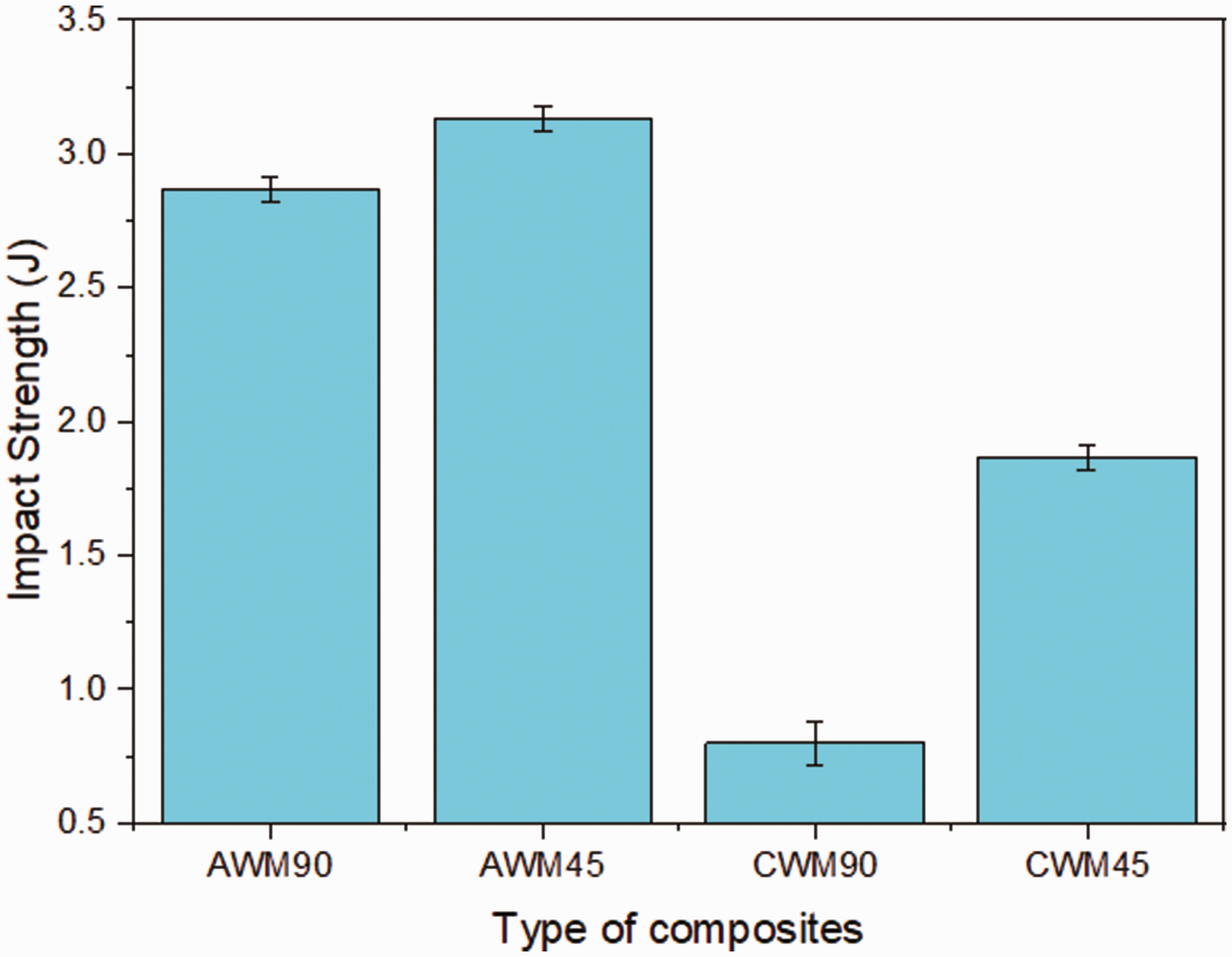
Impact strength AWM and CWM composites.
Inter delamination
The interlaminar strength between the matrix and the fiber metal mesh laminate (aluminium or copper) has determined by the interlaminar test. The interlaminar strength majorly depends on the adhesive and wettability between the fiber, wire mesh, and epoxy resin. However, the interlaminar strength of the AWM and CWM specimens is significantly increased by the influence of Al and Cu wire mesh reinforcements. Figure 7(a) has shown that the CWM45 composite specimen withstand more ultimate stress than the other composite specimens. The interlaminar strength of the 45° oriented aluminium wire mesh composite (AWM45) has shown better results than the rest of the composites (Figure 7(b)). Very high interlaminar stress can arise locally at geometrical discontinuities like 45°, and 90° orientation of the aluminium and copper wire mesh and these may cause failure even though the overall stress level was not unduly high. The discontinuous orientation plies caused by ply joins or by aluminium and copper materials within the layup produce discontinuities analogous to transverse cracks. These are particularly severe if the cut is perpendicular (90° orientation) to the fibre direction in which the significant loads are carried, and can be a critical source of delamination. Whereas, in the 45° oriented wire mesh, the discontinuous plies were not perpendicular to the fiber direction, which primarily enhanced the interlaminar strength of the composite. The microstructural image of the interlaminar shear strength of the 45° and 90° oriented AWM and CWM composite has shown in (Figure 8). The 45° oriented CWM composite has shown better bonding between the jute fiber and copper wire mesh. The 45° oriented AWM composite has shown a substantial decrease in the significant peak load. The complete resistance to inter delamination was observed in CWM45 than the AMW45 composite. The transverse tensile cracks were observed at the bottom layer of the laminate due to high tensile stress.

Interlaminar behavoiur of AWM and CWM composites. (a) Ultimate stress, (b) delamination of composite.

Delamination images AWM and CWM composites (a) Al wire mesh 45°. (b) Cu wire mesh 45° composite.
DMA
The dynamic mechanical performance of the hybrid composites is analyzed in three different regions like the glassy region, transition region, and rubber region under 1 Hz sinusoidal force with different operating temperatures [24].
Storage modulus (E′)
The energy storage capability of a hybrid composite is influenced by the storage modulus (E′). Below the glass transition temperature, the storage modulus is high due to its solid-state and enough interlocking between the molecules. The orientation and material type affect the storage modulus of the hybrid composite. Among all four composites, the CWM45 got higher storage modulus due to the density of copper mesh and orientation and AWM90 holding lower storage modulus in the glassy region. In the glassy region, the orientation (45°) enhances the storage modulus (Figures 9 and 10) in the CWM45 and AWM45 hybrid composites as 45.38% and 32.74% improvement than the 90° orientation samples (Table 1). After the transition temperature, the increase in temperature causes a sudden drop in the storage modulus (E′) and this change due to the rheology phenomena between the fiber and reinforcement [24]. In the rubbery region, the CWM45 composite has recorded maximum storage modulus and minimum in AWM90. It is closely associated with the molecular mobility in AWM90 composite. The CWM45 improves 37.41% of the loss modulus (Figure 9) compared to that in CWM90 (Figure 10).

Storage and loss modulus on AWM 45 and CWM 45 composite.

Storage and loss modulus on AWM 90 and CWM 90 composite.
Dynamic mechanical performance of wire mesh composite.

Loss modules (E″)
The composite materials are used in different temperature and pressure environments. Hence, the findings of damping property play a vital role in the design and manufacturing industries. The energy dissipation in terms of loss modulus of the fabricated composite is determined from the graph as a function of temperature [24]. In the glassy and transition regions, a notable enhancement is observed in loss modulus (E″) for CWM45/CWM90 than the AWM45/AWM90. In the transition region, the peak energy dissipation performance is observed in CWM90 and AWM90 samples. It may occur due to the orientation of the wire mesh and the fiber. In the transition region, the 45° oriented mesh improves the loss modulus about 31.74% in CWM, and 11.49% in AWM (Figures 9 and 10) compare to 90° oriented mesh. A similar kind of performance is observed in the rubber region for copper and aluminium reinforced hybrid composites.
Tan δ
The tan δ is obtained from the ratio of loss modulus and storage modulus. The tan δ expresses the relation between energy dissipation and energy absorption of the material. The interlock phenomenon between the fiber and the wire mesh is noticeably exposed in the curve of different composites (Figure 11) [19]. The change of mesh orientation from 45° to 90° in hybrid composites obtained the improved tan δ values (Al-16% & Cu-11%), and this is due to the effect of storage modulus for 90° mesh orientation. The impact of the wire mesh orientation reduces the damping factor (Figure 11). This impact implies better intermolecular bonding (fiber/mesh/matrix), good load-carrying ability, and less molecular movement, which tends to decreases the damping factor of AWM45 and CWM45 composites. This effect leads to a reduction in tan δ peak and also widens the damping cure compare to 90° mesh angle composites are observed. The enhancement of molecular mobility is noticed in the rubber region for all AWM composite materials, which leads to a reduction in the damping factor.

The damping factor of AWM and CWM composites.
TGA
The percentage of degradation predicts the thermal performance of the composite. The figure depicts that the increase in temperature reduces the weight percentage of the composite during the test (Figure 12). The initial weight of the composite is reduced due to the evaporation of the moisture content in the specimen [30–34]. The temperature rise (28 °C to 220 °C) loses its weight of 2.280% in AWM90 and 2.356% in AWM45 samples. Subsequently, the weight is decreased to 2.117% in CWM45 and 2.281% in CWM90 samples. The weight reduction of hybrid composites is due to the degradation of fiber and epoxy with an increase in temperature. All the four composite materials are drastically degraded between the temperature range of 220 °C to 450 °C due to the burning of the matrix and fiber. The CWM composite has more thermal resistance than the AWM composite since the difference in the melting point of the wire mesh. The minimum quantity (8.819%) of residue is obtained for AWM90 composite and the maximum obtained for CWM45 after 800 °C temperature. It is due to the degradation of aluminium wires faster than the copper wires. The obtained results revealed that CWM specimens are having more thermal stability than the AWM specimens.
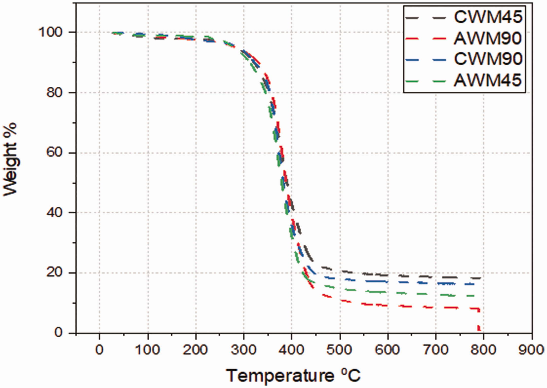
TGA analysis of AWM and CWM composites.
SEM analysis
The micrographs (Figure 13(a) and (b)) of the AWM45 and CWM45 composites reveal the fiber/wire mesh failure during the tensile and flexural tests. The wire mesh orientation results in higher anisotropic mechanical properties in both directions, i.e. the wire mesh normal to the fiber orientation, and the other one is at 45° to the fiber orientation. The 45° oriented wire mesh (Figure 13(a) and (b)), has shown that the crack was found to grow in a zig-zag form [19].

SEM images of (a) AWM45 (b) CWM45 specimen (c) CWM90 and (d) AWM90 specimens.
Whereas, the 90° oriented wire mesh results in the cleavage mode of fiber/mesh failure (Figure 13(c) and (d)). The interface de-bonding, wire mesh fracture, and fiber pull-out were also analyzed from the fracture surface. Figure 13(c) indicates the shear mode of failure on the 90° oriented AWM composite whereas; it was minimum in 45° oriented AWM45 specimen Figure 13(a). It was observed that in a few regions, a small amount of fiber pullout and fiber breakage was found, which indicates there is a reliable interface between the fiber and matrix.
Conclusion
The effect of the aluminium/copper wire mesh on jute/epoxy hybrid composite was estimated through mechanical, thermal, and dynamic mechanical analysis. The authors were interested in concluding the following points from the results. The ultimate tensile strength 24.2 MPa and 3.33% of elongation were observed in the AWM wire mesh composite, and 35.96 MPa and 1.67% of elongation were recorded in the CWM wire mesh composite. The inclusion of the copper wire mesh maximised the energy absorption characteristics in CWM45 composite than aluminium reinforced composites (AWM45 and AMW90) The rise in temperature from 28°C to 220°C minimized the weight of around 2.280% in the AMW90 composite and 2.356% in the AWM45 composite. In the glass region, the storage modulus was an improvement in CWM45 (45.38%) and AWM45 (32.74%) hybrid composites than the other composite. In the transition region, the 45° oriented mesh composite improves the loss modulus peaks about 31.74% in CWM, and 11.49% in AWM compares to 90° oriented mesh composite. In the transition region, the angle orientation and mesh material play a significant role in the raise of tan δ peaks of AWM90 and CWM90 compared with AWM45 and CWM45 composites.
The results evidence that the CWM45 hybrid composite performs better than the other composite sample in overall aspects. The proposed composite can be adopted for different automotive applications such as small body panels, door panels, cup holders, scratch guards, etc.,. This work can be extended by the addition of different particulate reinforcement, structural reinforcements, and coating on the proposed composites.
Footnotes
Declaration of conflicting interests
The author(s) declared no potential conflicts of interest with respect to the research, authorship, and/or publication of this article.
Funding
The author(s) received no financial support for the research, authorship, and/or publication of this article.