
Abstract
Adding different reinforcements to the polymer composite is gaining more importance in the manufacturing industries because of their variation in mechanical properties. To satisfy modern industrial requirements, the mono-fiber polymer composites are substituted by hybrid composites in civil and automotive applications. The present work is to develop and investigate the hybrid composite behavior reinforced with AISI 304 (500 µm) wire mesh and jute fiber with epoxy LY556 resin. To analyze the mechanical properties of hybrid composites, two different orientations (45° and 90°) of wire mesh are selected and stacked with jute fiber by hand lay-up method. The wire mesh composite or hybrid composite is subjected to mechanical characterization like tensile, flexural, impact, and interlaminar. Subsequently, the viscoelastic behavior of the wire mesh composite is observed in terms of storage modulus (E′), loss modulus (E″), and damping factor (tan δ) by the dynamic mechanical analyzer (DMS 6100). The fractured surface microstructure of the wire mesh composite is analyzed by scanning electron microscope. The 45° oriented wire mesh composite sample shows better mechanical properties in ultimate tensile strength (20.55 MPa), flexural strength (0.145 kN), percentage of elongation (2.83%), and interlaminar strength (0.120 kN). At the transition region, the peak energy absorption of 0.622 is observed in the 90° oriented wire mesh composite sample at 0.5 Hz frequency.
Keywords
Introduction
Composite materials are the most preferred material for the engineering industries due to their adaptability and their desirable properties for specific application. A wide range of materials are combined to form a composite in the past decade. Among them polymer matrix, metal matrix, and ceramic matrix composites are popular due to their high strength-to-weight ratio than the conventional engineering materials. The reinforcement type and size influence the physical and mechanical properties of the composite materials [1].
Now a days people are interested to develop socially benefited polymer composite materials in order to overcome the drawbacks of synthetic fiber composite. In this aspect, the natural fiber composites are viable solution to minimize/eliminate the ill effects of synthetic fiber composites [2] in structural applications. These composites are the appropriate materials for lightweight applications because of their low density, high mechanical properties, and reduced manufacturing and material costs [3–5]. The natural fiber composite materials got a greater interest to use in automobile, construction, household things, aerospace, and other general purpose applications than bulk materials [6–8].
The civil and automobile sectors are majorly benefited by the drastic growth and consumption of natural fiber composites [9,10]. Especially the automotive industries are enthusiastic to introduce lightweight and cost-effective techniques to fulfill their customer’s requirements. The automotive original equipment manufacturers are interested to incorporate natural fiber composite parts for their vehicle to satisfy the modern challenges like emission regulations, fuel efficiency, cost saving, and aesthetics. In addition to that, the consumers are also assessing the vehicle quality through safety and comfort aspects.
Considering these positive aspects, the researchers are motivated to enhance the natural fiber composite properties such as mechanical, thermal, magnetic, viscoelastic, vibration, acoustic, and machining property to match the current requirement and expectation [11–17]. Comfort and safety of the automobiles are influenced by the key factors like thermal, vibration, noise and harshness [18]. The polymer composites are having their tailorability to satisfy the modern requirements. The natural fiber composites are developed in the form of beams, laminate plates, channels, and boxes by using the fibers (non-woven/woven), fillers reinforced with resin [19]. The compression molding, vacuum infusion, film stacking, filament winding, injection molding, hand lay-up, and pultrusion techniques are used to produce natural fiber composites. The hand lay-up is one of the popular techniques [19–21].
The physical properties of natural composites are enhanced by different techniques. Despite various techniques, hybridization is a popular technique to meet the automotive industry requirements like lightweight, strength-to-weight ratio, and vibration damping, without compromising the strength of the composite. In natural fiber composite development, the epoxy resins are generally preferred because of their high strength due to less shrinkage, nontoxic, and low cost [22–24]. Among the various natural fibers, jute is one of the important commercial fibers followed after cotton.
Jute fibers are having diversified uses like covering, binding, and textile applications. From the literature review it has been proved that the jute composite is suitable for property enhancement and commercialization for various engineering applications [25]. The jute fibers are widely preferred for various engineering applications due to its mass production, low cost and high strength [26]. The jute fiber’s chemical and mechanical properties are presented in Table 1. The use of jute composites is limited because it has high water absorption and temperature resistance properties. The chemical treatment of jute fiber increases the mechanical properties, stiffness, and thermal behavior [29,30].
Chemical composition and mechanical properties of jute fiber [27, 28].

Perhaps the natural fiber alone is not suitable for various applications due to the nonstable properties and it can be overcome by the hybrid/sandwich composite. The drawbacks of mono-fiber natural composites are eliminated in hybridization technique. In hybrid composite, the combining of fibers, wire mesh, and the type of stacking sequence are added advantages in property enhancement which is very much suitable for automotive and construction applications. The differences in stacking sequence of woven fibers in hybrid composites enhance the mechanical and vibration characteristics [31]. Also, the hybridization improves the dynamic mechanical properties [32,33]. The properties such as storage modulus, loss modulus, and damping factor are examined through dynamic mechanical analysis (DMA) [34]. The storage and loss modulus increases with hybrid sisal/glass fibers with polyester [35]. The viscoelastic properties such as storage modulus (E′), loss modulus (E″), and damping (tan δ) are examined in the temperature range of 30–200°C. In hybrid composite, the viscoelastic properties (E′, E″, and tan δ) are maximum due to the better adhesion between fiber and matrix for higher percentage of jute fiber. The higher jute fiber loading in the hybrid composite increases the glass transition temperature [36]. The increase of fiber loading in composite enhances the storage modulus. Due to the matrix fiber adhesion, the glass transition temperature increases to the higher value [12].
Primarily, a few works are found in the reinforcement of the composites with stainless steel wire mesh [37]. Considering all the aspects, the authors’ enthusiasm is to develop hybrid composite for automobile application. Subsequently, the effects of steel mesh on jute/epoxy hybrid composites are obtained by mechanical characterization and viscoelastic behavior. The mechanical characterization is performed experimentally to assess the tensile, flexural, impact, and interlaminar properties. The viscoelastic behavior is evaluated by DMA. Finally, the fracture surfaces are selected for analyzing the behavior between the fiber/wire mesh and the matrix by scanning electron microscope (SEM).
Experimental analysis
Fiber and materials
The woven jute fiber is procured as mat form from Jute Association of India, Chennai with a fiber thickness of 0.3 mm. The 1.5 mm2 304 steel wire mesh with 500 mm wire diameter is used as structural reinforcement. LY 556 and HY 956 are selected as resin matrix and hardener, respectively, for the composite preparation.
Composite preparation
The fabrication of composites is carried out in mold of size 400 mm×400 mm×8 mm glass plate. The sticking ability between glass mold and composites is prevented by the application of release agent on the mold surface. Woven jute fiber and wire mesh are prepared to the size of 300 mm × 300 mm and stacked in the sequential order of jute/stainless steel mesh/jute (Figure 1). The epoxy resin is weighed to maintain the ratio of 60:40 with jute fiber/stainless steel wire mesh for both orientations (90° and 45°). The ratio of 10:1 (as per the manufacturer’s recommendation) epoxy LY 556 resin is mixed with a hardener (HY 956) in weight percentage and applied over the jute and steel mesh for every stacking. The hybrid composites are fabricated by hand lay-up technique. Utmost care is taken in fabricating the composites, the thickness of the composite not to exceed 3 ± 0.6 mm. The fiber/mesh stacking sequence and the orientations (90° and 45°) are shown in Figure 1. The composites samples are cured by applying a compressive load of 200 kPa with a solid mass and then it is allowed to cure at room temperature for 24 h.

Schematic of fiber and steel mesh orientations in hybrid composite.
Mechanical characterization
The hybrid composite mechanical behaviors are assessed by tensile, flexural, interlaminar, and impact test. The specimens are prepared as per the ASTM standards using abrasive water jet machining to avoid the excessive force and delamination of fibers. Subsequently, the fractured surfaces are assessed by SEM to understand the microstructural behavior of the composite.
The tensile property of the hybrid composite is determined by universal testing machine loaded at a uniform crosshead displacement of 3 mm/min and mounted with 2 N rating load cell. The test specimens are prepared (165 mm × 19 mm × 3.4 ± 0.35 mm) according to tensile test standard ASTM D638 (Figure 2). The specimens are loaded up to the rupture point to estimate the ultimate tensile strength at room temperature.

WMC tensile sample.
The measurement of flexural strength is a complex one. During the assessment of flexural strength, different stresses are acting on top (compression stress), bottom (tensile stress), and middle (shear stress) of the specimen in three-point bending [24,30]. The test specimens are prepared [24] as per the ASTM D790 (100 mm × 12.7 mm × 3.5 mm) standard (Figure 3). The universal testing machine is also used to assess the flexural strength of composite.
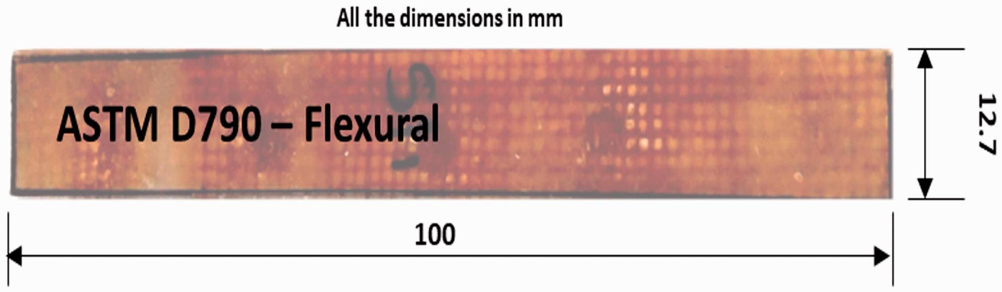
WMC flexural sample.
Engineering materials are subjected to impact loading at different processes like machining, drilling, etc. This effect develops the internal stress in the form of delamination, cracking, and fiber fracture in the composite. The toughness of the hybrid composite is assessed by the impact testing machine and the test specimens are prepared [24] as per ASTM D256 (Figure 4).

WMC impact sample.
The interlaminar shear strength (ILSS) test is conducted on three specimens of each type laminate as per the ASTM D2344/D2344M-16. The three-point bend test is conducted on the Instron 8801 machine using a crosshead tensile force at a constant loading speed of 1 mm/min and unloading speed of 2 mm/min. The displacement of the specimen is recorded against the applied load. The Juravski formula is used to determine the ILSS. It says that when the beam of rectangular section is subjected to a three-point bending, the maximum interlaminar shear occurs at the mid of the span.
DMA
The dynamic mechanical properties of wire mesh composite (WMC) are analyzed using dynamic mechanical analyzer (Inkarp Japan (DMS 6100)) at the glassy, transition, and rubber regions. The test specimens are prepared as per ASTM D 5023 with the dimensions of 50 mm × 13 mm × 3 mm [24,35]. Experiments are performed in the temperature range of 30–200°C with a heating rate of 2°C/min and an operating frequency of 0.2–5 Hz. The viscoelastic properties like storage modulus (E′), loss modulus (E″), and damping factors (tan δ) are measured as a function of time and frequency. The stiffness is an important feature for the engineering material which emphasizes the energy storing characteristics during different loading condition and it is estimated by the term storage modulus (E′) [24].The fiber matrix epoxy composites are having elastic property and the rise in temperature affects the viscoelastic behavior. The energy dissipation is maximum in the transition region and it is represented by loss modulus (E″) [38].
SEM analysis
The composite specimens are thoroughly cleaned and the dust particles are removed for better microstructural image. All the specimens are coated with a thin conductive material (silver) that enables high-resolution images through SEM. The microstructural and fracture surfaces of the WMC samples are examined using a SEM with an accelerating voltage of 15 kV using (CARL ZEISS; Model: EVO MA15). The SEM image reveals the appearance of fractured wire mesh, fiber pullout, fiber fracture, fiber epoxy mixture, and voids in various locations of the hybrid composite under different magnifications (30×, 100×, 150×, and 270×).
Results and discussion
Mechanical characterization
The yield strength of a material can be determined by the stress–strain diagram. Table 2 lists the ultimate tensile strength, percentage of elongation, and yield strength values for the two different orientations of WMCs.
Tensile properties of the WMC samples.

WMC: wire mesh composite.
Figure 5 shows the load versus displacement curves for differently oriented WMCs. A maximum elongation of 2.83 mm is observed in 45° oriented WMC at 0.74 kN load, whereas 1.43 mm is observed in 90° oriented WMC at 0.62 kN load. From the tensile test results it is found that the tensile strength and elongation of 45° oriented WMC showed a higher magnitude than 90° oriented WMC.
Tensile behavior of WMC samples.
The flexural strength is an important property for a material to measure its bending forces, which is applied perpendicular to its longitudinal axis. The flexural properties of WMC for different orientations (45° and 90°) are summarized in Table 3.
Flexural properties of WMC samples.
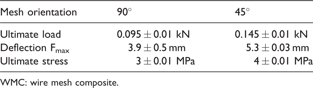
WMC: wire mesh composite.
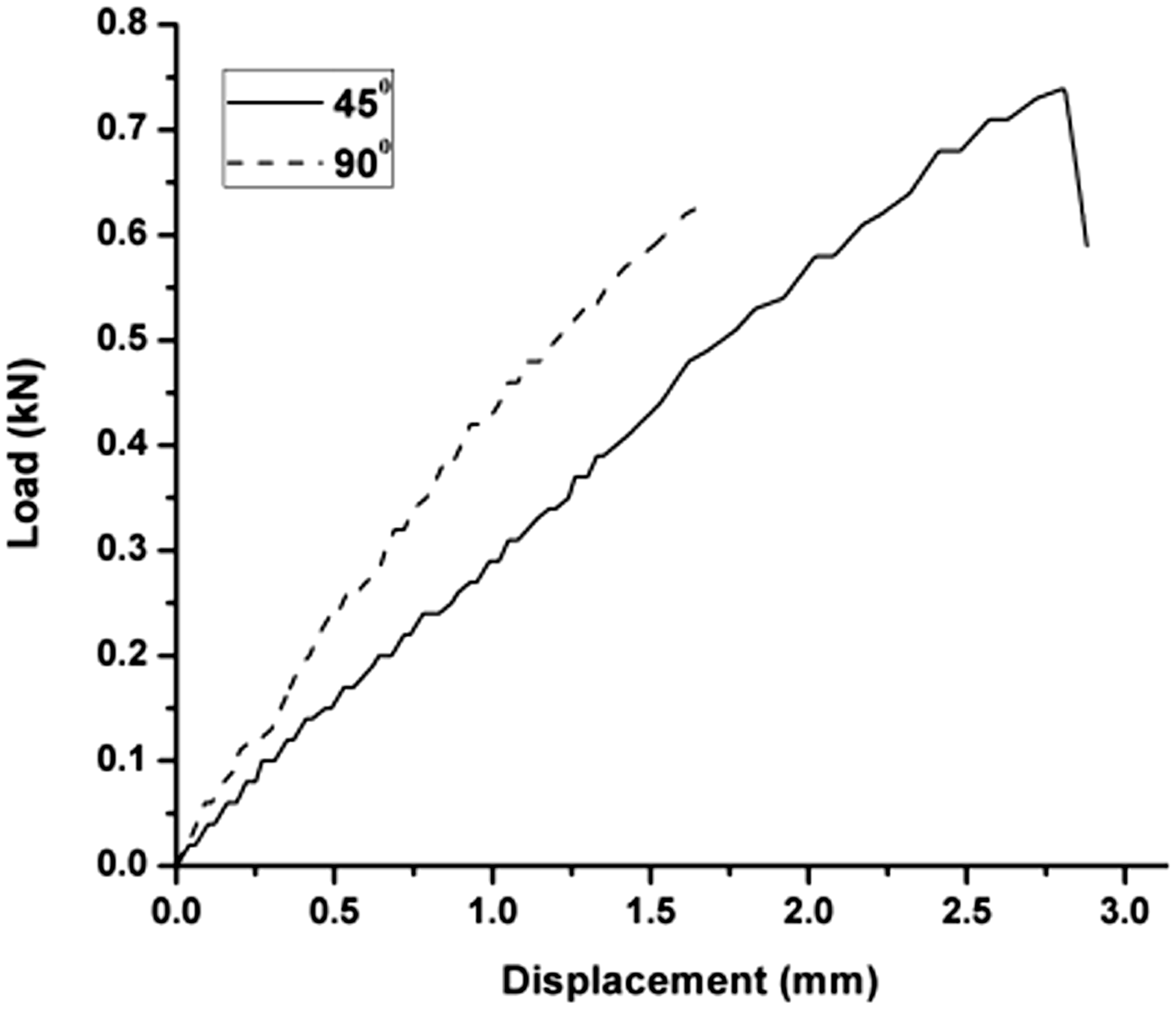
The flexural strength of WMC with 45° orientation is higher than 90° oriented composite. The flexural behavior of different oriented WMCs is depicted in Figure 6. The result indicates that the flexural strength of the 90° oriented WMC shows 3.9 mm, whereas 45° WMC shows 5.3 mm. The obtained maximum extension is due to the higher compatibility and good bonding strength between the wire mesh and epoxy resin. The effect of wire mesh at the center has reduced the circumferential stress and thereby increment of flexural strength occurs.

Flexural behavior of WMC samples.
The interlaminar test is conducted to find the bond strength between fiber, wire mesh, and resin. The interface/interphase strength depends on the adhesion between the jute fiber/wire mesh and epoxy resin. However, the reinforcement of the wire mesh significantly increases the delamination toughness of composite. The composite having 45° orientation shows the enhanced delamination toughness than the other. A typical load–displacement diagram for both 45° and 90° oriented WMC is shown in Figure 7.

Interlaminar behavior of WMC samples.
The response of differently oriented WMC shows nearly linear at the initial loading stage for both orientations. This trend is same until it reaches an apparent elastic limit and after that the curve starts a decreasing trend. The 90° oriented composite shows a significant decrease in load, just after the peak load. The 45° oriented composite achieved the highest peak load. Table 4 lists the ultimate load, maximum deflection, and ultimate stress of WM composites.
Interlaminar strength of WMC samples.

WMC: wire mesh composite.
Figure 8 shows the microstructural images of interlaminar behavior of jute fiber/stainless steel wire mesh/epoxy hybrid composites. The 45° oriented composite shows better bonding between the layers of jute fiber and steel wire mesh. The complete resistance to delamination is observed. Some transverse tensile cracks are identified only at the bottom layer of the laminate due to high tensile stress. The 90° composite shows the separation between jute fiber and stainless steel wire mesh. Some tensile cracks are also identified at the bottom layer. Figure 9 illustrates the impact strength of the jute fiber/wire mesh epoxy hybrid composites. The amount of energy absorbed is measured in Joule scale unit for each specimen. The 45° oriented hybrid composites resulted in significant increase in energy absorption than the 90° oriented mesh fiber.

Interfacial bonding between fiber and the reinforcement in the WMC samples. (a) 45° orientation and (b) 90° orientation.

Energy absorption of WMC samples.
DMA
The dynamic mechanical properties of WMC are measured using dynamic mechanical analyzer DMS6100 SII (Inkarp) at three different regions like glassy, transition, and rubber region. Initially, three samples are tested and the values are presented by the storage modulus (E′), loss modulus (E″), and damping factors (tan δ) as a function of time and frequency. The tests are conducted at three different operating frequencies (0.5, 1, and 5 Hz) and the performances are compared with two different oriented (45° and 90°) hybrid composites. The obtained results (Figures 10 to 13) show the major changes captured at the transition region compared to the glassy and rubber region.
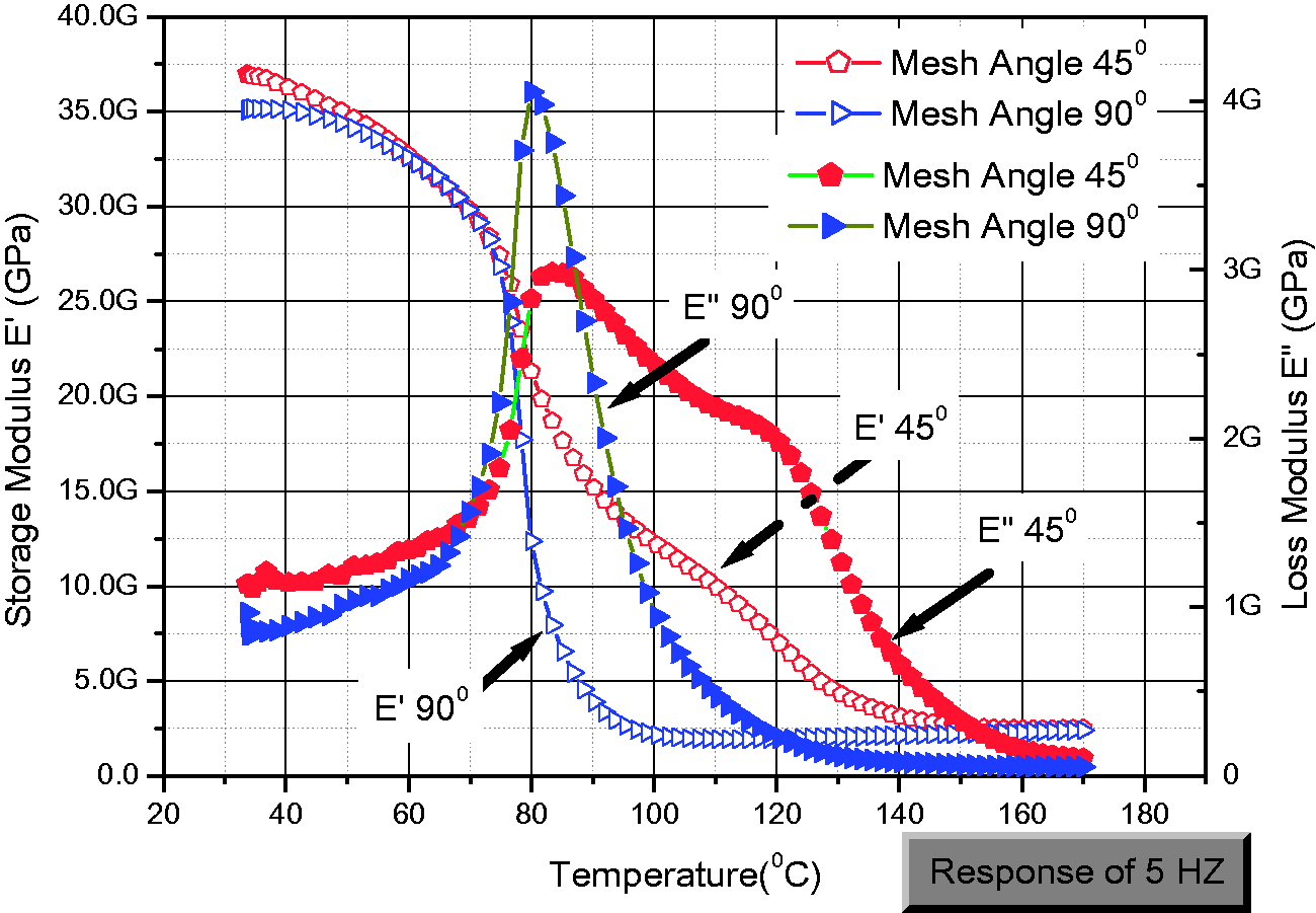
At glassy region, the 45° WMC shows higher storage modulus of 35.5 GPa at 0.5 Hz (Figure 10). The increase in heat input (2°C/min) considerably reduces its storage modulus. Due to high molecular dislocation, the storage modulus drastically reduces in the transition region compared with other regions [24]. From Figure 10, it is observed that the 45° WMC shows high storage modulus in all the three regions than the 90° WMC. The glass transition temperature is also reduced for 45° orientation than 90° (Table 5). The value of storage modulus for different frequencies (0.5, 1, 5 Hz) in these two hybrid composites has slim variations (Table 5).

Storage modulus of WMC samples at 0.5 Hz frequency.
Amplitude of storage and loss modulus at a different frequency.

The 45° WMC exhibits the loss modulus of 1.15 GPa at 0.5 Hz frequency in glassy region, whereas the higher values of loss modulus is found in 90° WMC for the same region. On the other hand, the transition region records the high loss modulus (E″) for 90° oriented WMC (Table 5). This effect is may be due to the drastic drop in the storage modulus values in transition region (Figures 10 to 13). The 45° oriented WMC has a wide curve in the transition and rubber region due to the reinforcement between the fiber, matrix, and wire mesh (Figures 10 to 12). The 45° oriented WMC shows higher loss modulus values in rubber region [38].

Storage modulus of WMC samples at 1 Hz frequency.
Storage modulus of WMC samples at 5 Hz frequency.
The damping factor (tan δ) is obtained by relating the storage modulus (E′) and loss modulus (E″) magnitudes (Figure 13). In the glassy region, only a small amount of difference is found in tan δ values, nevertheless in the transition region, the 90° WMC shows high damping factor values for all the frequencies (0.5, 1, and 5 Hz) (Figure 13). The influence of storage modulus in the transition region emphasis the damping factor in the 90° WMC specimen. In the rubber region the change in frequency shifted the damping factor amplitude in the 45° WMC specimen (Table 6). For all the frequency range, 45° WMC has minimum tan δ peak due to the orientation of wire mesh and its difference in storage modulus (E′) and loss modulus (E″) values in the transition region. Further, the polymer dilution reduces the modulus value in the rubber region due to its high temperatures [38].

Damping factor of WMC samples at a different frequency.
Peak damping factor for different WMC samples.

WMC: wire mesh composite.
Effectiveness constant
The effectiveness of wire mesh on the storage modulus of the hybrid composites can be signified by a factor of η [36]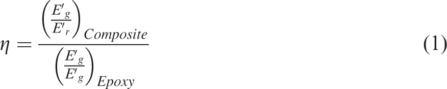
Effectiveness of the wire mesh at different angles.

SEM analysis
The SEM images of the steel WMC specimens (Figure 14(a) to (f)) reveal fiber failure during tensile and flexural testing. The orientation of the wire mesh makes highly anisotropic in all directions, i.e. in 45° orientation, the mesh wires are act as transverse to the fiber orientation at the surfaces. The zig-zag crack failure is found due to transverse orientation of the wire mesh [39], whereas the wire mesh oriented in the longitudinal direction shows cleavage mode of failure (Figure 14(d) to (f)). The interfaces, de-bonding, wire mesh, and fiber pullouts are analyzed through fracture surfaces. Figure 14(a) to (f) indicates a small amount of fiber pullout and fiber breakage is found at few regions, which necessitates a strong interface occurs between the fiber and matrix.

SEM images of 90° WMC sample (a) to (c) and 45° WMC sample (d) to (f).
Conclusion
In this work, the mechanical behavior (tensile, flexural, impact, and interlaminar) and DMA analysis of 45° and 90° oriented wire mesh hybrid composites are studied. The flexural strength has been increased to 34% in the 45° oriented wire mesh hybrid composite sample than 90° oriented sample. Moreover, 26% of deflection is noticed in 45° oriented wire mesh sample. The reinforcement of the wire mesh significantly increased the delamination toughness of the composite. The 45° oriented WMC has shown significant values increased in energy absorption than 90° oriented WMC. The 45° oriented WMC exhibits higher storage modulus (35.5 GPa) and lower loss modulus (1.15 GPa) at 0.5 Hz frequency in the glassy region. In the transition region, 90° oriented WMC results in high damping factor of 0.061 at 0.5 Hz frequency. The higher reinforcement efficiency is found for 45° oriented WMC due to lower value of effectiveness constant.
Overall, the study revealed that the 45° oriented WMC shows better mechanical and DMA properties compared to 90° oriented WMC.
Footnotes
Declaration of conflicting interests
The author(s) declared no potential conflicts of interest with respect to the research, authorship, and/or publication of this article.
Funding
The author(s) received no financial support for the research, authorship, and/or publication of this article.