
Abstract
Self-heating GNPs-based electrical networks were successfully obtained for their use in electrothermal applications. The electrical resistance of the GNPs-networks created on glass fiber fabrics was strongly dependent on fiber direction. The electrothermal response was fast and the maximum temperature was achieved in the system after ∼20 s. Increments in temperature above 80°C were obtained at the surface of the coated glass fiber fabric at relatively low intensity currents. Cyclic self-heating did not cause appreciable diminution in performance. Additionally, their potential application in evaluation of the quality of dispersion of the nanoreinforcement was demonstrated, as regions with lower contents in GNPs showed higher temperature due to weak links between GNPs located in highly conductive paths forming the electrical network.
Keywords
Introduction
Due to the low temperatures reached in high altitude locations, ice can form on wind blades, causing loss of efficiency in power generation [1]. Almost 20% of wind turbines are located at places susceptible of ice formation because these emplacements make possible to increase power generation near a 10% [2]. Although there are different methods to prevent and solve this problem [3,4], the use of electrothermal materials in blades is a potential solution for anti- and deicing [1]. For anti- and deicing systems (ADIS), the required heating is not high, needing increments of temperature in the range of 30 – 50°C, depending on the severity of climatic conditions.
But these materials are applicable not only in ADIS, but also in many other applications that require controlled self-heating of the material and temperature sensors. Conductometric gas sensors are an example. Conductometric gas sensors usually operates at temperatures between 100 and 500°C by using an external heater [5]. If the required temperature was reached by the sensor itself (self-heating), the external heater would not be necessary. In these devices, the required heating is very high (100 – 500°C), implying the need to increase the applied voltage. Additionally, self-heating materials are also potential candidates for shape memory polymers (SMP), whose shape change mechanism is usually heating-tailored [6,7]. The temperatures required are varied, from a few degrees up to one or two hundred. The use of self-heating SMP is a key question to real-life applications, especially in locations where external heating is not possible or difficult to achieve [8]. Other applications include sorbents for cleaning-up of crude-oil spills [9], where heating contributes to diminish viscosity of crude-oil; acceleration of curing of thermoset-based materials [10], where using relatively low voltages (<20 V), the time can be reduced by more than one order of magnitude; and wearable thermal textiles [11].
Nowadays, the main objective in electrothermal materials is achieving high efficiency, regarding fast electrothermal response and low operation voltage [12]. Different reinforcements have been used to achieve self-heating materials, such as carbon nanotubes [13], silver nanowires [14], carbon fibers and carbon black [15,16]. In this work, the use of graphene nanoplatelets (GNPs) is proposed to generate high efficiency self-heating lines in glass fiber fabrics.
Materials and methods
Materials
Graphene nanoplatelets type M25, provided by XGScience, with an average lateral size of 25 µm and less than 6 nm of thickness were used as nanoreinforcement. The glass fiber fabric was an E-type fabric UD 4H Satin (HexForce® 01031 1000 TF970). This fabric is unbalanced weight, with distributions of 87/13 (warp/weft), a thickness of 0.24 mm and a nominal weight of 305 g/m2. The filament diameter is 9 µm with a linear density of 136 tex.
Methods
Coating of glass fiber fabrics
Dispersion of the GNPs was carried out in ethanol, using a concentration of 5 wt%, via probe sonication in a UPS400S, from Hielscher. The process was performed with an amplitude of 50% and a cycle of 0.5 for 45 minutes. The GNPs content and dispersion method has been determined based in previous experimental studies to achieve the percolation threshold.
Lines with a width of 2 mm and lengths of 25, 50, 100, 200, and 400 mm were painted by screen printing on the glass fiber fabric right after the dispersion process was complete in order to avoid agglomeration of the GNPs. Two different painting directions were used: along 0 and 90° directions, named 0°-lines and 90°-lines, respectively. These two painting directions were used because the unbalanced weight of the fabric could potentially impact self-heating properties, as more efficient electrical network could be created along warp direction. Once the lines were painted, ethanol was evaporated in an oven at 60°C for 24 h. Two GNP-based layers were deposited to achieve the final coating.
Microstructural, electrical and self-heating characterization
Scanning electron microscopy (SEM), particularly a Hitachi 3400, was used to characterize the morphology of GNP-based coating.
The characteristic I-V (intensity-voltage) curves of the GNP-based lines was measured using a source meter unit instrument, Keithley 2410. Copper wires were used as electrodes, which were attached with silver paint to minimize the electrical contact resistance at the two ends of each line, i.e. distanced 25, 50, 100, 200, and 400 mm, as schematized in Figure 1. The electrical conductivity was calculated from the I-V curves following the Ohm’s law at voltages from 0 up to 25 V, in order to avoid the effect of heating.

Scheme of GNP-based lines and electrical contact position.
Self-heating was analyzed by applying a constant voltage of 25, 50 and 75 V using a source meter unit instrument, Keithley 2410. The electrical current intensity and the temperature were simultaneously recorded with a Keithley 2410 and an infrared thermal camera Flir E50, respectively, in order to analyze the heating profiles. The heating curve is generated from an average of three tests by analyzing the temperature reached in the whole line area. Cyclic heating (10 cycles) at the three studied different voltages (25, 50 and 75 V) was also performed to study the efficiency of the heating lines over usage. Each voltage was applied for 1 minute to ensure the maximum temperature is reached.
Results and discussion
Morphology and electrical behavior of self-heating lines
The morphology of the electrical network created by the GNPs on the surface of the glass fiber fabrics can strongly condition the electrical conductivity and, consequently, self-heating of the GNP-based lines. Figure 2 shows SEM micrographs of the GNP-based lines along two different directions of the glass fiber fabric: 0°-lines (Figure 2(a)) and 90°-lines (Figure 2(b)). When coating is deposited along 0°, a homogeneous distribution of the nanoparticles is observed. In contrast, lines placed along 90° showed regions with low GNPs contents and others where GNPs are accumulated. This fact is attributed to the presence of a higher number of fibers perpendicular to the painting direction, which acts as blockers for the GNPs. Although this effect was also observed along 0°-lines, it was not significant.

SEM micrographs showing GNPs disposition for layers in directions (a) 0° and (b) 90° of the glass fiber fabric; and details of GNPs (c) bridging and (d) adaptation to the fiber surfaces.
It is important to note that GNPs form bridges between individual glass fibers, as it is shown in Figure 2(c), which makes the electrical network more efficient. Additionally, due to the 2 D character of the GNPs and their low thickness, they adapt to the surface of glass fibers (Figure 2(d)), also contributing to ensure continuity along the coating [17].
As the electrical behavior of the GNP-based lines is dependent on the morphology of the electrical network, Figure 3 shows the characteristic I-V curves of both 0°-lines and 90°-lines for lengths of 25, 50, 100, 200, and 400 mm; and the calculated electrical conductivity for each direction. As expected, the electrical resistance of the lines, which is the inverse of the slope of the I-V curve and can be obtained from the electrical conductivity values, is higher for longer lines. Although this is an obvious fact, this is going to condition the maximum distance between contacts to achieve efficient self-heating coatings, which in this case is settled preliminary at 200 mm.

Characteristic I-V curves as function of the electrodes distance for layers in directions (a) 0° and (b) 90° of the glass fiber fabric, and (c) electrical conductivity. [Note: at 50 V, some of the samples reach the maximum compliance of the equipment and intensity above that voltage cannot be measured].
One important issue to take into account is that the electrical conductivity of 0°-lines is higher than that of 90°-lines (Figure 3(c)). This difference is attributed to the morphology of the coatings. As it has been mentioned above, in 90°-lines, regions with low concentrations of GNPs were found, which resulted in less connectivity trough the electrical network. Additionally, the 87% of the fibers is placed along the 0° direction, therefore, as GNPs adapt to the fiber’s surfaces, the electrical network is more efficient along this direction, despite of fiber bridging. These two contributions make that lines painted along 0° result in a more efficient electrical network and, consequently, in lines with higher electrical conductivity.
Other interesting result that can be observed is the loss of I-V linear proportionality at relatively high electrical current transported, which is the reason of calculating the electrical conductivity from values obtained up to 25 V. This could be an inconvenience for electrothermal applications if the voltage used is above the change of tendency and does not remain constant during the operation. For the highest electrical conductor fabrics, the electrical current increases exponentially at relative high voltages. This phenomenon has been previously observed and it is related with the increment of temperature associated to self-heating. For these electrical networks, an increase of temperature induces a reduction of their electrical resistance.
Because of the higher electrical conductivity of 0°-lines at low voltages, they were selected to perform the analysis of self-heating properties.
Self-heating performance
Figure 4 shows representative heating curves at different voltages for 0°-lines with lengths of 25 (Figure 4(a)), 50 (Figure 4(b)), 100 (Figure 4(c)) and 200 mm (Figure 4(d)). A constant heating rate was observed in all the cases and the maximum temperature was reached in less than 20 s. This rapid response, i.e. low time, is one order of magnitude lower that that reported by P. Tang et al. [18], who published a value of 400 s for nanocomposites reinforced with carbon nanotubes (CNTs) and carbon fibers (CF); and H. Lu et al. [19], 136 s for nanocomposites reinforced with CNTs.
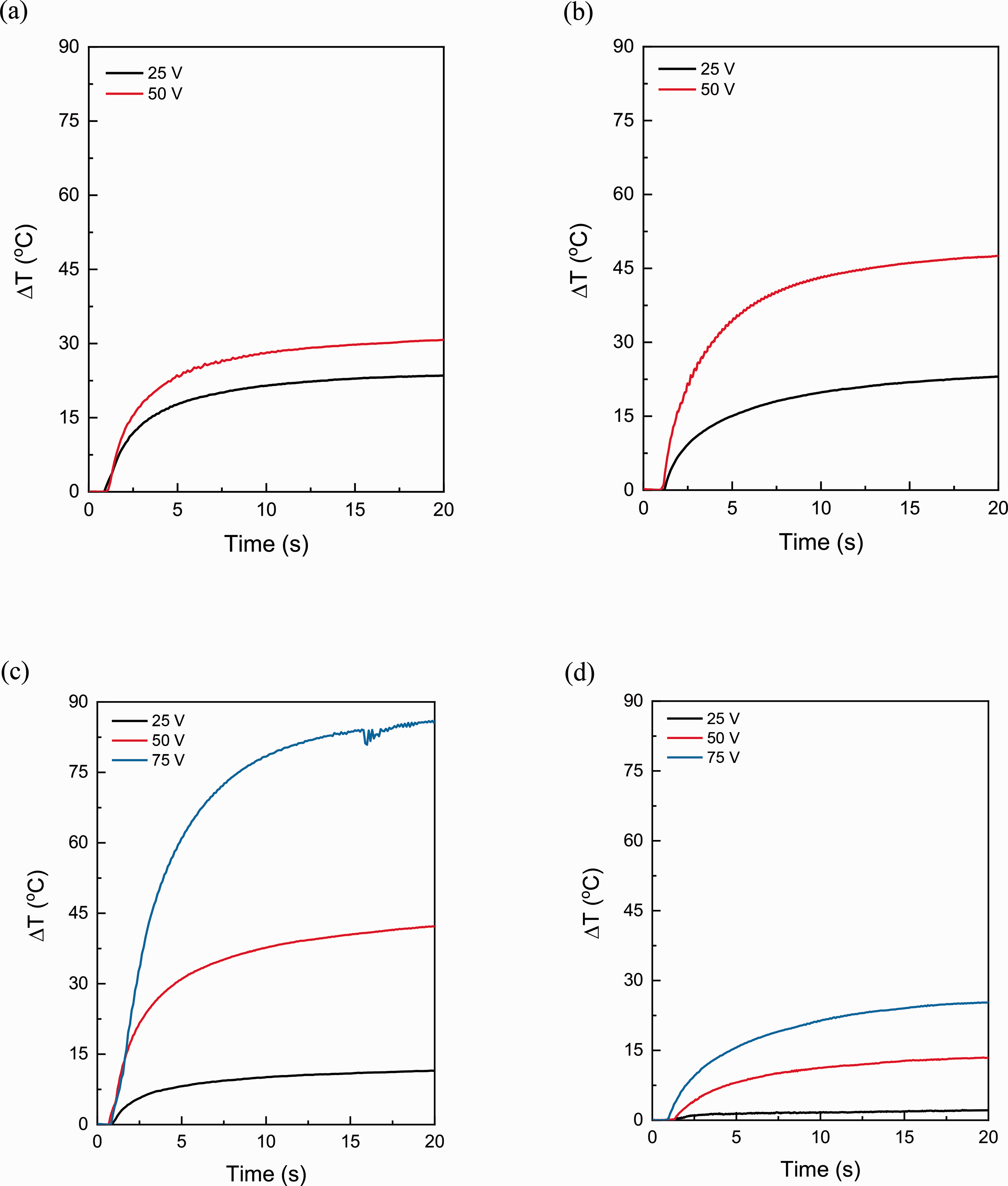
Self-heating behavior at different voltages (25, 50 and 75 V) for layers in direction 0°: (a) 25 mm, (b) 50 mm, (c) 100 mm and (d) 200 mm of the glass fiber fabric [for lengths of 25 and 50 mm; voltage of 75 could not be applied because of the maximum compliance of the equipment].
Lines 25 mm long showed heating with a maximum increase in temperature between 20-30°C for applied voltages of 25 and 50 V. By increasing the length of the line up to 50 mm (Figure 4(b)), the electrical resistance augments, and so does the increment of the maximum temperature that the system can reach, which enhances the heating capability up to a 60.9% for 50 V. Higher voltages could not be studied in lines with lengths of 25 and 50 mm because of the compliance limit of the equipment. In the case of lines 100 mm long (Figure 4(c)), a similar effect can be observed, the increment of the maximum temperature increases near 200 and 80% related to the ones with a length of 25 and 50 mm, respectively. But it is not effective below 75 V because of the low electrical current circulating at 25 and 50 V, which is too low to achieve an effective heating. For lines 200 mm long (Figure 4(d)), the heating capability considerably diminishes. The obtained increments in temperature are slightly higher than the ones reported by A. Dorigato et al. [20], but the differences can be attributed to the lateral dimensions of the GNPs used. The GNPs used in this work have higher lateral dimensions, 25 µm in contrast to 5 µm, so it is easier to create an efficient electrical network.
Although self-heating capability of CNTs-based nanocomposites is higher, achieving temperatures above 60°C at 2.8 V in a length of 19.5 mm [21], the thermal conductivity of GNPs-based nanocomposites is higher [22,23], contributing to a uniform heating.
In order to make these facts evident, Figure 5 shows the current intensity circulating and the power required when saturation of heating curves occurs, as well as the increase of temperature obtained in each case as a function of the applied voltage. For low voltages, i.e. lower than 25 V, the heating is more effective in shorter lines, which is associated to the circulation of a current of higher intensity. In contrast, at high voltages, higher increments of temperature are obtained in longer lines up to 100 mm at a low power, below 0.3 W. Above 100 mm, the electrical current circulating along the line is too low, because of the high electrical resistance, to achieve an efficient heating.
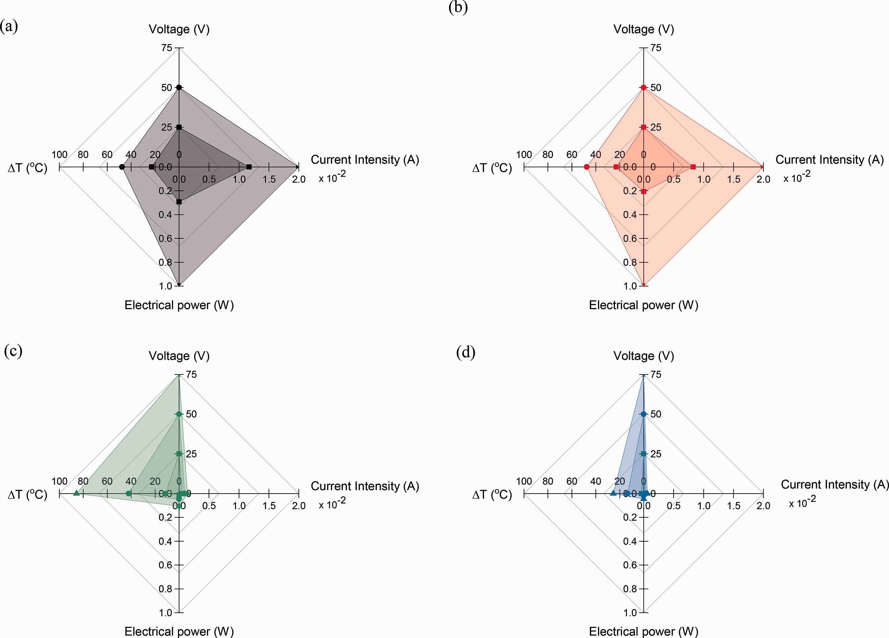
Self-heating parameters depending on the applied voltage for lines with length: (a) 25 mm, (b) 50 mm, (c) 100 mm and (d) 200 mm.
M. Loeblein et al. [24] have reported a BNC-infused 3 D-foam with self-heating capability that reaches temperatures of 200°C with an applied voltage close to 20 V and an electrical current of 50 mA. Although this temperature is higher than the obtained in this work, the power needed is one order of magnitude higher. J. Seyyed et al. [25] also improved self-heating in multiscale composite materials (carbon fiber reinforced polymeric composites), by the addition of thermally exfoliated graphene oxide, reaching a maximum temperature near 40°C under a constant current of 1 A. Note that carbon fiber is also a conducting material and contributes to heating.
As the line achieving higher maximum temperature was the one 100 mm long, this length was selected to perform cyclic heating. Figure 6 shows the increment in the maximum temperature per cycle reached during the test for applied voltages of 25, 50 and 75 V. As it can be seen, up to 10 cycles, the increase in the maximum temperature remains constant and, thus, there is no detriment of self-heating in the GNP-based lines.

Evolution of the temperature increment with cyclic electrical fields of 25, 50 and 75 V with electrodes at a distance of 100 mm.
To deeply study if there is any loss of efficiency in heating, the initiation time (time to reach the maximum temperature), heating rate, relaxation time (time to reach the initial temperature) and cooling rate per each cycle are analyzed. Figure 7 shows the obtained results for these parameters. For the initiation, relaxation time and the cooling rate, no differences were observed after 10 cycles. In contrast, a slight difference in the heating rate was detected. The heating rate slightly diminishes at the second cycle and remains constant up to the tenth cycle. This phenomenon is more pronounced for higher voltages and can be attributed to the fact that the formation of electrically conductive pathways in the network is enhanced. The first voltage application requires the formation of electrically conductive pathways by tunneling effect, in addition to direct contact, which implies a higher heating rate.

Evolution of self-heating parameters with cyclic electrical fields (25, 50 and 75 V): (a) initiation time, (b) heating rate, (c) relaxation time and (d) cooling rate with electrodes at a distance of 100 mm.
Inhomogeneities detection through self-heating
Although the main application of these systems is as self-heating material for anti- and deicing, another potential application could be the detection of inhomogeneities in GNP-reinforced materials, i.e. nanocomposite and multiscale composite materials.
To analyze detection of inhomogeneities as potential application, heating was performed in 0°-lines and 90°-lines to detect the presence of non-homogeneous distribution of GNPs. Representative images of performed tests are shown in Figure 8.

Inhomogeneities detection through self-heating (orientation/length/applied voltage): (a) 0°/50 mm/200 V, (b) 0°/100 mm/100 V, (c) 90°/50 mm/200 V, (d) 90°/100 mm/100 V, (e) 90°/200 mm/150 V and (f) 90°/200 mm/200 V.
For lines parallels to the dominant fiber direction (0°-lines) with lengths of 50 and 100 mm, a homogeneous heating was observed, as it is shown in Figure 8(a) and (b), respectively. In contrast, in lines perpendicular to the dominant fiber direction (90°-lines) with same lengths and applied voltages, a non-homogeneous heating can be observed, as it can be seen in Figure 8(c) and (d), respectively, where some regions reach temperatures above 40°C and other remains at room temperature. These results are in accordance with the microstructural analysis carried out in section 3.1, 0°-lines show homogeneous GNPs content through all the surface while 90°-lines present regions with low GNPs contents and others with considerable higher contents. The heating is, therefore, more significant in regions poor in GNPs since the electrical current circulating through the GNPs is relatively higher than in regions with GNPs agglomerations, what results in higher power dissipation and, as a consequence, in higher temperatures [26]. This phenomenon has been also explained by K. Maize et. al [14], who corroborated by high magnification infrared thermography that the maximum heating arises in weak links located in highly conductive paths forming the electrical network. But heating only happens along GNPs that are connected within a conductive path [27].
This phenomenon is more appreciable in lines with a length of 200 mm (Figure 8(e) and (f)), where heating is mostly located at isolated areas showing significant differences of GNPs concentration along the 90°-lines.
Apart from supporting the better distribution of GNPs in 0°-lines already discussed, these results evidence the potential applicability of these materials as self-analyzers of nanoreinforcement distribution in GNPs reinforced nanocomposites.
Conclusions
Self-heating GNPs-based lines was successfully obtained for their use in electrothermal applications. The system showed a fast electrothermal response and significant heating at relatively low intensity currents and power. The increase in temperature was homogeneous in the surface in lines along dominant direction of fiber (0°C) while it was not in the perpendicular axis (90°C), showing that a good dispersion of the GNPs is crucial to achieve high efficiency and homogeneous electrothermal systems.
Increments in temperature above 80°C were obtained at the surface of the coated glass fiber fabric for voltages of 75 V and cyclic self-heating did not cause appreciable diminution in performance. Additionally, their potential application for the evaluation of the quality of dispersion was demonstrated, as regions with lower contents in GNPs showed higher temperature due to weak links located in highly conductive paths forming the electrical network.
Footnotes
Acknowledgements
The authors would like to thank the Comunidad de Madrid Government (Project ADITIMAT-CM, S2018/NMT-4411).
Declaration of conflicting interests
The author(s) declared no potential conflicts of interest with respect to the research, authorship, and/or publication of this article.
Funding
The author(s) disclosed receipt of the following financial support for the research, authorship, and/or publication of this article: This article was funded by the Project ADITIMAT-CM, S2018/NMT-4411, Comunidad de Madrid Government.