
Abstract
The main motive for this research is the desire for the improvement of the automotive seat occupant’s comfort by designing a heating mat prototype made with distance knitting technology with heating elements. In this study, the following design steps were undertaken: preparation of the trajectories of heating cables, calculating the resistance needed to obtain the estimated power of the whole mat, testing of available electroconductive yarns to assign the most suitable yarn to a specific design, preparation and testing of five heating mat prototypes with three various trajectories of the heating element. All samples were evaluated with the same criteria in order to find the most promising design. After all experiments, a prototype with stainless-steel Bekaert® VN 12.2 coated yarn as a heating element, showed the best performance, especially in combination with distance knitted fabric thanks to its internal construction. This work demonstrates that a three-dimensional distance knitted fabric with a heating element introduced into its structure will ensure the physiological sitting comfort. After further subsequent studies, the proposed method can be adapted for industrialisation by using warp knitting machines, thus improving the quality and durability of the heating mat.
Introduction
Many passenger cars, as well as other types of vehicles, are equipped with heating systems useful in countries with low temperatures throughout the year, or seasonally. Heating elements not only provide users with thermal comfort in such weather conditions but also protect drivers from prolonged exposure to low temperatures, which can be dangerous to their health. Another function of the heating elements in cars is to improve visibility by preventing the windows and mirrors from fogging up or frosting. The construction of vehicles is characterised by a wide range of styles and trends [1], and manufacturers always strive to implement the latest technologies and design guided by functional and aesthetic criteria which provide passengers with comfort, ergonomics, and safety [2,3]. Passengers’ comfort is becoming increasingly important in the car industry, thus not only manufacturers of car seats but also manufacturers of all necessary components face new challenges such as raising the level of user’s safety, new production requirements, and work on user’s sitting position. A big part of the user’s comfort is his thermal comfort described as ‘that condition of mind which expresses satisfaction with the thermal environment’ [4] in Standards No. ISO 7730:2005 and ASHRAE 55-74. Therefore, an analysis of heat flow and temperature distribution must be carried out when designing new seats [5].
Since the big expansion in the electronics industry, it was only a matter of time for textiles to become something more than just a covering fabric. From the 20th through the 21st century, we can observe rapid development of textiles which increasingly perform more advanced functions [6,7] and are no longer limited to being only a covering material. As a result of the intensive development of technology, the range of various innovative textile solutions is growing every year. Those solutions are generally called smart textiles, and their application areas are limitless [8,9]. Their application of upmost importance includes the control of vital functions used in the field of medicine, and moreover, the application in protective clothing to monitor the activity of firefighters, soldiers, or other employees of state services. Some smart textiles include LED wires into their fabric structures to make modern clothing more visible and to increase safety in conditions of limited visibility. On a side note, developments taking place in military and medicine fields can be very easily adapted into sportswear products to monitor body activity in real-time or enhance the user’s comfort in any conditions [10]. Implementation of miniaturised electronics into regular clothing enhances their properties and provides them with new functions they did not have before. A phenomenon that is now emerging is the textile system (textile + non-textile = textile system), which among other functions such as electroconductive (EC), optical conductive, fluorescent, and releasing substances, currently it can also be thermo-radiative, i.e. it has the possibility of giving out heat [11]. The current study concerns the innovative application of heating technologies in smart textiles. Therefore, only these technologies will be discussed below.
A big part of heating textiles is represented by heated clothing [12]. In Lotens’ expanded table of human’s approximate thermal strain criteria, we observe that only inner body temperature (measured in the rectal area) needs to reach 37°C for a state of comfort, while fingers and toes need 27–34°C [13]. The scientist concludes that our skin needs 33°C to attain a pleasant feeling [13]. Garments, which can protect our body from cold, not so long ago were based only on multilayer structures with a non-absorbent inner layer [14]. Owing to new possibilities of combining heating technologies with flexible materials like textiles, heated clothes are to be one of the most widely used products that would integrate textile materials and electronics in the near future. Lately, producers and researchers have seen the potential in this kind of products, and each year, more studies get conducted with an aim at finding the most efficient heating system that can be incorporated into a flexible material such as textile or clothing [15].
Several heating fabric technologies were taken into consideration in order to select the most suitable technology that could be applied in car seat heating mats. A comparison of their main advantages and limitations has been made, thus leading to the selection of heating material for further development. The most important thing for heating and cooling in car seats is the top layers. That was a focus of all inventors who worked on such systems. They started from the simplest arrangements of flexible tubes and pipes through which the air was supplied [16]. Nowadays, this technology, called forced-air warming, is mostly used in heated mattresses and blankets in the medical field mainly to prevent the formation of pressure ulcers when the patient is exposed to hypothermia [17], e.g. during transportation or hospitalisation. Another medical application of forced-air warming is to ensure an adequate and constant temperature in infants with low birth-weight [18]. However, this system is sometimes insufficient when it comes to being effective, and therefore, a better alternative system was developed, called circulating-water garment [19], where warm water circulates in a special garment through flexible tubes.
Nevertheless, this system works well when the patient lies still, whereas in a driving situation or continuous sitting down and getting up from the car, seat tubes would be exposed to permanent deformation, perforation, or other mechanical damage. Moreover, they would make the seat uncomfortable [16]. Therefore, in this paper, the focus is on conductive yarns since they are a more promising product when it comes to the flexibility in the heating fabrics [20]. All conductive materials have a resistivity below 103 Ω cm. EC raw materials with the best conduction parameters are silver, platinum, gold, copper, stainless steel, and carbon.
The heating mats for the car seats produced nowadays consist of a single underlay and a heating element attached to their bases in various ways usually well protected by the producers. Currently, heating mats designed for car seats are produced using methods that ensure high performance at low cost. For this reason, the quality of the manufactured product is a secondary value, especially in lower-class cars. Therefore, bases are usually thin and non-woven or sponges, which are later modified by applying a heating element. Such an element is usually insulated copper wire because it ensures obtaining sufficient temperature values at reasonable costs. The wire could be attached to the base in one of the following methods: by attaching the heating wire to a continuous non-woven base using automatic industrial embroidery machines, then the final material is cut into a suitable shape for a heating mat; by an automated sequence of machines, where the glue is sprayed onto a non-woven base of a predetermined shape, and then the heating wire is put in a suitable shape, and during the last stage the top layer of the non-woven fabric is being stacked to give stability to the product and to hide the glue; by a base made of a thin sponge covered with glue, then the heating element is applied and last comes the thin non-woven layer, which covers the remaining adhesive on the mat.
However, the methods mentioned above come with some technological limitations. The most common problems mentioned by producers are as follows: multistage process of making a single mat; unsatisfactory endurance of clamping the heating element to the mat base; low durability of such mats for mechanical forces, such as abrasion or loads resulting from the weight of the sitting person and one’s mobility.
A key advantage in the presence of a heating mat built into the car seat is the maintenance of a constant temperature regardless of the weather conditions. The perceived temperature a person feels from the heating mat is radiant, and it is different from convection (heat carried from the blowing of warm air, as it happens when using only conventional heating blowers). Humans perceive the radiation heating as more pleasant and therefore, more comfortable [21,22]. In addition, the heat from the mat moves directly into the user’s body (Figure 1(a)), so it takes shorter to feel warm and comfortable. The typical car seat heating mat consists of an underlay and a heating element that is attached to its base in various ways. Heating element trajectory designs used in originally built-in automotive seat heating systems are highly protected by producers; however, on the market, many separate heating mats can be incorporated into any car seat structure. Those products usually have very similar or almost identical patterns (Figure 1(a) and (b)). Currently, heating mats designed for car seats are produced using methods that ensure relatively high performance at low cost. For this reason, the quality of the manufactured product is a secondary value, especially in low-budget cars.

In relation to such specific objectives of the literature review, the following research hypothesis is assumed: a 3D distance knitted fabric with heating elements introduced into its structure will ensure the physiological sitting comfort. The main research goal of the current study is to improve the sitting comfort by designing a heating mat prototype made with distance knitting technology with heating elements.
Furthermore, the study is to show the innovative possibilities in knitting technologies, the potential and wide range of products that could be obtained as a result of those methods whose capabilities are still in the development phase. Finally, the presented prototypes in this study aim at developing an optimal heating mat design that could be adapted for industrialisation after further subsequent studies. Moreover, the paper suggests that using warp knitting machines would improve the quality and durability of the heating mat.
Experiment methods
The experimental stage of the study was conducted in the Centre for Textile Science and Engineering at Ghent University for determining which of the chosen heating mat designs show the best and most promising performance.
The first attempts to design a distance fabric with an electrically conductive heating element which could be manufactured in one production process on a warp knitting machine were undertaken after thorough literature review [26–30].
The most important parameters needed for subsequent calculations such as the full size of the heating mat, the number of heating elements and their length and exact trajectory were precisely defined in a design process. The size of the destined heating mat was 50 cm per 30 cm, and it was determined based on market research and the most common sizes of products of similar type. In this case, the manoeuvre could only be done by various patterns of placing the heating element and by different resistance of the wire itself. In the current study, the following three design steps were undertaken: (1) preparation of the trajectories of heating cables, (2) calculating the resistance needed to obtain the estimated power of the whole mat, and (3) preparation and testing of samples. Detailed methods of the steps are outlined below.
Three trajectory patterns were prepared. Due to limitations in performance of spacer fabric knitting machines, and after further extended practical and theoretical knowledge, the final designs were characterised with the following features [31,32]: placement of a heating element was unidirectional, the straight trajectory of the heating element line was avoided not to limit the stretchability of the base material, the trajectory of a heating element within one design was kept in even distance in order to provide the most uniform heating, the smallest distance between heating yarns was 1 cm to avoid hotspots.
A yarn that forms the heating pattern in spacer knitted fabric should have strong resistance in order to provide enough power. Meaning that once established, the resistance for a specific pattern should stay the same during the use of the final product. The chances of interruption or damage to the circuit should also be minimised [33].
When an EC yarn is introduced into a textile structure, e.g. into weft knitted structure, it creates a loop whose bottom half arcs would touch the yarn’s top arc [34]. As a consequence, short-circuit points would begin to arise (Figure 2), and between two surfaces of contacting yarns, a contact resistance would arise whose value depended on the contact force between those two areas having contact and on the cross-section surface [34,35]. The process of analysis of a loop contact mechanism was very complicated and not entirely explained. Therefore to avoid problems caused by the presence of contact points in heating textile element developed in this research, it is better to design a structure where they do not occur or use a coated yarn, so there is just one way for current to flow.

Short-circuit points within the knitted loop structure [34].
At present, the power sources used in cars usually provide a voltage of 12 V and in big trucks −24 V. Therefore, for further calculations to estimate necessary parameters for the heating mat designs, the voltage of 12 V was determined as the maximum, even though we could supply low voltage devices with higher voltages. The target value of power adopted in the project (40 W) was based on a literature review [36–39] and market research. Therefore, the necessary resistance per heating mat was 3.6 Ω (equation (1)). In order to provide such values, a heating mat design had to include both the trajectory of the heating element and estimated ideal linear resistance (equation (1))

Three final trajectory designs presented in Figure 3, each with different length of a single cable and with a different number of those cables on the width of the heating mat, were selected for experimental testing.
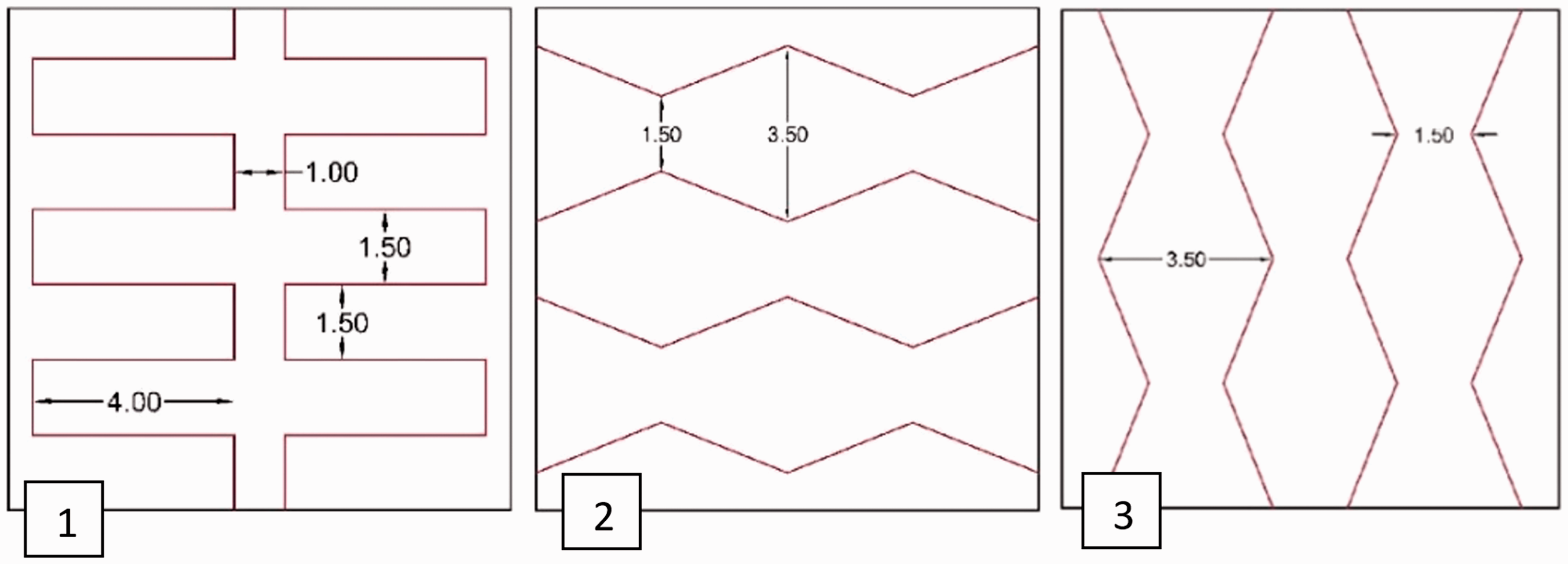
(a) Mirrored ladder vertically – longwise the mat, (b) mirrored zigzag horizontally – crosswise the mat, and (c) mirrored zigzag vertically – longwise the mat.
It was assumed that the behaviour of a full-size mat would remain the same no matter its dimensions. Hence, at the final stage, five types of small-sized samples and two knitting designs were prepared for evaluation of their heating performance. The estimated power value of the whole heating mat was 40 W, and since one entire mat could be divided into 15 small samples with dimensions of 10 × 10 cm (Figure 4), the relevant value per sample was 2.67 W regardless of whether the circuit connection was longwise or crosswise the mat.
Using a stitching or embroidery machine deforms the structure of the distance knitwear, whereas stitching the heating element precisely on one of the material surfaces by hand could resemble warp knitted structure. Hence, all samples of EC yarns were stitched carefully by hand on a selected type of spacer fabric (more details in the ‘Materials’ section). Consequently, further scientific work will aim at adapting the final prototype for industrialisation with a warp knitting machine.

Dimensions of an entire mat and a single sample in red. Lines divide the entire mat into 15 samples of equal dimensions of 10 by 10 cm.
Temperature readings of the connected samples to a power supply and electric circuit were done with appropriate apparatus such as a thermographic camera. For more precise measurements of selected areas, the data from the IR camera were processed with a thermal analysis computer software, viz. FLIR ResearchIR. The selected area for analysis covered the same central part of each sample. As for internal temperature readings and circuit resistance, a thermocouple and an ohmmeter were used, respectively.
Due to time constraints, the experimental stage was divided into several sub-stages, and with each consecutive stage, fewer samples were tested. The decision on which samples would pass on to the next evaluation stage was made based on conclusions and observations after the preliminary test, and that process is described in the ‘Results and discussion’ section.
Materials
As it was already mentioned before, the quality of the top layers is crucial in any product which supports the human body. Hence for car seats as well, everything to provide the best airflow within its upholstered back and the bottom cushion is of utmost importance. The growing interest in spacer knitted fabrics is the result of appreciating their excellent characteristics [40]. They have excellent mechanical and strength parameters at low specific gravity. The structure of the middle layer in the spacer fabrics is spatial, and therefore, it comprises a number of air spaces. This property gives products of this material very high thermal insulation, much better compared to flat textiles. However, despite numerous free spaces, the distance knitted fabric has very good dimensional stability.
Other great features of spatial knitwear are their high air permeability and the ability to transport moisture. These advantages play a significant role in preventing the development of bacterial flora, and at the same time, they increase the user comfort and satisfaction from the product. This, so-called breathability of spacer materials, maintains body heat in balance no matter the change in the external conditions and body activity [41]. Given the above, a heating mat developed within this work was based on this structure. All samples were prepared with spacer knitted underlay that is visible in Figure 5. The outside surfaces of distance material were made of polyester yarn. Polyester is a very common fibre used in the automotive industry [1]. Its main advantages are high resistance to abrasion, good UV resistance, and that it is relatively inexpensive. The inner layer of distance material was formed using synthetic monofilament yarn, which is typical for this type of textile.

Heating element samples (left: Bekinox® VN 14.3 EC yarn (ladder trajectory), middle: carbon fibre yarn (zigzag trajectory), right: placement of the thermocouple for central temperature measurements inside the samples).
In the current study, the authors considered the cost and resistance factors of the EC elements. All conductive materials were with a resistivity below 103 Ω cm. EC raw materials with the best conduction parameters in descending order were silver, platinum, gold, copper, stainless steel, and carbon. Due to the rarity and high costs, the first three metals were treated with reserve. Hence, only one silver-coated yarn was used and its performance evaluated. Copper, on the other hand, was a very good conductor, meaning that its volumetric resistivity was very low (1.72 × 10⁻⁶ Ω cm). When it came to good conductors, such as copper, according to the resistance definition, a very long or thin wire would be needed in order to reach 3.6 Ω on a heating mat. Thin wire, even though made of relatively flexible metal, becomes susceptible to damage and that might cause circuit interruption. Also, a single-threaded wire, when inserted into the flexible structure of a knitted fabric, ensures hardness and easy breakability (see composition in Table 1). This continuous wire inserted into the flexible structure of a knitted fabric prevented damage and circuit interruption.
A third prototype sample was made using carbon fibre as a heating element which is also an example of EC yarn. The fibres in such yarn are usually made out of carbon nanotubes [42,43].
All accessible information of the exact yarns used within this study is presented below.
Yarns used in the first design:
Yarns used in the second design: A conductive thread called HC40 produced by Madeira company [44]. It was made of 100% polyamide and was fully silver-plated. Its linear density was 290 ± 6 dtex. Carbon fibre-based yarn Toho Tenax Co. type Tenax®-E HTA40/E13/15Z [45]. Its linear density was 200 tex. Continuous stainless-steel filament yarn type Bekinox® VN 14.1 without insulation coating [46]. Its linear density was 110 tex. Only one type of yarn was used for this prototype; no other available EC yarn showed the right resistance to obtain the estimated power value within this design.
Yarn used in the third design:
Results and discussion
After stitching appropriate EC yarn onto a particular sample, yarns were connected in parallel, and the resistance over each sample was measured with ohmmeter in order to verify if the measured value meets the one calculated with equation (1). Those values are presented in table 3 as a summary, along with other relevant results and discussed later in this chapter. In order to make all results comparable, temperature measurements were conducted in a climate-controlled room with constant conditions, i.e. temperature = 23 ± 3°C, and humidity = 25 ± 2%.
Available EC yarns were tested to find those most appropriate for each design [48]. The basic four-point method was used in order to learn the resistance of the EC material. This method, widely used for such purposes, was recommended by the specialist in the field of electronic textiles and textiles for heating purposes – Ereprof. Dr Ir Gilbert De Mey [49,50]. The first step was preliminary resistance tests, which aimed at estimating the differences between available conductive yarns and finding yarns in the range of resistance, which at 12 V would give 40 W of power in the whole heating mat. Therefore, they were measured with bigger relative error, in order to find a larger range of suitable EC yarns. In the second part, only the most suitable yarns underwent the same method of testing to determine their linear resistance with such accuracy that the relative error would not exceed 2–3%, i.e. a relative error that is statistically significant.
As we can observe in Table 2, none of the available EC yarns gave exactly the estimated 40 W of power per heating mat. Yarns matched to designs were characterised with linear resistance giving output values, as close as possible, to the estimated ones. Getting a supply of a conductive yarn with a specific linear resistance is easier than trying to achieve much closer values to the estimated ones. A manufacturer like Bekaert company offers a wide range of standard or custom-made conductors with an electrical conductivity that ranged from 0.1 to 70 Ω/m or more [51]. Yarns used as prototypes gave about 40 W of power. The purpose of this study was to evaluate which type of yarn would give the best heating effect with the calculated power value. Furthermore, the study is to determine which trajectory would show the best uniformity and what would the dynamics of heating and cooling overtime be.
Composition (wt%) of the Bekinox® VN yarns, AISI 316 L[27].

Estimated power values of selected heating mat designs.

There were five samples of each design. Within every experiment, each sample was tested four times, and the differences were not statistically significant. In each stage of testing, a different aspect was considered in terms of thermal performance. In the first stage, five designs prepared in the form of samples were compared based on uniformity of their heating (Figure 6) and their maximum and minimum temperature within a sample (Figure 7). Therefore, samples were tested separately to thoroughly investigate the propagation of temperature around the heating element (i.e. EC yarn). Temperature values visible in each picture refer only to the area marked with a rectangle. However, those images come straight from the IR camera. For a more accurate comparison of the samples, the temperature readings, which served to prepare all charts, were made using a FLIR ResearchIR computer program, described earlier in the ‘Experiment methods’ section. The program allowed selecting the exact area from where the data should be read. The chosen area was the same in each sample, and it included a central with dimensions of 5 cm × 5 cm. Furthermore, the program’s functions made possible the limitation of the influence of air exchange at the edges of the samples on the measurement results.

Photos from thermographic camera taken after 1 min of heating each sample: (a) Bekinox® VN 14.1, (b) Bekinox® VN 14.3, (c) carbon fibre, (d) Madeira HC40, and after 40 min of heating each sample: (e) Bekinox® VN 14.1, (f) Bekinox® VN 14.3, (g) carbon fibre, (h) Madeira HC40. Temperature values visible in each picture refer only to the area marked with a rectangle.

Temperature stabilisation during 40 min of heating – examples. (a) Carbon fibre as heating element – without upholstery and (b) Bekinox VN 12.2 as heating element – without upholstery.
In Figure 6, we can observe that zigzag trajectories do not show as even uniformity of heating as it was presupposed from the conducted theoretical and market research. A significant number of heating mats with this type of zigzag pattern being produced nowadays led to the unambiguous conclusion that this solution provides very good performance. However, laboratory tests show that this kind of pattern did not heat the air evenly in the middle layer of the sample; thus, cold spots were visible throughout the process. Even after 40 min of heating, cold spots did not disappear although all the yarns used in zigzag designs reached much higher maximum temperature, which means that heating for more than 40 min does not enlarge the heated area.
The best performing samples were chosen for further analysis. After that, in the second stage of the experiment, both heating and cooling behaviour were examined. Another objective in the second stage of testing was the temperature measurement during the 40 min of heating. Exemplary results are presented below in the form of graphs for easy comparison. Measured values showed some similarities between the samples. In most samples, the maximum temperature got stable within a few minutes and then oscillated around the reached value. Some EC yarns took longer to reach maximum temperature, e.g. carbon fibre took around 15 min (Figure 7), and other yarns took less than 10 min. The yarn that heated the fastest was Bekinox® VN 12.2 (Figure 7). Hence a conclusion could be drawn that coated yarns stabilise their temperature faster than uncoated ones. Difference between maximum and minimum temperature in tests of the sample with Bekinox® VN 12.2 without upholstery persisted between 20 and 26° (Figure 7); in fact, the minimum temperature of this sample during the entire experiment was among the three highest minimum temperatures. Meaning that it is located among three prototypes where the heat propagation is the most regular, which makes these products more effective and energy efficient. Automotive seats have a large contact area with their occupants; therefore, it is very important to heat this surface evenly. Uniform heating is a key to better comfort.
Another observation during the test was the breaking of carbon fibre yarn without coating when the sample was being attached to wires connecting it to the power source. In that situation, the resistance tended to rise even up to 10 Ω and with 4 V (as this yarn was with horizontal trajectory – across the mat) would result in just 1.6 W per sample, and thus 24 W per whole heating mat (accordingly to equation (1)) would be less than any tested design. The most probable explanation was the occurrence of fibre breakage and loosening of the structure, which resulted from the clamping of yarns into the electric circuit. However, when the difficulties related to fixing the sample to the circuit were overcome, heating performance and temperatures obtained in experiments gave very promising results. Carbon fibre yarn showed very good heating properties when compared with other tested heating elements. As presented in Figure 7, the maximum temperature of both presented yarns oscillated close to similar values. Although Bekinox VN 12.2 yarn achieved stable maximum temperature faster than the other yarns, it could be noticed that it was not maintaining it perfectly, while carbon fibre was problematic at the beginning of the experiment. However, after achieving stability, the carbon fibre maintained it well at an even level without significant deviations. It even had a tendency for small growth. If obtaining this type of carbon fibre yarn with a protective coating is possible, it should be tested and evaluated again. The suitable way of fixing this breakable carbon fibre yarn into circuit should allow utilising its heating advantages.
In Table 3, we can observe that the power measured within a particular sample was never precisely the same as the calculated value for the selected design. However, two types of yarn gave higher power in the experiment than in the calculations, viz. Bekinox®.
Power values juxtaposed with the maximum temperature obtained.

Green oval marks the power values in a way they are compared in the discussion below. Arrows show the direction of change of the measured values to the calculated ones.
VN 14.3 and Bekinox® VN 12.2. Both yarns were used in the same design (Table 2) and both were with the same trajectory shape. Nevertheless, the difference was not very big, whereas when it came to the zigzag trajectory, the values measured on samples dropped significantly in contrast with the predicted (calculated) values. We could deduce that this phenomenon was due to the number of wires connected together and further to the power source. In so-called ladder trajectory (Figure 3(a)), there were two EC threads connected together, and in zigzag trajectory (Figure 3(b) and (c)) there were four. Thus, a conclusion could be made that the amount of EC yarns in one connection affects performance. However, in order to verify the exact relation between those factors, more studies should be executed.
Some other observations have been made during this experiment. First and most important is that whenever the power increases, the obtained temperature rises. Another is that just one sample (with Madeira HC40 as heating yarn) provided more power than required per sample (2.67 W). However, this yarn showed to be the most problematic due to its finesses, and it was prone to burns and breakage.
There were two pairs of yarn which gave similar output power, but very different maximum temperature, viz. Bekinox® VN 14.1. and Bekinox® VN 14.3., and Bekinox® VN 12.2. and carbon fibre. In both cases, the two compared samples had different trajectories (like the pair in Figure 5). The samples with ladder trajectory gave lower temperature readings with 3–5° than the samples with a zigzag trajectory (see Table 3). However, looking carefully at Figure 6, uniformity of heating plays a much more important role in this measurement. In ladder trajectories, a current passed evenly through all cables, whereas in zigzag trajectories such evenness of connection was more difficult to obtain, causing higher temperatures in one of the branches.
Each sample examined in the first stage of testing showed the advantages and disadvantages of particular designs and yarns used within them. However, a selection had to be made. After that stage, two samples with the highest maximum temperature obtained in the experiment and two samples with the best uniformity of heating were selected for further testing. Among the two samples with highest maximum temperature was the Madeira HC40 without coating as a heating element. Indeed, it was a problematic yarn because its silver coating was easy to wear down or destroy, and it led to uneven heat propagation, and it even burnt during the process. We can observe the phenomenon in Figure 6(d) and (h), where the yarns have visibly different temperatures (indicated in different colours). Madeira HC40 yarn is very sensitive to mechanical damage, which is not good for future car seat usage. If obtaining this type of silver-coated yarn with a protective coating is possible, it should be tested and evaluated again, because its heating performance is very promising. Likewise, after the first phase of experiments, the carbon fibre rejection of the Madeira HC40 yarn would be too precipitant.
Samples where Madeira HC40 was used as a heating element were characterised by reaching much higher maximum temperatures compared with other samples after the same time of performance (Figure 6). Within this experiment, we were researching the power values of particular yarns and the temperatures they provided. Main objects of interest were the achieved temperature values, uniformity of heating, and deviations of actual values from the theoretical values. Issues of incorporating heating elements into the circuit were secondary at this stage of the research. A sample that was rejected after this selection was the one with Bekinox® VN 14.1 EC yarn because it showed the biggest discrepancies in values obtained from those calculated before experimental testing (Table 3). The reason behind the discrepancy was the difference in obtained power that was significantly smaller than the calculated value. Among zigzag designs, this one had the lowest maximum temperature (Figure 6(a) and (e)) and second-lowest among all examples. Sample with Bekinox® VN 14.3 EC yarn might, at first glance, look like the better choice for rejection due to its lowest maximum temperature. However, this temperature itself is not low. Moreover, the power obtained was higher than that resulting from the calculations (Table 3), and the heating element trajectory resulted in much less visible cold spots (Figure 6(b) and (f)).
In the second stage of experiments, heating mat samples were covered with upholstery fabric in order to create car seat-like conditions and compare them with temperatures obtainable in real car seats. In this experiment, both, heating (40 min) and cooling (15 min) behaviours were examined.
Figure 8(a) and (b) has hysteresis shapes, whose course is more or less smooth. Figure 8(b) representing an inside temperature of samples has the most regular shape due to the least external influence. All samples reached over 40°C inside the spacer fabric. Those temperatures in samples with carbon fibre and Bekinox® VN 12.2 yarn remained very similar almost throughout the whole time. Figure 8(a), where the surface temperature is presented, shows that the sample with Bekinox® VN 12.2 yarn started cooling down sharply a few minutes later than other samples, although the power was turned off at the same time (after 40 min) for each sample. Moreover, a maximum temperature on the surface of this sample did not drop as much as in samples with carbon fibre or Madeira HC40 after turning off the power supply. The coating prevents the Bekinox® VN 12.2 yarn from direct contact with the air, making the convection of the heat difficult. The heat released by the metal yarn in this sample must move through the coating before it can dissipate, whereas other yarns being in contact with air cooled down faster due to easier convection. Therefore, the surface temperature of the Bekinox® VN 12.2 yarn remained warm longer and cooled down slower than in other samples.
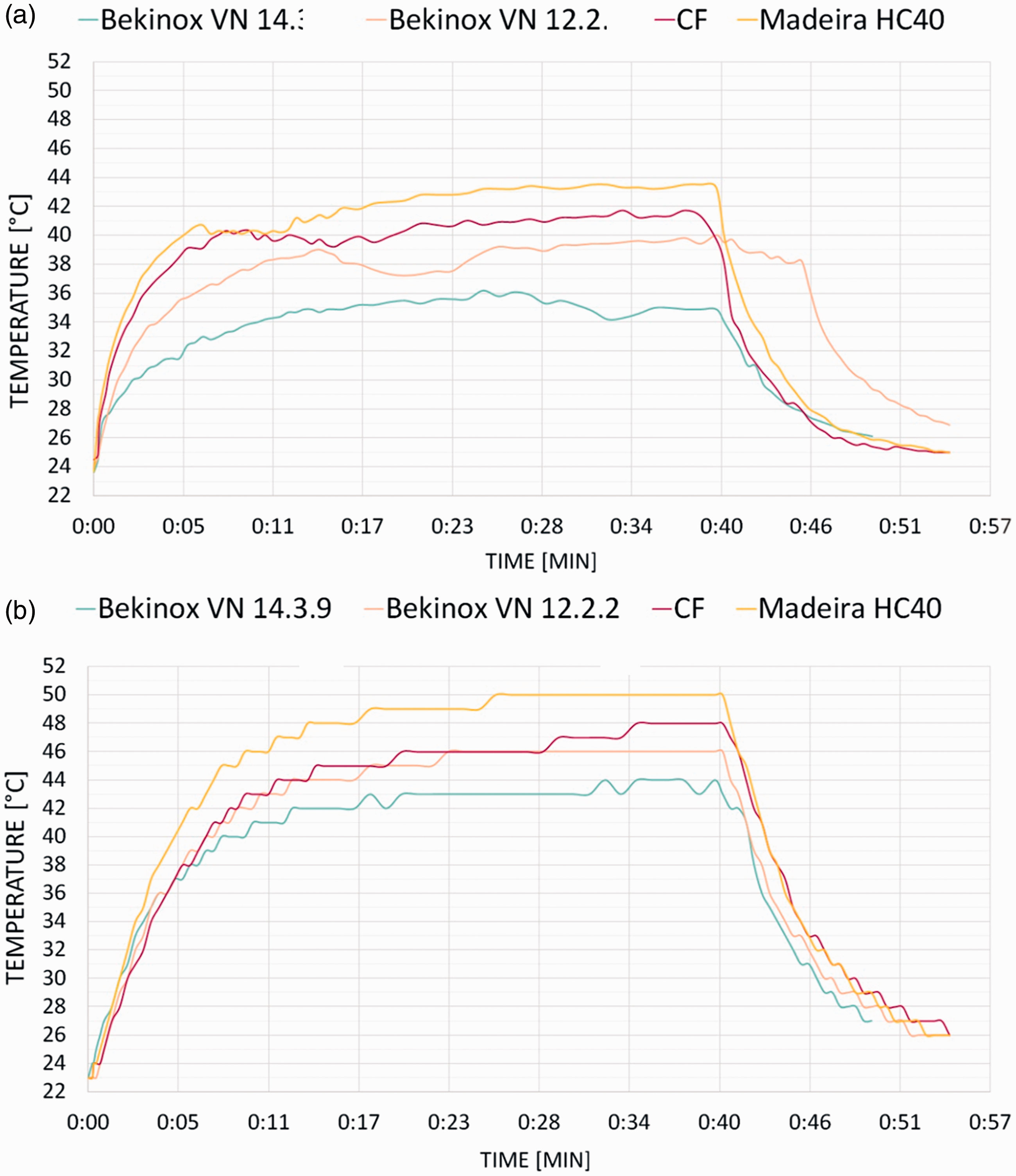
(a) Maximum temperature on surface in heating and cooling test with upholstery and (b) the temperature inside a sample in heating and cooling test with upholstery.
Figure 9 shows the differences between coated and uncoated yarns used in the experiment. It shows the time the samples took to reach 28°C. In the heating and cooling cycle, this temperature was reached twice – first in the heating part and later in the cooling part. We can observe that speed of a heating up to 28°C was almost equal for each sample. However, the speed of reaching the predetermined temperature in the cooling part was again visibly uneven. The sample with coated Bekinox® VN 12.2 yarn dropped to 28°C a few minutes later than other yarns.

Time of reaching 28°C in minimum temperature on the upholstery surface during heating and cooling cycle.
Temperature values juxtaposed in Table 4 confirm that automotive upholstery acts as an insulator creating a barrier that keeps the heat flow inside. We can easily observe that the temperature on the surface of tested samples is visibly smaller than the maximum temperature of the heating element itself. The biggest temperature drop, in this case, is observed in the design with EC yarn Madeira HC40. The car seat cannot be built without upholstery; however, this material can be adjusted so that more heat could pass towards the passenger’s body. A positive aspect of upholstery behaving as an insulator is that the warmth created by EC yarn heats the air inside the spacer layer. We can see this temperature gain in Table 4 as the temperature difference between parameters T3 and T4. An increase in the temperature inside the sample helps to improve the uniformity of heat distribution on the surface of upholstery fabric. Therefore, we observe differences between parameters T2 and T3. Three yarns (Bekinox® VN 12.2, Carbon Fibre, and Madeira HC40) gave almost the same temperature difference between the considered parameters. Nevertheless, it is the sample with Bekinox® VN 12.2, which provided the smallest loss of temperature of the heating element when passing to the upholstery surface.
Presentation of temperature (°C) gain and loss for particular designs.

Academic research and experiments confirm that spacer knitted fabric will ensure better physiological sitting comfort, whereas the implementation of an EC wire into spacer knitted fabric structure can create an innovative heating element infused with many possibilities. Promising heating performance of a final structure developed within this work proves that such elements can compete with car seat heating mats that are currently used in the industry. Someday even replacing them, since, besides good heating action, they provide very good ventilation and hygiene. Prototype 1, the sample with Bekinox® 12.2 coated yarn as a heating element, showed the best performance undisputedly after all experiments. This design was chosen because of its complexity and the optimum of most of the parameters examined. It showed very good uniformity of heating in both experiments with or without upholstery. Considering the power at which maximum temperature is reached, the effect is very satisfying and allows to heat the surface of the upholstery fabric perceivably. It is also important that the inclusion of this yarn (Bekinox® 12.2 coated yarn) into the circuit does not significantly change the output power value compared with the same parameter resulting from the calculation. Although it did not show the perfectly stable maximum temperature during the heating phase, this yarn keeps its maximum temperature few minutes longer after turning off the power supply due to its coating. The coating has another advantage; it makes the heating element much safer when it comes to using products that are in direct contact with the human body. Therefore, a prototype with a coated yarn can be adapted for industrialisation much faster and easier.
The ProCad program is a handy tool to present the 3D knitwear structure possible to perform on particular warp knitting machine. It facilitates and significantly speeds up the process of customisation to large-scale manufacturing [26]. Nevertheless, the process of optimising the knit structure with a heating element developed within this study is time-consuming and is left as a subject of further research.
Figures 10 and 11 show one of the first simulations. All of the most important parameters of the machine available in the laboratory of Knitted Textiles Department of the Lodz University of Technology were considered. The designs take into consideration the machine pitch, which is E18, the right number of needle bar guides – six, and the course density that can be obtained on this machine – eight courses per 1 cm. This parameter and needle gauge determined the lap distances in the design of the heating element’s trajectory using the modelling chain links. From the calculations, it was found that there are approximately 72 needles per 10 cm. Therefore, patterns of the proposed spacer knitted fabrics are characterised with large repeats. The trajectory of the heating element arrangement refers to the prototypes presented in this study. However, in this particular simulation, some modifications had to be made in order to obtain an openwork pattern in the top layer (Figure 10(b)) and channels in inner layer perpendicular to the planes of external layers (Figure 11). Therefore, there were only two needle guide bars left, one was used to form the back layer of the knit structure, and the other one inserted into the EC yarn. Thus, the heating element could not form the mirrored ladder pattern, but only one half of it, as presented in Figure 10(a). The use of openwork pattern and inner channels is aimed at increasing the breathability of the fabric and improvement of ventilation, which according to researchers from National Renewable Energy Laboratory can result in A/C fuel use reduction [52]. This structure will also ensure better transport of warmth from heating element towards the inside of the mat in order to heat the whole fabric and the air contained in the middle layer.

Computer simulation of a spacer knitted fabric structure with a heating element. Simulation of the front layer weave structure. After simulating relaxation, the openwork is visible.

Knit of the layer forming a distance. Designed to be made by two guide bars (4 and 5 – yellow and aquamarine) with part threading. It aims at creating channels perpendicular to the planes of external layers.
After introducing appropriate records for chain links for individual guide bars in the ProCad program, it turned out that some of the projects are too complex for the program to execute an efficient simulation. Hence the conclusion that a computer program is only a tool that helps a person in his actions, and we should not blindly rely on it. Simulations must be patiently repeated, especially the relaxation process. These limitations make the design stage a time-consuming process.
Conclusions
Five heating mat prototypes were experimentally tested within this study. All samples were evaluated accordingly with the same criteria used to evaluate the most promising design that improves the thermal comfort of the automotive seat occupant. This work demonstrates that a 3D distance knitted fabric with a heating element introduced into its structure will ensure the physiological sitting comfort. Knitting technologies have many more innovative possibilities, and a wide range of products could be obtained thanks to those methods whose capabilities are still in the development phase.
The research allowed to draw the following conclusions: The EC yarn itself should be resistant to mechanical use and be completely safe because of human contact. Therefore, a good solution is to use coated yarns in any product that is to heat the human body. Prototypes with a more curved trajectory of the heating element showed very good uniformity of heating in all experiments. Zigzag patterns do not show as even uniformity of heating as it was assumed from theoretical and market research, this kind of pattern did not heat the air evenly in the middle layer of the sample; thus, cold spots were visible during the whole time. Upholstery added on top of a heating fabric sample acts as insulation and heat produced by heating wire is spreading within a distance layer of spacer fabric and warms up the air contained in this space. Moreover, the inner temperature increases significantly, and the overall temperature of the heating mat surface is evener. Optimisation of prototypes for one manufacturing process on warp knitting machines will improve their quality and durability.
Amount of EC yarns in one connection into the electric circuit affects performance: The more yarns connected in parallel and later into the electric circuit, the smaller the output power in relation to the calculated value is. Continuous filament yarns behave better in electrical connections. They also do not break so easily; therefore, they are more appropriate for flexible structures. We can conclude that coated yarns (Bekinox® VN 12.2) stabilise their temperature faster than uncoated ones. The coating prevents direct contact with the air, making the convection of the heat difficult. Heat released by metal yarn in this sample must move through the coating before it can dissipate, whereas other yarns in contact with the air cool down faster due to easier convection.
In order to verify the exact relation between those factors, more studies should be executed.
Supplemental Material
JIT883061 Supplemental Material - Supplemental material for Textile elements for car seat to improve user’s driving comfort
Supplemental material, JIT883061 Supplemental Material for Textile elements for car seat to improve user’s driving comfort by Michalina Warska, Marcin Barburski and Lieva van Langenhove in Journal of Industrial Textiles
Footnotes
Acknowledgements
The research has been carried out during the master’s degree of Michalina Warska at the Lodz University of Technology and her partial education abroad at Ghent University thanks to the Erasmus+ Programme. Special thanks go to Dr Benny Malengier for sharing his invaluable knowledge with us and always supporting Ms Warska. We also thank Ereprof. Dr Ir Gilbert De Mey and Dr Inż. Katarzyna Pieklak for their patience and all their help during our research. Last but not least, authors would like to thank Yuliyan Zhelyazkov for his voluntary work in language polishing and proofreading the manuscript.
Declaration of conflicting interests
The author(s) declared no potential conflicts of interest with respect to the research, authorship, and/or publication of this article.
Funding
The author(s) received no financial support for the research, authorship, and/or publication of this article.
Note
References
Supplementary Material
Please find the following supplemental material available below.
For Open Access articles published under a Creative Commons License, all supplemental material carries the same license as the article it is associated with.
For non-Open Access articles published, all supplemental material carries a non-exclusive license, and permission requests for re-use of supplemental material or any part of supplemental material shall be sent directly to the copyright owner as specified in the copyright notice associated with the article.