
Abstract
In this study, a high-tenacity polyester was used to produce biaxial weft knitted fabric in three different loop densities. All of the composite samples were manufactured using the vacuum injection process. Epoxy resin was used as the matrix in the composite samples. Tensile tests in the course and wale directions were carried out on all samples. The results showed that the tensile strength and the elastic modulus of the composites were improved by increasing the loop density. On the other hand, multi-scale finite element modeling was employed to predict the elastic constants and the tensile strength of the composites. In this method, unit-cells of biaxial weft knitted fabrics with a script were modeled by ABAQUS finite element software in the meso scale. Periodic boundary conditions were applied to the unit-cells. Stiffness matrices of composites were calculated by a python code. In the macro model, a shell geometry was created and the elastic constants calculated from the meso scale were assigned to the macro model. The tensile strength of composites in the course and wale directions was predicted by the Tsai-Wu failure criterion equations. The numerical results had a good agreement with the experimental ones. According to the numerical results, the difference in the loop densities as the inputs data could be used and elastic constants and strength of composites in the course and wale directions could be obtained. So, this model is a useful method to predict the tensile behavior of biaxial weft knitted composites with different geometries.
Introduction
Recently, the use of textile composites has been extended in many industries such as civil engineering, automotive, aerospace, and construction [1–3]. Biaxial fabrics are a textile structure reinforced by two series of yarns through the length and width of the fabric. The presence of straight yarns plays a reinforcing role in the fabric structure [4]. Knitted structures due to excellent formability could be produced in simple and complex shapes [5,6]. However, from another point of view, studies have shown that composites made from knitted fabrics represent lower mechanical properties as compared with other reinforced textile composites [7–10]. The mechanical properties of the knitted fabrics strongly depend on the loop curved architecture of the yarns. The maximum strength of the knitted preforms is generally influenced by the fiber strength, modulus, and the type of yarn, knitting pattern, stitch density, the number of knitted fabric plies, the amount of pre-tension applied to the fed yarns, the number of reinforcing in-laid yarns and the knitting process parameters. So, the mechanical properties of the composite mostly depend on the fabric properties [11]. Limitation in selecting the yarn because of the curving structure of loops is one of the weaknesses in the knitting process (such as carbon yarn) [12]. According to the previous studies, using biaxial knitted fabrics is a solution to improve the mechanical properties of knitted composites. In biaxial knitted fabric, yarns are inserted to knitted fabric thorough warp (wale-wise) and weft (course-wise) directions as a reinforcement part [13]. Due to the straight yarns in the biaxial weft knitted fabrics, the mechanical properties of such fabrics are better than those of the weft knitted fabric. Therefore, using this fabric as a reinforcement part in some composite structures whose impact resistance is of importance such as the bulletproof performance in helmets, could be suitable. As soft composites, they could be employed in such applications in which the tensile and tearing properties are one of the main concerns especially in roofing membranes, air ship, inflatable boats, and rescue tents.
Many studies have been already conducted to investigate the mechanical properties of the biaxial weft-knitted fabrics for reinforcing thermoplastic and thermoset composites [14–17]. The results have shown that biaxial knitted composites could have more resistance against the tear and tensile load. On the other hand, the tensile tests have shown that the first damage occurs as microdebonding between the loop cross-over points in the knitted fabric structure. In addition, according to a study conducted by Qi, Liu, and Li [18], the bending a properties of three-layer biaxial weft knitted (TBWK) composite with different fiber volume fraction were investigated. The results showed that the bending modulus and the bending strength of TBWK reinforced composite materials had a great correlation with the fiber volume fraction. Within a certain range, the bending modulus and the bending strength of the TBWK reinforced composite materials were increased with enhancing the fiber volume fraction, however, when the fiber volume fraction reached a certain value, the bending strength and bending modulus did not increase.
On the other hand, predicting the mechanical behavior of textile reinforced composites is one important issue in the mechanics of composites. The complex shape of knitted fabrics leads to the difficulty in predicting the mechanical behavior of knitted textile composites. Thus, using a numerical model to predict the mechanical behavior of knitted fabrics under different load conditions is considered by researchers to achieve a better performance structure [19]. Various studies have been focused on modeling and simulating the mechanical performance of textile reinforced composites [20–23]. Multi-scale finite element modeling is one of the methods used to model and predicts the mechanical behavior of textile composites by some researchers [24,25]. In this method, a unit cell of a model can be analyzed and the obtained properties are assigned to the macro model for different load conditions. Recently, some researchers have employed equations developed by Vassiliadis [19] to create a geometry of the unit-cell of a single jersey weft knitted fabric for mechanical and fluid [26] analysis. Shekarchizadeh et al. [27] also used finite element modeling in the meso scale to predict the mechanical behavior of a plain weft knitted composite. They used the Vassiliadis model [19] to model the geometry of the fabric loop. FE model outputs including stiffness constants had a good agreement with the experimental results. Hamedi et al. [28] also simulated the bending behavior of a 3D weft knitted fabric composite reinforced with the single jersey knitted fabric. They created a unit-cell geometry of the weft knitted fabric by using Vassiliadis equations and applied the periodic boundary conditions to the unit cell to calculate the mechanical constants of the composite. Weeger et al. [29] also applied multi-scale modeling in the yarn and fabric level to simulate the nonlinear mechanical behavior of a single jersey plain fabric. For modeling, the geometry of the knitted loop Vassiliadis model was used. They modeled the knitted loop by 3D beam formulation and predicted the nonlinear orthotropic mechanical behavior of the fabric. In another paper, multi-scale modeling was used to model the tensile and shear behavior of the plain knitted weft fabric by Dinh et al. [30]. Vassiliadis model was considered for modeling the knitted loop geometry. Demircan et al. [31] also, used finite element modeling to study the tensile properties of the biaxial weft knitted composite. They used a simple model based on the 3D beam element to simulate the unit cell of the model. In addition, Pham et al. [32] used meso scale finite element modeling to simulate the biaxial weft knitted fabric for the forming process. The knitting yarn system in the biaxial reinforced weft-knitted fabric was a single jersey structure. They used equations proposed by Choi and Lo [33] to model the loop geometry of the knitted structure. Hessami et al. [34] also compared the mechanical properties of the biaxial and rib 1 × 1 weft knitted composites under tensile and bending load. They also used multi-scale modeling to predict the mechanical behavior of the composite. As can be seen, most studies have been focused on the mechanical behavior of biaxial warp knitted composites or single jersey fabrics and there are limited few works on the meso-macro mechanical behavior of double jersey and biaxial weft-knitted composites. Therefore, in the present study, the mechanical behavior of a biaxial weft knitted composite with three different loop densities and under the tensile load was investigated by both experimental and multi-scale finite element (FE) modeling.
Experimental procedure
Structural properties of the knitted fabrics.

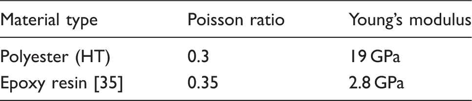
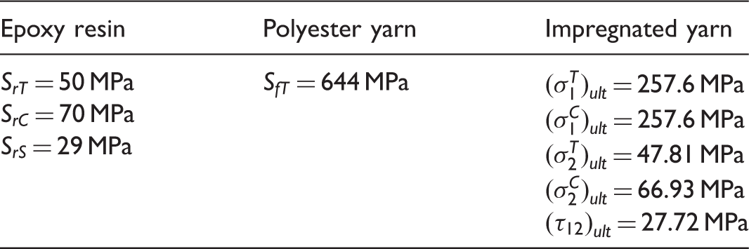
Mechanical properties of the materials.
To produce the biaxial weft-knitted fabric, the rib 1 × 1 structure was chosen as the base of the fabric and the straight yarns were inserted into the fabric as the weft and warp. The rib 1 × 1 knit pattern was chosen to produce simple weft-knitted fabrics.
All composite samples had been manufactured using the vacuum injection process (VIP), as shown in Figure 1. The epoxy resin was mixed thoroughly with its corresponded hardener with the weight fraction ratio of 100:30. Then, prior to be used in the vacuum bag molding process, the deaeration process was performed by placing the prepared mixture in a vacuum oven under a pressure of 65 bar and, at the temperature of 30 oC, for 15min. The molded samples were kept at room temperature for 24 h to be cured. To improve their mechanical properties, the samples were then post-cured during further three different heating processes in an oven in three stages: for 2 h at 45 oC, 2 h at 60 oC, and 8 h at 80 oC. Figure 1 shows the final bagging and vacuum applied.
Vacuum injection process.
Tensile test
Tensile tests were carried out on the fabricated composite samples, according to ASTM D3039 instructions, in the wale and course directions, by the Zwick tensile tester machine. Five samples of each composite type were tested and the average results were reported. The dimensions of the samples for the tensile test were 1.5 cm × 25 cm. The speed of the test was chosen to be 2.5 mm/min. Figure 2 shows the tensile test conducted on the composite sample.
Tensile test on the composite sample.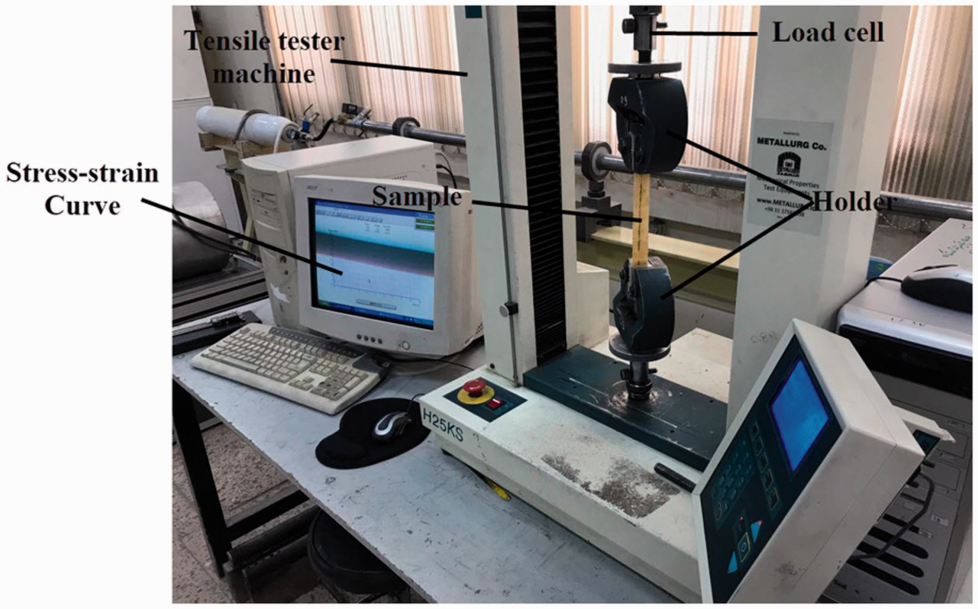
Multi-scale finite element modeling
The implementation of finite element modeling required the geometry of the unit-cell to be created. In this regard, a proper geometrical model for designing the loop geometry based on the rib 1 × 1 pattern had to be selected. Figure 3 shows the biaxial weft knitted structure and the unit-cell of the fabric.
(a) Biaxial weft knitted fabric and (b) unit-cell.
In this research, the geometrical model developed by Vassiliadis [19] was used to model the loop geometry in the Abaqus software. Thus, due to the presence of symmetry in a single loop, equations were only used to simulate a quarter of the loop.
As illustrated in Figure 3 the geometry of the rib 1 × 1 was divided into two segments. The first segment consisted of face and reverse loops that can be modeled by the equations proposed by Vassiliadis [19]. Another segment is the linking portion between face and reverse loops that could be created by the Abghary et al.'s [36] model.
For modeling the geometry of a unit-cell of fabrics, a python code based on the mentioned geometry was written. Some of the knitted fabrics' structural parameters including wale and course distance and yarn diameter were used as the inputs in the python code to design a three dimensional fabric unit-cell in the Abaqus software. The unit-cells geometry of all samples can be seen in Figure 4.
Biaxial weft knitted fabric unit-cell: (a) K1, (b) K2, (c) K3.
Elastic constants of the yarn impregnated with resin.

To implement the transversely isotropic properties of the yarn impregnated with resin, material orientation in the Abaqus software was used. The direction 1 is along the yarn axis, while the direction 2 is the direction normal to the yarn axis and the direction 3 is defined so that it can comply with the other directions to create a right-handed, orthogonal coordinate system. The material orientation of the fabric yarns is shown in Figure 5.
Material direction in the fabric yarn: (a) direction 1 is defined along the yarn axis; (b) direction 2 is defined perpendicular to the yarn axis; (c) direction 3 can form a right-handed coordinate system.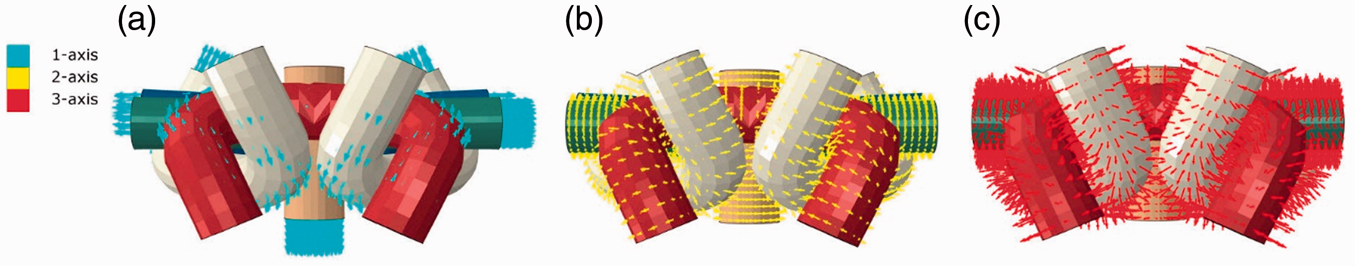
The knitted fabrics were embedded in the epoxy resin. The composite unit cell included the matrix and the yarns as shown in Figure 6.
The reinforcing yarns embedded in the matrix.
The strength of the textile reinforced composite is an important issue considered in this study. Therefore, the failure criterion developed by Tsai-Wu [38] was used to predict the strength of the biaxial weft knitted composites. According to the Chamis [39] equations the tensile and compressive strength in the first and second directions and shear strength can be calculated as follows


In equations (1) to (7), 
If the value of equation (8) is equal to 1, the failure occurs in the composite. The values of the coefficients in equation (8) can be calculated as follows
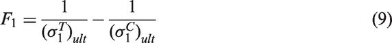


Parameter values for the Tsai-Wu failure criterion.
The above constitutive equations were implemented in the Abaqus finite element software by writing a user material subroutine UMAT.
To determine the elastic constants of the composite, periodic boundary conditions were applied to the unit-cell. The macroscopic strain increment was applied to the unit-cells by decomposing the displacement increment on the boundary into the macroscopic averaged displacement field and a period part repeated from one unit-cell to another one, such as
Periodic boundary conditions: (a) tensile load and (b) shear load.


C3D8R element type in the ABAQUS/Standard element library, which is an 8-node linear, was applied for meshing the model and a total number of 15726 elements were used for meshing of the K1 sample. In this study, yarns and matrix meshed separately. The embedded constraint was used for determining the interface between yarns and matrix. The embedded element technique is used to specify that an element or groups of elements are embedded in host elements. The embedded element technique can be used to model rebar reinforcement. ABAQUS searches for the geometric relationships between nodes of the embedded elements and the host elements. If a node of an embedded element lies within a host element, the translational degrees of freedom at the node is eliminated and the node becomes an “embedded node” [40]. Figure 8 shows the unit-cell after the meshing process. A mesh dependency study was performed on the model to make sure that the results were independent of the mesh size.
Mesh generation of unit cell.
For the simulation of the tensile behavior of the composites, mechanical properties of them should be obtained from the meso scale in order to use them in the macro scale. According to equation (17), the mechanical constants of the stiffness matrix could be obtained by calculating the average volume stress [41]

Results and FE validation
Tensile test results
According to the experimental method, the tensile tests were performed in the wale and course directions for all BWK composites. The obtained results for the composite samples are illustrated in Figures 9 and 10 for the course and wale directions respectively.
Results of the tensile test in the wale direction. Results of the tensile test in course direction.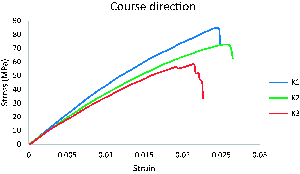

As can be observed, the strength of the K1 sample was more than that in other BWK composite samples in both wale and course directions. According to Table 1, the loop density in both directions of the fabric was more than that in other samples. Therefore, the volume fraction of the reinforcement part in the composite K1 was more than that in other samples. Increasing the loop density led to enhancing the volume fraction of fibers and improving the strength of the composite. When a tensile load was applied to the textile composite, fibers orientated through the load direction had a significant effect on the strength of the composite. Then, in the BWK composite the warp and weft yarns played the most important role in improving the strength of the composite. Increasing the loop density of the BWK fabric caused the increase in the number of warp and wale yarns and improved the strength of the composite. On the other hand, by enhancing the volume fraction of the fibers in the composite, the stiffness of the composite was increased as could be seen in Figures 9 and 10 for both directions.
The elastic modulus and strength of the composite for each sample in the wale direction were more than those in the other direction. The reason for this phenomenon was more presence of the fibers in the wale direction, as compared with the course direction.
Numerical results
In this study, a unit-cell of three kinds of the biaxial weft knitted composite was modeled in the ABAQUS software. Periodic boundary conditions were applied to each unit-cell. Figure 11 illustrates the stress contours of the matrix and the reinforcement part.
Stress contours for the unit cell of the composite structures: (a) matrix and (b) biaxial fabric.
Predicted stiffness matrices for all composites.

Stiffness matrices obtained from meso scale were used for the macro model. Figure 12 shows the stress–strain curve comparison between the experimental and FE modeling results.
Stress–strain curves for the FE and experimental results: (a) K1 composite in the course direction, (b) K2 composite in the course direction, (c) K3 composite in the course direction, (d) K1 composite in the wale direction, (e) K2 composite in the wale direction and (f) K3 composite in the wale direction.
Based on Figure 12, multi-scale modeling results showed a good agreement with the experimental results in predicting the elastic behavior of the composites. It can be concluded the mechanical behavior of the composite for the elastic section in different loop densities was predicted by using multi-scale modeling. For predicting the tensile strength of the BWK composites, the Tsai-Wu failure criterion was used to determine the tensile strength in both wale and course directions. In each increment that the Tsai-Wu failure criterion value equals to 1, the value of stress was reported as the tensile strength in each direction. Figures 13 and 14 illustrate the predicted strength for all samples.
Initiation of failure for all composites in the course direction (according to equation (8)): (a) K1, (b) K2 and (c) K3. Initiation of failure for all composites in the wale direction (according to equation (8)): (a) K1, (b) K2 and (c) K3.

Comparison of the experimental and numerical results, values are given as mean value (standard deviation) (the unit of all values is MPa, Error% shows the difference between experimental and numerical results for each output).

According to Table 6, more differences between experimental and numerical results in the strength values could be observed. These differences were due to some defects made during the manufacturing of composites such as bubbles in the composites. On the other hand, the degradation of yarns while applying load was not considered in FE modeling. However, in the elastic modulus, in both course and wale directions, a good agreement between the results was found. According to Table 4, the compressive strength obtained from equations (2) to (4) was the same as the tensile strength. No compressive strength value could be, however, chosen for the fibers used in equation (2). This is another reason for the differences between the experimental and numerical strength.
According to the results, by using multi-scale modeling, the mechanical behavior of the composite in different structures and loop densities could be predicted before the manufacturing. It could lead to the decrease of the production costs and waste of the materials during manufacturing. On the other hand, according to the final usage some, new composite structures could be designed and optimized by using multi-scale modeling.
Conclusion
In this study, the effect of the loop densities of the biaxial weft knitted composites on tensile behavior was investigated using both experimental test and the numerical method. According to the experimental results, the strength of the composites was improved by increasing the loop density in both course and wale directions. On the other hand, the elastic modulus of the composites was enhanced by increasing the loop density. For numerical analysis, multi-scale finite element modeling was employed to predict the elastic modulus and strength of the composites. The numerical results had a good agreement with the experimental ones. According to the numerical analysis, the warp and weft yarns played an important role in determining the tensile strength of the composite. So, a unit-cell of the textile composite could be created in the FE software to predict the elastic modulus and the tensile strength of the composite. On the other hand, the mechanical properties of the composites could be predicted in some different loop densities and complex shapes by using this modeling method. In addition, the bending and impact of the behavior of the biaxial weft knitted composite in different loop densities and different structures could be considered in the future works.
Footnotes
Declaration of conflicting interests
The author(s) declared no potential conflicts of interest with respect to the research, authorship, and/or publication of this article.
Funding
The author(s) received no financial support for the research, authorship, and/or publication of this article.