
Abstract
3D multi-cell spacer-knitted reinforced composites are composed of knitted layers which are joined together by multiple fabric connecting layers. Despite numerous capabilities, they demonstrate inferior bending performance due to their highly looped construction as well as low fiber volume fraction. Bending characteristics could be enhanced by inserting the warp and weft yarns through the fabric’s surface layers in wale and course directions. This research aims to investigate the role of reinforcing warp and weft yarns and structure profile on bending behavior of the composites produced from 3D multi-cell spacer-knitted fabrics. 3D multi-cell spacer-knitted fabrics were produced with rectangular cross-sectional shape in single- and double-decker profiles on a computerized flat-knitting machine. The surface layers of both 3D multi-cell spacer-knitted fabrics were reinforced by glass straight yarns in course and wale directions. The produced fabrics were used to fabricate thermoset 3D composites using epoxy resin via vacuum-assisted resin-transfer method. Composite samples were subjected to three-point bending load. Statistical analysis revealed that the composite profile and presence of the reinforcing warp and weft yarns affect significantly the flexural properties of 3D-knitted composites. Accordingly, introduction of the reinforcing straight yarns causes an increase in maximum bending force by 75 and 62.5% for single and double-decker structures, respectively. In order to understand how the tensile and compressive stresses are distributed on the 3D-knitted composite structure as well as to predict their mechanical behavior, a macro-mechanical model was created in the ABAQUS software.
Keywords
Introduction
3D textile-reinforced composites have vastly attracted the attention of numerous engineers due to their light-weighted structures as well as high mechanical performances. This attention mainly refers to some limitations of sandwich-reinforced composites in terms of their inferior thickness-through mechanical properties [1]. Moreover, laminating methods of 2D textile reinforcements create stress concentration in multi-layered structures which caused de-lamination phenomenon in composite constitutive layers [2]. Conventional 3D spacer fabrics which are commonly used for industrial applications are composed of two separate surface layers which could be connected together by pile yarns [3,4]. The surface layers of 3D spacer fabrics can be linked together by fabric connecting layers. This innovative spacer fabric is named multi-cell spacer-knitted fabric (3D-MCHKF) owing to creating a cellular structure. Among the different production techniques, weft-knitting represents high flexibility in designing 3D-MCHKFs with various geometrical shapes [3–5]. 3D-MCHKFs exhibit significant advantages such as higher mechanical performance and high potential for designing the complex shapes compared with conventional 3D spacer-knitted fabrics. These structures could be utilized as composite reinforcement in various areas such as automotive and aerospace industries as well as environmental protection [5].
Due to technical advancements in flat-knitting technology, it is being successfully employed in fabricating 3D-MCHKFs [4–6]. Figure 1 depicts the cross-sectional views of different 3D-MCHKFs which could be knitted on a flat-knitting machine.

Cross-sectional views of different 3D-MCHKFs [6]: (a) single decker profile; (b) double decker profile.
Despite the merits of these structures as composite reinforcements, limited researches have been conducted on evaluating and enhancing their mechanical performance. Abounaim et al. [5] introduced a method to fabricate thermoplastic composites reinforced with 3D-MCHKFs in rectangular cross-sectional shape. Hamedi et al. [6] predicted the bending behavior of a simple geometrically 3D multi-cell spacer weft-knitted-reinforced composite made of high-tenacity polyester yarns using multi-scale finite element method. Hassanzadeh et al. [7–11] investigated the bending and compression properties of 3D glass–epoxy composites produced by 3D-MCHKFs. They fabricated 3D-MCHKFs with four different cross-sectional shapes and infused epoxy resin through fabric structure via vacuum resin-transfer process. They reported that the produced 3D composites represent higher compression resistance compared to conventional-woven and warp-knitted spacer-reinforced composites. Also, the results revealed that the cross-sectional shape has significant effect on mechanical performance of the produced 3D-knitted composites.
Using advanced knitting techniques, Omrani et al. [12,13] produced tubular-shaped configuration of these structures and predicted their behavior under external static and internal hydrostatic pressures using finite element method. Low-velocity impact behavior of composites produced from 3D-MCHKFs using drop weight impact test was investigated by Azadian et al. [14,15]. Three different 3D-MCHKFs varying in their cross-sectional shapes were knitted from E-glass yarns and were then impregnated with unsaturated polyester resin via VARTM method. The surface layers were then reinforced with six woven reinforced composite layers. The results showed that the cross-sectional shape has significant effect on the low-velocity impact behavior of the produced composites. They also concluded that matrix crack-formation in face-sheets and transversely propagated cracks at the connecting layers of composite structure are responsible for failure under drop weight impact test.
Verpoest et al. [16] suggested that the stiffness of knitted fabrics is relatively low compared to other textile structures which in turn are attributed to the looped, curved architecture of the fibers. For this reason, previous researches conducted on multi-cell knitted spacer-reinforced composites reported relatively low bending strength due to using the plain-knitted structure as surface layers. Ramakrishna and Hull [17] showed that, at constant fiber volume fraction, the introduction of uncrimped yarns which are preferentially oriented through knitted structure in course and wale directions can significantly enhance the mechanical properties.
Despite valuable experimental studies being conducted as stated above, investigating the effect of reinforcing yarns on bending behavior of multi-cell knitted spacer-reinforced composites has not been investigated yet. For providing a complete report regarding their bending behavior, 3D-MCHKFs were produced in single and double-decker cross-profiles, and their constitutive surface layers were reinforced with warp and weft yarns in course and wale directions. This research undertakes to examine the role of reinforcing straight yarns as well as structure profile on bending behavior of the 3D multi-cell spacer-reinforced composites. Also, in order to achieve a further insight into the response of these composite structures under bending loading, finite element method was applied.
Materials and methods
3D fabric production
Using four-ply of 100Tex E-glass yarns, 3D-MCHKFs with rectangular cross-section in two different profiles namely single-decker and double-decker were produced on a computerized Stoll flat-knitting machine (CMS-400, E5, equipped with latch needles, four systems, and closed carriage).
The six-step knitting techniques required for producing the 3D-MCHKFs with single-decker profile have been depicted in Figure 2. In the first step, the alternate needles in both front and rear needle-beds are individually participated to create top and bottom surface layers. This operation can be repeated for fabricating the knitted courses of surface layers based on desired length. The first course of crosslink formation between the surface and connecting layers is provided during step 2. To this end, the knitting operations are carried out on all needles of front needle-bed. Continuing the process, single-jersey knitting is performed on odd needles of the front needle-bed which leads to create connecting layer. In this step, the numbers of knitted courses determine thickness of the final 3D structure. As the final step, to create the junction between both surface layers and connecting layer, the last knitted course of the connecting layer must be transferred to corresponding needles of the rear needle-bed. Prior to this operation, racking of the rear needle-bed is carried out in such a way that the odd needles of the front needle-bed could be face to face with the even needles of the rear needle-bed. Finally, before starting a new procedure, the needles of rear needle-bed should be racked back to their original position.

Six-step knitting techniques required for producing the 3D-MCHKFs with single-decker profile.
As can be seen in this illustration, 3D-MCHKFs consist of two surface layers as well as multiple connecting layers which are commonly knitted on individual front or rear needle-beds. In order to reinforce their surface layers, 1200Tex E-glass yarns were straightly inserted through each wale and course of MCHKF’s surface layers. To lay the weft yarn through the knitted structure, a yarn feeder is pulled along the needle-beds without raising the needles. For inserting the warp yarns, a special yarn feeder is needed [18,19]. Plain-knitted structure reinforced by straight yarns in course and wale directions is technically named as biaxial plain weft-knitted fabric. The operations required for introduction of straight yarns in surface layers of MCHKFs have been described elsewhere [4,5].
Overall, four composite samples varying in cross-sectional shape and reinforcement of fabric’s surface layer were produced. The produced composite samples and their specifications such as profile type, layer’s structure, loop density, and areal density are provided in Table 1. Figure 3 depicts the cross-sectional views of the produced 3D-knitted performs.
Characteristics of produced MCHKFs.

aCourses per centimeters.
bWales per centimeters.

Cross-sectional views of the produced MCHKF’s: (a) RSU; (b) SU. single decker profile: (a) reinforced knitted surface layers; (b) plain knitted surface layers; (a) RDU; (b) DU. Double-decker profile: (a) reinforced knitted surface layers; (b) plain-knitted surface layers.
Due to brittleness of glass fibres, optimized adjustments such as fabric take-down mechanism, machine speed, and loop length are essential to prevent the unwilling yarn breakage during knitting as proposed in Hassanzadeh et al. [7]. During the loop-transfer process, length of the transferred loops is also a critical factor affecting the fabric quality; comparatively, longer loops would guarantee a precise and flawless loop-transfer process. The prepared samples underwent dry relaxation for 24 h, according to ASTM D578 prior to composite manufacture.
Composite manufacturing
The 3D composite samples were fabricated via VARTM method due to its ability to manufacture high-quality composite parts in complex geometrical shapes. More details about the VARTM method are depicted in Figure 4.
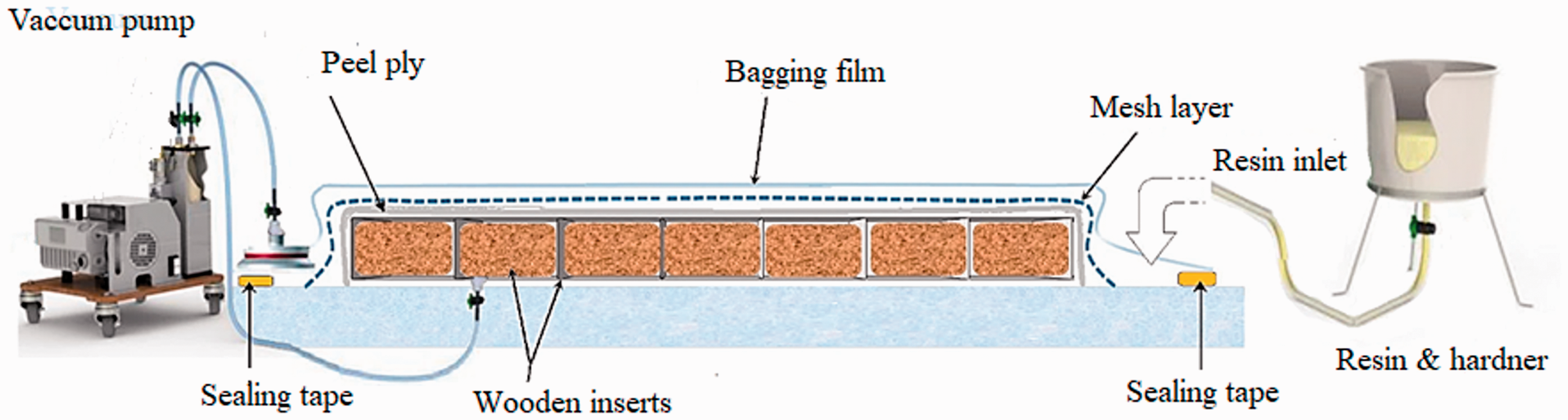
Illustration of VARTM method for composite manufacturing.
As shown in Figure 5, epoxy resin was infused through 3D-knitted preforms via a four-step manufacturing process. Prior to applying the vacuum by negative pressure pump, free spaces between the fabric’s layers should be occupied with auxiliary inserts in order to remain unchanged during manufacture process. These auxiliary inserts will be pulled out after curing process. In order to ease their pulling out from the preforms after composite curing process, the inserts were covered with releasing wax, prior to insertion.
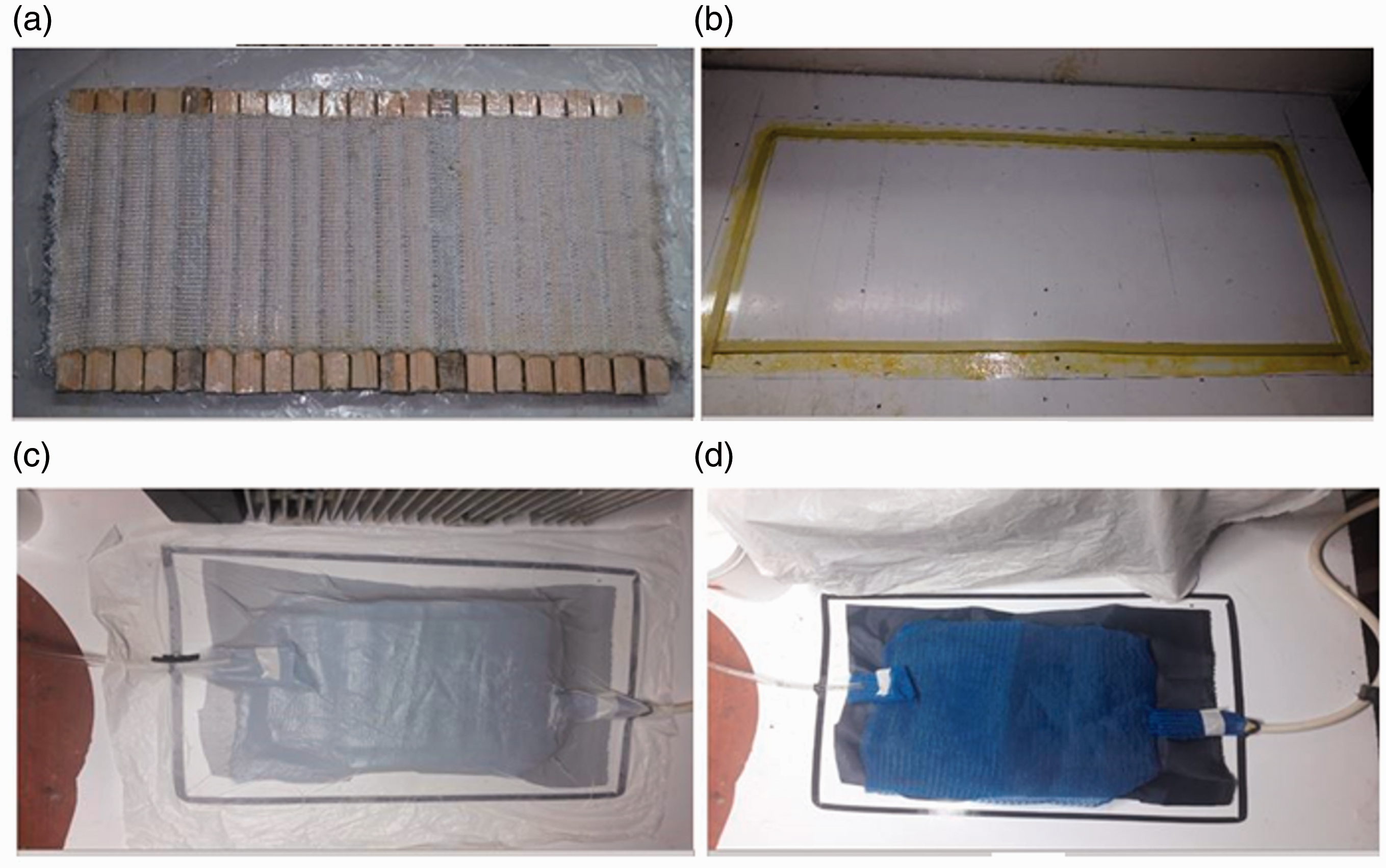
Manufacturing process of 3D multi-cell spacer knitted reinforced composite.(a) locating the wooden inserts through the spacer fabric; (b) surface preparation via release agent coating with sealant tape covering; (c) covering the fabric sample with peel-ply and mesh layers; (d) covering the plastic bag on the mesh layers and applying vacuum pressure.
Some of the resin specifications are given in Table 2. Prior to injection, two components of resin were mixed in 100 pbw:10 pbw ratio. Composite curing was carried out in room temperature for 48 h. To achieve higher mechanical characterizations, composite samples were post-cured for 3 h in an oven at 80°C. Figure 6 shows the produced composite samples with their dimensions.
Properties of the used epoxy resin.


Produced composite samples: (a) single decker; (b) double decker.
Fibres volume fraction 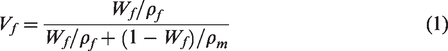
Although using the VARTM method to produce the composite samples would lead to form lower void content, but the possibility of void formation during composite fabrication could not be undeniable [7]. Equation (2) gives the value of void content, in which Td is the theoretical density of composite and Md is the experimental density of composite samples. Accordingly, the void contents for composite samples SU, RSU, DU, and RDU were 0.92, 1.05, 1.2, and 0.96%, respectively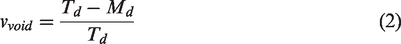
Mechanical characteristics of yarns and knitted composite
Tensile properties of the E-glass yarns
Tensile characteristics of the used E-glass yarns measured according to ASTM D2256 are given in Table 3.
Specifications of E-glass yarns used for fabric production.

Flexural test of 3D-knitted composites
The standard flexural test method (ASTM C 393) was used to investigate the behavior of 3D spacer composite samples under three-point bending loading. Schematic views of this test are shown in Figure 7. Additionally, the tests were carried out in standard conditions (22 ± 3°C and 50 ± 5% r.h) in order to eliminate the effect of content moisture.
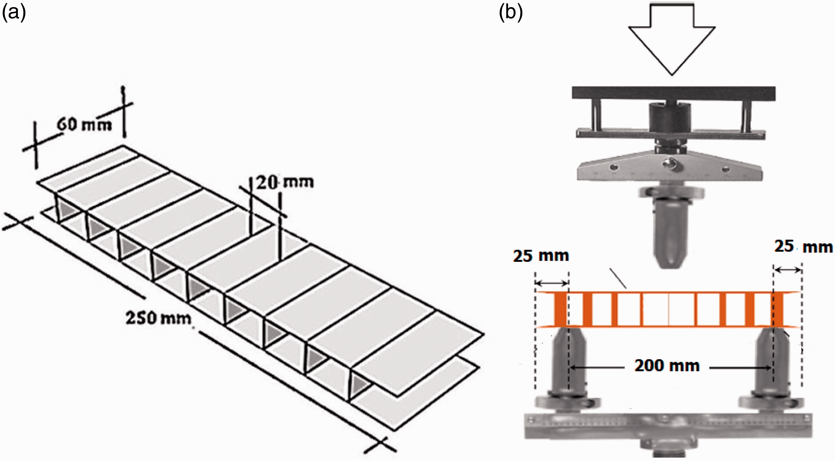
(a) The specimen’s dimensions and (b) three-point bending test apparatus.

Defining the directions of wale and course for surface and connecting layers in 3D model.

Boundary conditions considered for each component during bending process.
Tensile tests of knitted composite
For finite element modeling, elastic modulus of composite layers in warp and weft directions as well as Poisson ratio should be measured. The standard tensile test method (ASTM D3039) was used to evaluate the tensile properties of the plain-knitted and biaxial-knitted-reinforced composites using a Tinius Olsen tensile tester (Model H25KS).
Shear test of knitted composites
For simulating the bending behavior of the produced 3D composite, determination of shear modulus of the composite layers is required. ASTM D7078 (V-notched rail shear method) covers the determination of the shear properties of high-modulus fiber-reinforced composite materials by clamping the ends of a V-notched specimen between two pairs of loading rails. When loaded in tension, the rails introduce shear forces into the specimen through the specimen faces.
Finite element modeling
In order to understand how the compressive and tensile stresses are distributed on the composite layers during bending process, finite element method was employed. Finite element modeling of the textile composites is commonly carried out in meso and macro scales. Due to structural complexity of knitted-reinforced composites, the meso modeling needs complicated simulation and takes a lot of time. Also, computational cost of this model is higher than macro model. Hence, in this modeling approach, 3D knitted-reinforced composite was considered as a continuous material. Although this assumption has no high conformity with reality, it can help us in analyzing the stress distribution on the composite structure by spending less time and cost. The ABAQUS software was used to simulate the three-point bending test. The steps of finite element modeling are explained as follows: The 3D composite specimen was considered as deformable shell structure. Conversely, the components associated in three-point bending loading such as indenter and supports were defined as 3D analytical rigid. The 3D model was designed according to the real dimensions of the composite samples. Figure 7(a) depicted the geometrical model created in ABAQUS software environment. Engineering constants, density, and thickness of the composite layers.

Afterward, due to different spatial orientation of knitted loops in surface, middle, and connecting layers, directions of the wale and course should be defined for all model’s layers (Figure 8).
In the “interaction module,” the contact between the model components is defined, so that each component can identify the boundary of the other components during loading process. Surface-to-surface contact was chosen for defining the contact type of the model components. The contact between the rigid bodies (indenter and supports) and the 3D composite was established by a frictionless interaction.
Also, the required boundary conditions were considered for each component (indenter and supports) during bending process as depicted in Figure 9. The supports were restricted in the X, Y, and Z directions and could not rotate around X-, Y-, and Z-axis. The indenter was restricted in the X and Z directions and could not rotate around X-, Y-, and Z-axis.
In the next step, meshing phase was conducted. The meshed shell element consists of 1266 reduced integration linear quad elements with average size of 2 mm. Using different mesh sizes from 4 to 1 mm, it was concluded that the simulation results are not affected by changing in mesh size.
Solving the problem was carried out using the explicit numerical method. The final model contained 1266 elements which took 20 min on a dual core computer with two 2.7 GHz processors.
Results and discussion
Tensile properties of composite’s surface layers
As a result of bending process, the top surface layer of the 3D composite structure is subjected to compression and the bottom surface layer to tension. It is reasonable to suppose, therefore, that the connecting layers are the zones at which the stress is zero. Therefore, prior to perusing the bending behavior of the 3D composite, it will be helpful to first have a discussion on the tensile properties of surface layers which are composed of plain-knitted or biaxial-knitted structures. It can certainly help to better understand the effect of the straight yarn reinforcements on the bending performance of the produced composites.
Figure 10 depicts the stress–strain curve obtained from the plain-knitted reinforced composites and biaxial weft-knitted reinforced composites in course direction. Both composite structures can be compared to each other considering three features extracted from the stress–strain curves namely initial slope, stress, and strain at fracture point.

Tensile stress–strain curve of the composites reinforced with plain-knitted and biaxial weft-knitted fabrics.
From these curves, it can be observed that tensile stress of biaxial weft-knitted composites increases linearly with increasing strain rate, and it is followed by a sudden drop in the applied stress which refers to ultimate failure of the composite. Indeed, the reinforcing straight yarns are subjected to tensile loading before the knitted loops start to be elongated. Failure of the straight yarns takes place at the stress which cannot tolerate by the plain-knitted structure due to its low strength. This means that ultimate stress and strain of the composite samples are mostly determined by the straight yarns. Consequently, composite sample behaves as a brittle material meaning a linear behavior along with low fracture strain. Although the straight yarns inserted in wale direction do not associate in load bearing, they affect the failure strength of the composite structure via increasing the fiber volume fraction and yarn interlacing. In comparison, the plain-knitted reinforced composite presents a non-linear curve as well as low stiffness. Such a behavior can be explained by Krenchel model [22], proposed for knitted-reinforced composites. The efficiency of a curved fiber in load carrying is defined as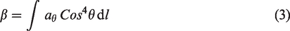

Flexural properties of 3D-knitted spacer composites
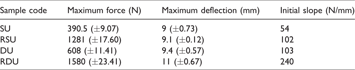
Table 5 represents the mechanical characteristics of the composite samples after three-point bending test. Flexural test on composite materials is generally carried out to characterize their bending stiffness, bending strength, core shear strength, and shear modulus. In order to investigate the effect of reinforcing the composite surface layers by straight yarns on their bending behavior, both composites produced in single decker profile (SU and RSU) were compared in terms of bending stiffness and bending strength.
Characteristics of the composite samples resulted from three-point bending test.
Figures 11 and 12 show the deformation stages of composite samples SU and RSU during bending process resulted from both experimental and simulating methods. As can be observed from the force–displacement curves, the load increases linearly with sample deflection until the composite structure is totally deformed under applied force. During bending process, composite’s top facing experiences compressive stresses while the bottom facing is subjected to the tensile stresses. The connecting layers will remain undeformed for loads less than the critical load which is defined as

Deformation of the 3D-knitted spacer composite (sample SU) under bending load.

Deformation of 3D-knitted spacer composite reinforced with straight yarns (sample RSU) under bending load.
According to the standard method, sample deflection (Δ) which is appeared during bending process can be derived from equation (5)


Force–displacement curve of the composite samples (SU, RSU) under bending loading.
The effect of reinforcing the surface layers of the 3D composites on their bending behavior was also studied for double-decker profile (DU and RDU samples). Figures 14 and 15 show the deformation stages of both composite samples during bending process.
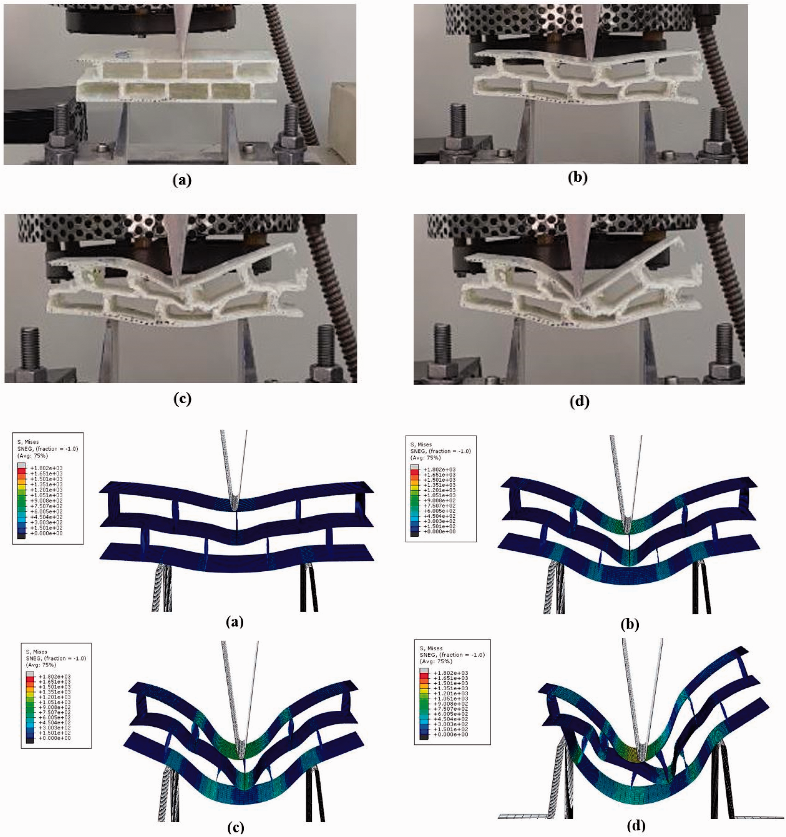
Deformation stages of the DU composite sample under bending loading.

Deformation of the RDU composite under bending loading.
In the first stage of the bending process, the force required for sample deflection is increased linearly corresponding to loading knife’s displacement. Simulation results depicted in Figures 14 and 15 show vividly the stress concentrated on the top and bottom surface layers. The force applied to the top facing leads to the top facing’s wrinkling which is transferred to middle and bottom layers by vertical connecting layers. After deformation of thin middle layer, the force–deflection curves increase with a smooth slope. Following the deformation of thin middle layer, the vertical connecting layers start to buckle. Further increasing the sample deflection causes top facing and core failure which is followed by the sudden drop of the curve. More deflection leads to slightly increasing of the applied force, which is resulted from layers consolidation. As already discussed, most of the applied external energy is absorbed by bending the top and middle layers as well as buckling the connecting layers; therefore, the observed damage in bottom facing is less than top facing.
Comparing the initial slope of both force–displacement curves (Figure 16), it is obvious that RDU composite structures possess significantly higher bending stiffness as well as higher strength than the DU sample. This obvious difference is attributed to the presence of the straight yarn in surface layers for RDU sample. Also, bending force of RDU composite shows an increase of 60% compared to the 3D composite reinforced with plain-knitted fabric (sample DU).

Force–displacement curve of composite samples DU and RDU under bending loading.
Due to higher number of connecting layers in the composite having double-decker profile, the force required for bending is greater than single-decker composite. Also, due to higher thickness of double-decker composites, more deflection was observed during bending process in comparison to single-decker composites. This feature makes double-decker composites a good candidate for energy absorption.
Two-way ANOVA analysis was used to study the significant effect of composite profile as well as reinforcing straight yarn on the bending strength of the 3D multi-cell knitted spacer composites. Table 6 shows the results of this analysis. The outcomes revealed that the composite profile and reinforcement have significant effect on the bending strength.
Results of ANOVA analysis.

aR-squared = 0.950 (adjusted R-squared = 0.931).
Validation of the simulation results
In current research, the numerical modeling was carried out without applying the fracture mode. Thus, this approach cannot predict the bending behavior of the 3D composite structure after fracture. Figures 17 and 18 depicted the force–displacement curves extracted from experimental and simulation methods for both single and double-decker composites. The results revealed that the proposed modeling approach can acceptably predict the composite’s behavior. The results also demonstrate that the force–displacement curve of double-decker samples has more conformity with simulation results in comparison to single-decker samples. In order to achieve more accurate results, multi-scaled (meso–macro) modeling is proposed.

Comparison between force–displacement curves extracted from experimental and modeling methods for single decker composite samples.

Comparison between force–displacement curves extracted from experimental and modeling methods for double-decker composite samples.
Conclusions
Studying the effect of composite profile and reinforcing the surface layers on bending behavior of 3D multi-cellular spacer weft-knitted composites results in some conclusions as follows: Bending performance of 3D multi-cell spacer-knitted composite is mainly affected by the facings’ tensile and compressive strength together with the core shear strength and modulus. The dominant fracture mode for 3D multi-cell spacer-knitted composite produced with rectangular cross-sectional shape was top facing wrinkling, crack propagation in bottom facing layer as well as buckling the thin middle layers (in double-decker structure). Regardless of composite structure, inserting the straight yarns through the composite facing layers causes an increase the tensile and compressive load carrying and consequently provides higher bending stiffness and modulus as compared with the conventional multi-cell spacer-knitted composites. Accordingly, reinforcing with straight yarns increases the maximum bending force by 75 and 62.5% in single and double-decker structures, respectively. Therefore, this technique can significantly enhance the bending behavior of 3D multi-cell spacer-reinforced composites. Statistical analysis results revealed that the 3D composite profile and reinforcing straight yarn have significant effect on the bending force as well as bending deflection. 3D multi-cell spacer-knitted composites produced in double-decker shape represent higher bending stiffness and strength as well as toughness. This means that these 3D composite structures could be employed where the energy absorption is important.
Footnotes
Declaration of conflicting interests
The author(s) declared no potential conflicts of interest with respect to the research, authorship, and/or publication of this article.
Funding
The author(s) received no financial support for the research, authorship, and/or publication of this article.