
Abstract
A nanofibrous microfiltration membrane with high flux, low pressure drop, and high retention capacity was fabricated by pore filling of copolyetherester nanofibers (low-melting-point polyester; melting point of 110℃) into a poly(ethylene terephthalate) nonwoven scaffold. Short low-melting-point polyester nanofibers were anchored on the surface of the poly(ethylene terephthalate) fibers by heat treatment to form a crosslinked nanostructured mesh with very high porosity and high specific surface area. The pore size and distribution of the membranes can be adjusted by varying the loading amount of nanofibers. The resulting membrane not only possessed good interception ability for 5, 3, and 1.3 µm polystyrene microspheres but also exhibited desirable water permeability. In the circulating filtration test, with the accumulation of membrane fouling in the filtration, the membrane was also effective in retaining particulate matter while improving the antipollution ability. These properties are desirable for the effective removal of pollutants on the membrane and restoration of the membrane flux.
Keywords
Introduction
Shortage of global drinking water and increasing water pollution require the development of highly efficient water purification techniques [1–3]. Among the current strategies, porous membrane is widely used for solid–liquid separations involving aqueous streams. This method has been a practical separation technique for many years due to technical advantages, such as gentle conditions, no phase change, the absence of additives, low energy expenditure, compact design, and ease of scale-up. To date, porous membrane is widely used in biotechnology, electronics, and chemical and food industries to separate particulate matter from the suspensions [4–7]. Conventional microfiltration (MF) or ultrafiltration (UF) filters for water treatments are based on porous membranes, typically manufactured by the phase immersion method. Their performance relies on their geometrical structure of pores, corresponding pore size distribution, and undesirable macrovoid formation across the entire film thickness. Usually, porous polymeric filtration membranes have their other intrinsic limitations, e.g., poor permeability, high operating pressures, limited available materials, cost effectiveness, and environmental concerns [8–10].
Nonwoven fabrics (NFs) are composed of a random network of staple fiber (short) or long fibers (continuous long). With the characteristics of connected pores, NFs are extensively used in dust and liquid filtration for the removal of particles larger than 1 µm during decontamination. The advantage of using nonwoven as filtration media is that the fiber configuration can be arranged according to the required pore size and its distribution, thereby maximizing the filtration efficiency depending upon the particular filtration mechanism involved [11–14].
When the diameters of fibers are decreased from micrometer (e.g., 10–100 µm) to submicron or nanometer (e.g., 10 × 10−3–100 × 10−3 µm), the nanofibrous nonwovens (NFNWs) reveal special properties due to the extremely high surface-to-weight ratio compared with conventional nonwovens [15,16]. The small pore size, high porosity, and large surface area with respect to the mass make NFNWs suitable for a wide range of water treatment applications, particularly in MF [17–20]. These mats have been proposed as alternative filtration materials for MF and UF membranes and as support layers in nanofiltration. They show various advantages such as high selectivity, hydrophilicity, and permeability compared with other polymeric membranes [21–23]. However, NFNWs are currently faced with the limitations of low productivity of nanofibers, mainly produced by electrospinning, and low poor mechanical strength, coming from low fiber strength and high porosity compounded with weak bonding at fiber junctions [24–26].
Several methods have been applied to convert quasi 2D electrospun mats into genuine 3D structures [27]. To fabricate a 3D nanofibrous structure, an electrospun nanofiber mat needs to be converted first into short individual nanofibers and/or tiny pieces (typically through mechanical stirring/grinding), which are then utilized as building blocks for the construction of 3D structures via freeze-drying technique [28]. Owing to the advantages of extremely low density, very high flux, and excellent separation efficiency, 3D structures have attracted growing research interests for various applications, including oil/water separation, sewage purification, catalyst support, and spongy gel [27, 29, 30]. However, during the fabrication process, the nanofibers have low strength and separation of electrospun nanofibers is difficult.
In this study, novel quasi 3D nonwoven scaffolds composed of nanofibers and microfibers were prepared by a simple wet-laid process and hot-press treatment. Poly(ethylene terephthalate) (PET) staple fibers and copolyetherester nanofibers with melting point of 110℃ (LPET) were used. With the aid of wet-laid process for manufacturing the NFs, short solution-blown low-melting-point polyester (LPET) nanofibers were uniformly filled into the openings of PET fibers to form a quasi 3D structure. The structures were partially melted by hot-press treatment to form tight connections among the fibers. The pore-filled nanofibers resulted in decreased pore size and distribution. The nonwoven fibers with different gram weights were characterized in terms of pore size distribution, fiber thickness, and mechanical properties. The filtration performances were also evaluated and compared with a commercial MF membrane.
Experimental
Materials
LPET with a melt point of 110℃ was supplied by Shenzhen Haian Plastic Chemical Co., Ltd. [31]. The staple PET fibers (the fineness is 1.5 D and the length is 6 mm) were provided by Shanghai FuYan International Trade Co., Ltd. Trifluoroacetic acid (TFA) and isopropyl alcohol were purchased from Tianjin Fengchuan Chemical Reagent Technology Co., Ltd. All of the above chemicals were used without further purification. The polyamide (PA) commercial MF membrane with pore size of 0.45 µm obtained from Haiyan New Oriental Plasticization Technology Co., Ltd. was selected for comparison.
Solution blowing of LPET nanofibers
A purpose-built solution blowing set-up was used for fabricating LPET nanofibers. During spinning, LPET was dissolved in TFA to obtain the spinning solution. Then, the spinning solution was feed to the orifices, and the heated compressed air was supplied to the slots [32]. After the solution streams are pressed out of the orifices, they are stretched to nanofibers by the high-velocity gas flow. The air pressure supplied to the slots was 0.5 bar, and the solution concentrations were 10, 15, and 20 wt%.
Fabrication of fibrous MF membrane
LPET nanofiber dispersion was prepared by mechanical cutting at 0.157, 0.314, 0.471, and 0.628 g of solution-blown nanofibers in 1000 mL of water/isopropanol mixture (50:50 by volume) with a modified standard fiber dissociator (Shandong Animaite Instrument Co., Ltd., Falcon 007 special electric steel blade) at −4℃ [33,34]. Then, 1.8 g of PET microfibers and 2000 mL of water were added to form blend fibrous pulp. A paper cup machine was applied to deposit the fibers onto a filter screen with a diameter of 20 cm and hot pressing at 110℃ and 50 N cm−1 to form fibrous MF membranes (FMFMs, Figure 1). The preparation of FMFMs with 0.157, 0.314, 0.471, and 0.628 g nanofibers were labeled as NF-5, NF-10, NF-15, and NF-20, respectively. The PET nonwoven scaffold was labeled as PS-0.
Schematic of the fabrication for the FMFM.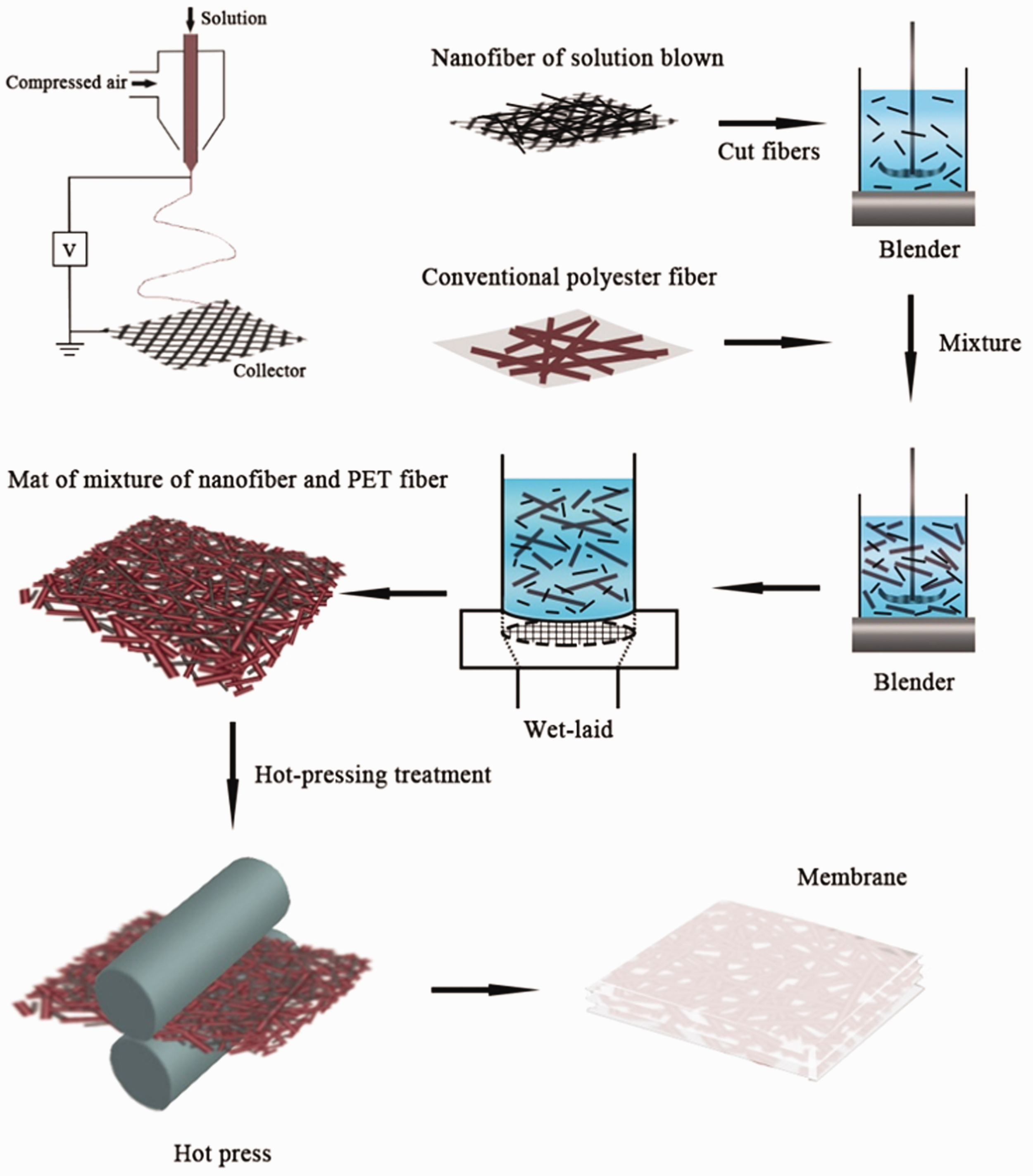
Fibrous membrane structure and property characterization
Scanning electron microscopy (SEM) analysis
The morphology of the nanofibers and the surface and cross-sectional structure of the membrane were characterized using a scanning electron microscope (Hitachi S4800, Japan) after sputtering with gold.
Zeta electric potential
Dispersion properties of short nanofibers in solution were analyzed by zeta potential ζ (Mastersize 3000, Malvern). The as-prepared short nanofibers were dispersed in a mixed solution of absolute ethanol and water (1:1) at a concentration of 0.0005 g/mL at temperature of 25℃, and the zeta potential ζ was reported automatically.
Mechanical characterization
After hot pressing, the tensile strength and elongation at break of the membrane were characterized using an Instron universal testing machine (Instron3369, USA) at a crosshead speed of 1 mm/min. Following the standard shape requirements, the effective length and width of the samples were 2 and 0.4 cm, respectively [35]. All the measurements were tested three times at room temperature.
Determination of porosity (%) and pore size
The pore sizes of the membrane were measured with a 3H-2000PB Bubble Pressure Aperture Analyzer, which was able to probe pore sizes in the range of 0.02–500 µm. Pore size was measured for five times to calculate the average.
The porosity (ɛ) is the proportion of the volume of void to total volume of the membrane and calculated using the following equation
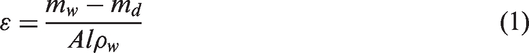
In the formula, mw is the weight of the wet membrane (g), md is the weight of the dry membrane (g), A is the effective area (cm2), l is the thickness (cm) of the membrane, and
Measure of contact angle
The hydrophilicity measurement was carried out by a contact angle goniometer (JYSP-180, Jinshengxin Testing Machine Co. Ltd., China). The nonwoven was tiled in turn on the platform of the contact angle goniometer. Then, precisely controlled 0.1 Å water droplet (1.0 µL) was dropped onto the surface of nonwoven by using a microliter syringe. During this process, three random locations of the nonwoven material were selected to measure the contact angles; the average values were calculated using a software application to minimize experimental error for each sample. Ten pictures were obtained in 10 s after water was dropped onto the surface. All the tests were conducted at room temperature.
Water flux and particle rejection analysis
As Figure 2 shows, the experiments of water flux and particle rejection efficiencies of the membrane were conducted under an assembled dead-end stirred cell system determined by using the deionized water and polystyrene particle with a size of 5, 3, and 1.3 µm (Tianjin Unibead Scientific Co., Ltd.). The effective area of the membrane was 19.625 cm3, and during the measurement, a variable-speed diaphragm pump (DP-130, Xinxishan Industrial Co., Ltd.) was used to control the transmembrane pressure. The membrane was cut and tightened on the film pool and then fed into deionized water. Subsequently, the pressure was adjusted to 0.1 MPa to begin the flux test by using the following equation
Schematic illustration to devise a water flux and particle rejection measurement.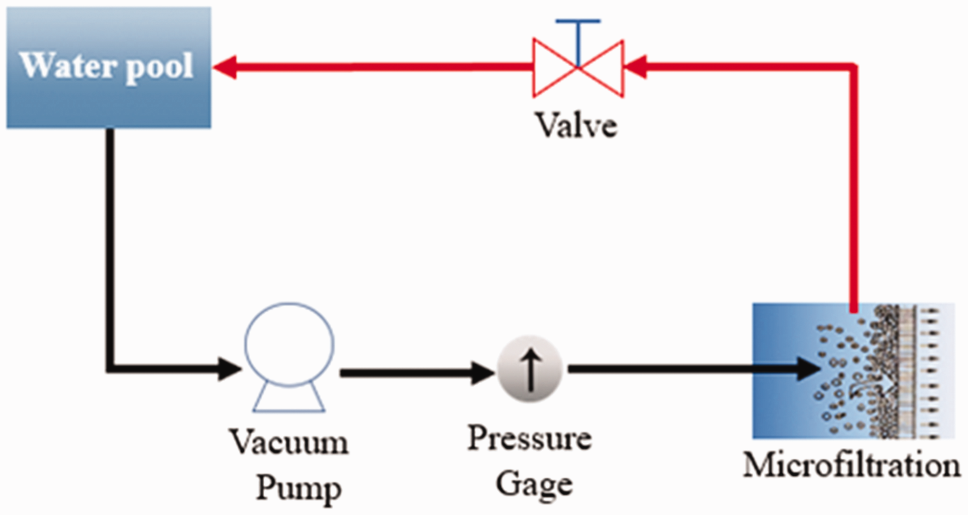


Antifouling performance of the membrane
The contaminated condition of the membrane was evaluated via the following method, wherein

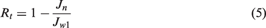
Especially, three ratios are available to further analyze the fouling condition of the membrane. Rt is the entire flux loss caused by all fouling and obtained via the following equation


Result and discussion
Dispersion of solution-blown LPET nanofibers
In the study, the FMFMs achieve the pore structure control via wet laying by pore filling the openings of PET nonwoven scaffold. Therefore, well dispersing is vital to realize the abovementioned structure. In solution blowing, nanofibers are obtained by shearing force at the solution/gas interface at high-speed airflow. In addition, the fibers show three-dimensional-crimped morphology due to subsequent bending instability and turbulent air flow around the polymer jet. Figure 3 shows the morphology of LPET nanofibers at different concentrations. When the solution concentration is 10 wt%, the nanofibers were ultrafine with average diameter of 0.395 µm, were in the 3D morphology, and were entangled together. With the increase of the solution concentration, the crimpness of fibers gradually reduced. Most fibers were straight when the solution concentration was increased to 20 wt%. This condition was helpful to improve the dispersion of nanofibers. According to the statistical data, the nanofibers obtained large diameter with the increase of the spinning solution concentration. The obtained fibers mainly ranged from 0.4 to 1.2 µm under the condition of 20 wt%, and the average diameter was 0.859 µm.
Morphology of LPET nanofibers by solution blowing at different concentrations (a) 10 wt% LPET, (b) 15 wt% LPET, and (c) 20 wt% LPET. (d) Morphology of short LPET nanofiber. (e) The diameter distribution of (c). (f) The aspect ratio distribution of short LPET nanofibers. (g) The length distribution of short LPET nanofibers and suspended short LPET nanofibers with concentration of 0.001256 g/mL.
To obtain a short fiber suspension, 20 wt% LPET nanofibers were dispersed in a mixture of 2-propanol and deionized water (1:1 volume ratio) at −4℃ and sheared for 10 min by using a standard fiber disintegrator. As shown in Figure 3(d), (f), and (g), the nanofibers were successfully cut into short nanofibers, with a length distribution of 40–160 µm and an aspect ratio distribution of 50–150. The zeta potential was measured to be 905 mV at a concentration of 0.0004 g/mL at 25℃. This result indicated that the short nanofibers have good dispersibility.
Structure of the FMFM
The 1.8 g PET fibers and 2000 mL water were added to the short-cut LPET nanofiber dispersion and were further dissociated for 3 min to obtain blend dispersion and deposited on the web. Figure 4(a) and (b) illustrates the formation of nanofiber meshes in the pores and the changes after hot pressing. Figure 4(a) illustrates that the limiting case of complete nanofiber dispersion, forming a crosslinked 3D network, loosely fills the space within the PET nonwoven scaffold. Figure 4(b) shows the limiting case of complete nanofiber crosslinked in the PET nonwoven scaffold.
Schematic of the formation of the nanofiber mesh in the PET nonwoven scaffold: (a) infused short LPET nanofibers forming loose mesh; (b) short LPET nanofibers crosslinked forming fibrous membrane by hot pressing. (c) SEM images of FMFMs by pore filling of nanofibers into PET nonwoven scaffold before hot pressing; (d) SEM images of short LPET nanofiber-modified PET nonwoven scaffold after hot pressing.
The result showed that the effective surface area of the fibrous membrane has significantly increased compared with the nonwoven scaffold. As shown in Figure 4(c), a part of the short LPET nanofibers would adhere to the PET fiber support. The other parts would be interconnected in the pores of the PET nonwoven scaffold to form a filling structure, which can effectively regulate the pore structure. After heat treatment at 110℃, the LPET was partially melted to achieve bonding for solidification of the pore structure. Figure 4(d) shows the characteristic of these two cases, that is, some LPET nanofibers form anchor points on the surface of the stent, and the rest would fill the space and partially melt to form crosslinked network structure. This condition effectively improved the pore size distribution of the membrane.
In addition, the FMFMs can be used as a MF membrane with excellent mechanical property and durability. Figure 5 shows the stress–strain curves of FMFMs with different nanofiber contents at room temperature. By contrast, the NF-5 to NF-20 films remarkably enhanced the mechanical properties of the membrane. A higher nanofiber content resulted in better mechanical properties. For instance, PS-0 showed a maximum stress of 3.9 MPa, and the tensile strength of the NF-5 to NF-20 were gradually increased to 7.9, 9.6, 10.9, and 11.1 MPa with increasing nanofiber contents. Compared with polyvinylidene fluoride (PVDF) flat membrane (1.85 MPa), the FMFMs prepared from the mixture of short nanofibers with other materials showed further improvement in mechanical properties. In addition, the stress–strain curves of NF-5 and NF-10 were fluctuant, which can be due to the uneven stress caused by insufficient nanofiber content. As a result, the strength of the FMFMs was greatly improved, suggesting that the nanofibers provided an effective reinforcement. The NF-20 membrane showed that highest strength.
Tensile strength of FMFMs with different contents of LPET nanofibers. (The dashed line is tensile stress of PVDF flat membrane [37].)
Effect of nanofiber loading content on pore size
As can be seen in Figure 6 and Table 1, the diameter of the PET staple fiber is in the micron range. The pore diameter of the nonwoven composed of PET staple fiber is relatively large and widely distributed, with an average pore size of 55.60 µm and porosity of 43.2 ± 1.7%. After filling the nanofibers, the pore size distribution and pore size of the membranes gradually decreased, whereas the porosity increased. At nanofiber content of 5 g/m2, the mean pore size of the membrane was 53.34 µm, and the porosity increased to 51.6 ± 2.1%. With the increase of the nanofiber content, the pore size of membranes gradually reduced. The mean pore size of the membrane was reduced to 15.29 µm when the nanofiber content reached 20 g/m2, and the porosity is 66.4 ± 1.9%. The pore size distribution became narrow, and the integral flow rate was 38.7% under the pore size of 15.1 µm. Owing to the large pore size of the FMFMs, the water permeation performance of membranes was excellent, and the contact angle of all membranes was 0°, thus showing good hydrophilicity.
Pore size distribution of FMFMs with different contents of LPET nanofibers. Pore sizes of the FMFMs. FMFM: fibrous microfiltration membrane; NF: nonwoven fabric; PS: poly(ethylene terephthalate) nonwoven scaffold.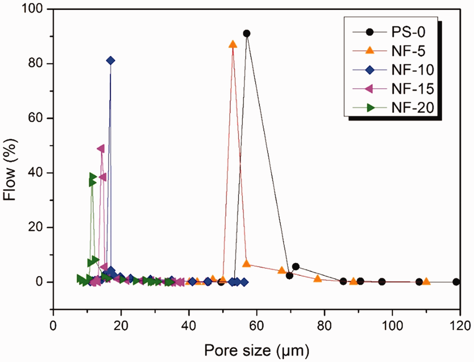

Evaluation of MF performance
The monodispersed polystyrene microsphere solution was prepared to test the filtration performance of the membranes. All membranes were compacted with deionized water at 0.15 MPa for 5 min. Then, the pure water flux and particle rejection tests were measured at 0.1 MPa. As shown in Figure 7, compared with the nonwoven prefilled nanofiber scaffold, the membrane flux decreased from 444.3 L/m2 min (PS-0) to 390.3 L/m2 min (NF-5), 375.1 L/m2 min (NF-10), 366.9 L/m2 min (NF-15), and 360.7 L/m2 min (NF-20), with a maximum NF-20 flux reduction of 18.8%. Compared with the LPET nanofiber membrane (196.1 L/m2 min, 0.1 MPa) and PA MF membrane (103.9 L/m2 min, 0.2 MPa), FMFMs have high water permeability. However, importantly, Figure 8 shows the rejection efficiencies of nanofiber-filled FMFMs for 5 µm polystyrene microspheres increased from 92.5 ± 0.97% to 99.9 ± 0.2%. For 3 µm polystyrene microspheres, the rejection efficiencies increased from 90.22 ± 1.18% to 99.9 ± 0.2%, and the rejection efficiencies for 1.3 µm polystyrene microspheres increased from 82.84 ± 1.92% to 99.9 ± 0.4%. The rejection efficiency of FMFMs was significantly increased compared to the nonwoven scaffold. Moreover, with the increase in short nanofiber content, the rejection efficiency of FMFMs to polystyrene microspheres continuously improved. The results are attributed to the role of the pore-filled nanofibers, which decrease the pore sizes and narrow the pore size distribution. The change effectively enhances the filtration performance of the membrane. In addition, compared to conventional phase inverted membranes, FMFMs possess higher porosity and interconnected pore geometrical structure, which ensures high permeability. As a result, NF-20 offered the best rejection efficiency within the series. Figure 8(b–d) shows the images of the corresponding polystyrene microspheres solutions before and after filtration, implying that the white feed solution became very transparent after filtration. This result was attributed to the fact that after the nanofibers are filled, many small holes are observed in the original nonwoven pore structure and they are interconnected with each other. After completion of the filtration test, the membrane flux was tested after drying in air. As Figure 7 water flux of after filtration shows a decreasing trend after filtration and would be decreased obviously with the increase of retention efficiency. This result also reflects from the side that FMFMs can effectively retain particulates, and the retentivity will be great with the increase of the nanofiber filling capacity. Thus, we selected NF-20 prepared from the mixture of short nanofibers with staple fibers as the optimal membrane for the multiple cycle filtration test.
Pure water flux of FMFM before and after filtrate. (a) Rejection efficiencies of different particle sizes of FMFMs and PS-0. (b), (c), and (d) are the comparison of particle suspension after filtration.

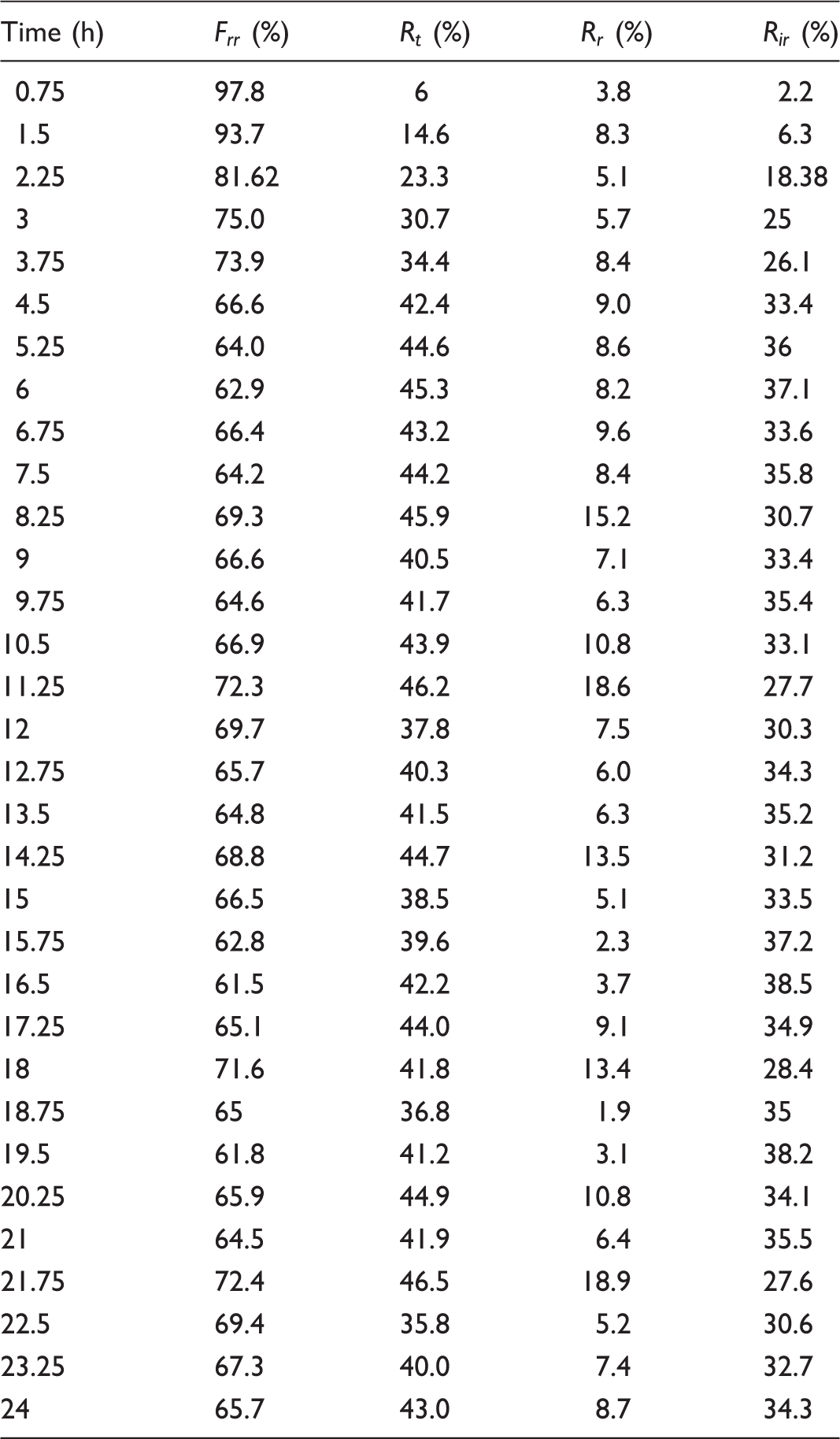
Subsequently, NF-20 was tested by multiple cycle filtration with 5 µm polystyrene microsphere dispersion to research its operational stability and antifouling properties. As shown in Figure 9, NF-20 possessed good durability, and its rejection efficiency remained at above 99% over the entire operation. The excellent durability of NF-20 was attributed to its structure and melt bonding. Given that membrane fouling is unavoidable during the experiment, the fouling property of membranes was investigated by measuring the membrane flux (Jn) and ( Membrane performance evaluation of multiple cycle filtration tests. (The cyan line is the flux of LPET nanofiber membrane. The red line is the flux of PA commercial membrane at 0.2 MPa. Both the LPET nanofiber membrane and PA commercial membrane have >99.9% rejection efficiency for polystyrene microspheres.)
Degree of antifouling of membrane.
Conclusions
Nanofibrous MF membranes with high flux, low pressure drop, and high retention capacity were obtained by pore filling of short-cut LPET nanofibers into PET nonwoven scaffold via wet-laid technology. The short LPET nanofibers are anchored on the surface of the PET fibers by heat treatment to form a crosslinked nanostructure mesh with very high porosity and a specific surface in the pores. The morphology, pore size distribution, zeta potential, contact angle, MF experiment, and mechanical properties were characterized. The results indicated that the filling of short nanofibers can effectively adjust the pore size and pore size distribution of the membranes. The membranes not only possessed good interception ability for 5, 3, and 1.3 µm polystyrene microspheres but also exhibited good water permeability performance. The water permeability performance is greater than that of LPET nanofiber membrane (196.1 L/m2 min, 0.1 MPa) and PA MF membrane (103.9 L/m2 min, 0.2 MPa). In the circulating filtration test, with the accumulation of membrane fouling in the filtration, the membrane is also effective in retaining particulate matter while improving the antipollution ability. Improved antipollution ability can effectively remove the pollutants on the membrane and restore the membrane flux. Thus, the membrane has good antipollution ability. The results confirm that the method of mixing short nanofibers with staple fibers can greatly improve the application performance of nanofibers. Moreover, solution blowing is a quasi-commercial method that can be employed to produce nanofibers. It has been proven as an effective method for the direct and continuous fabrication of nanofibers for industrial production.
Footnotes
Declaration of conflicting interests
The author(s) declared no potential conflicts of interest with respect to the research, authorship, and/or publication of this article.
Funding
The author(s) disclosed receipt of the following financial support for the research, authorship, and/or publication of this article: the National Key Technology R&D Program (2016YFB0303300), the National Natural Science Foundation of China (51473121 and 51403155), the Science and Technology Plans of Tianjin (15JCYBJC47200, 16PTSYJC00110, and 17JCYBJC17200) and the Tianjin Education Commission Research Project (2017KJ068).