
Abstract
Smart and interactive textiles have been attracted great attention in recent years. This research explored three different techniques and processes in developing textile-based conductive coils that are able to embed in a garment layer. Coils made through embroidery and screen printing have good dimensional stability, although the resistance of screen printed coil is too high due to the low conductivity of the print ink. Laser cut coil provided the best electrical conductivity; however, the disadvantage of this method is that it is very difficult to keep the completed coil to the predetermined shape and dimension. The tested results show that an electromagnetic field has been generated between the textile-based conductive coil and an external coil that is directly powered by electricity. The magnetic field and electric field worked simultaneously to complete the wireless charging process.
Keywords
Introduction
Wireless charging [1,2] means electrical energy is transferred over a short distance without any physical connection but electromagnetic field. Wireless charging technologies can be broadly classified into non-radiative coupling-based charging and radiative RF-based charging [3] as shown in Figure 1. The former consists of three techniques: inductive coupling [4], magnetic resonance coupling [5] and capacitive coupling [6], while the latter can be further sorted into directive RF power beamforming and nondirective RF power transfer [7].
Categories of wireless charging technologies. RF: radio frequency.
Wireless charging electronic devices are available in recent years due to its many advantages as compared to traditional cord charging. Wireless charging system works through transferring energy from a charger/emitter to a receiver via electromagnetic induction. The receiver converts an alternating electromagnetic field into electricity used to power electronic devices. In mobile device charging, tightly coupled inductive charging technology has been extensively adopted in recent years [8,9]. Such technology requires strong mutual coupling between a power transmitting unit and a power receiving unit in order to generate a high coupling coefficient.
Currently, the commercial available coils used as receiver for wireless charging system are made by winding one or two layers of the Litz wire. The coils are stiff and not suitable to be embedded in a garment for wirelessly charging a device worn next to skin for monitoring the physiological properties. With the development of wearable technology, it increases the need for charging wearable devices without physical contact where flexible electric receiver and textile-based coils are required from the wear comfort point of consideration. A wireless power transmission system will be ultimately integrated into textile substrates, so that the properties and feel of the fabric will not be compromised.
Conductive fibres/yarns and inks are essential part of the next generation of wearable electronics, enabling seamlessly integrated electronic function into textiles through various techniques and processes [10]. Seyedin et al. [11] fabricated a type of fabric using conductive and elastomeric fibres to be worn directly on various body parts for strain sensing. Conductive ink has been developed for printing conductive lines on a Tencel fabric [12]. Inductive textile-based coil has been developed by researchers for use in electrocardiogram monitoring [13] and wireless charging system [14]. For the use of wireless power transmission, the coil is ideally constructed by conductive material with low resistance such as copper, which can minimise the resistive loss in the coils. Conductive textile-based materials have relatively high resistance than conventional conductive metals; as a result, coils made of these types of materials have high resistance which may significantly affect the efficiency and operation of the wireless power transmission system [15]. It may explain the reason that the commercial available coils are made of copper wires. The research also reported that circular coils were found to transfer more energy for coil separations greater than 5 mm than square coils and using circular coils formed using sewing wire would give the best combined flexibility and electrical performance.
Till now, there is very few published research in wireless charging of wearable electronics. With the increased demand in wearables, wireless charging of wearable electronics for monitoring physiological properties for special population such as paralysis becomes desiderata. This research was aimed to develop a type of flexible textile-based coils to be used in a wireless charging system. The coil is made of textile materials with all the required flexible features and performs as the coil receiver that will be embedded in a garment. The fabrication techniques of the flexible coil will be explored and the constraints imposed by the processes on properties of the coil will be revealed.
Concept development of design textile-based soft coils
Design of flexible conductive coil has made reference to a commercial wireless charging coil WE-WPCC TRASM Qi-A5, which is a flat spiral coil with inner and outer diameters of 20 and 40 mm, respectively. Its inductance is 10 µH. To obtain a tightly coupling with the commercial coil, the soft textile coil is required to be the same as the commercial coil. The inner diameter of the textile-based coil was designed to be 20 mm, and the outer diameter will be determined by the diameter of the conductive windings, the number of turns and the space between any two adjacent turns.
According to Harold A. Wheeler's formula, the inductance (L in µH) of a one-layer flat spiral coil can be calculated approximately according to the inner diameter of the coil, the number of turns, the diameter of the wire and the space between turns as shown below

When the diameter of the wire ‘dw’ and the space between the adjacent two turns ‘s’ are specified, the required number of turns can be calculated according to the above Wheeler's equation.
Three technical approaches were explored when developing the textile-based coils, naming machine embroidery, laser cutting and screen printing. In each method the coils were designed with predetermined parameters of ‘n’, ‘dw’, ‘s’ and ‘Di’. Three different conductive materials including conductive thread, conductive fabric and conductive ink were applied individually to fabricate the textile-based coil. Comparing to the same counterpart conventional fabric, conductive fabrics and coils have reduced fabric drape and handle value due to the change of thickness, fabric weight, fibre/yarn interaction within the fabric, but they still have sufficient flexibility to be embedded in any wearable textiles.
Techniques for textile-based soft coils
Embroidered fabric coil
Embroidered coil was made of conductive sewing thread stitched on a plain woven fabric substrate through a computerised embroidery machine. There are different types of conductive threads commercially available; however, not all of them are suitable for machine embroidery, where high surface smoothness and strength are required. Conductive sewing thread Electro-Fashion from Kitronik was chosen due to its low electrical resistance, that is approximately 40 Ω/m. The thread with 0.5 mm in diameter is plated by silver and heavier than regular sewing threads. During the experiment, the conductive thread appeared frayed after a few stitches and was eventually broken. A thinner conductive thread (supplied by Adafruit) was also tested. It is a two-ply thread made of 100% stainless steel with a diameter of 0.2 mm with slightly higher resistance of 53 Ω/m. Testing result shows that due to the relative stiffness of the metal thread, the sewing needle of the embroidery machine was broken. A silver plated conductive polyamide thread from Shieldex was also tested and it was found suitable to be used on the embroidery machine. The thread is two ply and has yarn count of 117 dtex. However, the electrical resistance of the thread is 280 Ω/m, which is much higher than the above two types of conductive threads.
The embroidery machine used in this research is a computerised embroidery machine, Brother Super Galaxie 2100. The silver plated conductive thread was used as upper thread and a non-conductive polyester thread was used as lower thread for this study. The minimum space between the adjacent parallel stitches that can be achieved is 1 mm. According to Wheeler's formula, when the inner diameter of the coil is 20 mm, the diameter of the conductive thread is 0.17 mm and the space between any adjacent two turns is 1 mm. Sixteen turns of the windings will be required to achieve an approximate inductance of 10.47 µH of the coil. With these parameters, a coil design was first drawn by using Adobe Illustrator and then imported into the Brother PE-Design system which transfers the pattern into a compatible format recognisable by the embroidery machine. As shown in Figure 2(a), the coil pattern was embroidered on a black coloured plain woven polyester fabric using the embroidery machine. The choice of woven structure is based on the fact that a woven fabric substrate can maintain good dimensional stability of the coil compared to knitted fabric substrate. The embroidered fabric coil sample is shown in Figure 2(b).
(a) The embroidery machine and (b) an embroidered coil.
Laser cut fabric coil
A type of Ripstop conductive fabric supplied by Kitronik was selected for laser cutting. The fabric is a nylon woven fabric plated with silver, which makes it highly conductive. Its surface resistance is less than 1 Ω/square. Conductive fabric coils were cut using a programmed laser cutting machine FB Series.
Several coil patterns with different thickness of windings were designed and drawn in Adobe Illustrator. As shown in Figure 3, the pattern only contains the outline of the coil required by the laser cutter programme. The designed pattern was imported to ApS-Ethos software for preparation and the cutting process was conducted on the Laser Cutter. The cut coils are shown in Figure 4.
A designed coil pattern for laser cutting. Patterned conductive coils were cut by a laser cutter.

Experimental work showed that the conductive fabric is too thin and flexible to hold the fabric in place causing problem in accurately cutting the coils into predetermined pattern. To solve the problem, a cotton woven fabric was attached to the back side of the conductive fabric by an adhesive media Bondaweb. The fabric bonding process was conducted on a heat press machine at 180℃ for 3 s. During the cutting process, optimum machine settings for cutting coil pattern from the combined fabric were obtained, using two passes of cutting.
Another finding from laser cutting method is that when the diameter of the windings of the coil is less than 1 mm, the patterned coil was rather brittle when being taken off from the backing fabric. Therefore, in order to obtain a continuous (connected) patterned coil, the diameter of the windings was set at 1 mm, which was also set as the space between any two adjacent turns. According to Wheeler's formula, when the inner diameter of the coil is 20 mm, the diameter of the conductive windings is 1 mm and the space between adjacent turns is 1 mm, 14 turns in total of the windings of the coil will generate an inductance of 8.89 µH, approximately. A sample of laser cut coil is shown in Figure 5, which was temporarily taped on a fabric for further measurement. Although the laser cut coil can be sewn onto a fabric, it can be very difficult to retain the coil and each turn in its predetermined space of adjacent turns and the dimensional accuracy. Further research is needed to resolve this problem.
A sample of the laser cut coil.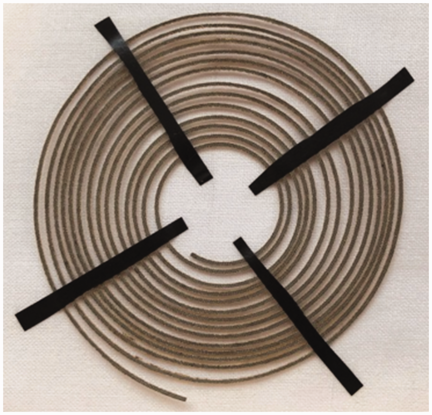
Screen printed fabric coil
Screen printed coil was made through printing a type of conductive ink onto a fabric substrate. There are different types of conductive inks, pigment and paste with different conductive materials such as copper, carbon and silver suitable for applying onto a fabric substrate. However, not all of them can be applied through conventional textile screen printing process. For example, nano-copper-based conductive paste from GWENT needs to be sintered in a formic acid oven after being screen printed on a fabric surface. In this research, a conductive pigment was chosen to be applied onto a plain woven fabric through conventional textile screen printing technique. The printing ink is a water-based carbon pigment from Bare Conductive in London.
The coil pattern designed and developed in Adobe Illustrator in ‘Laser cut fabric coil’ section was transferred onto a conventional textile printing screen through a photochemical process. A semi-automatic printer was used to print the designed coil pattern onto a woven fabric as shown in Figure 6(a). To obtain a proper printed coil pattern, medium sized printing roller and the medium printing pressure (level 3 of the machine) were used.
(a) Coil printing set-up and (b) a sample of screen printed coil.
It was found that an achievable diameter of the printed circles and space between any two adjacent circles on a printed coil is 0.6 mm. According to Wheeler's formula, when the inner diameter of the coil is 20 mm, the diameter of the conductive windings is 0.6 mm and space between any two adjacent turns is 0.6 mm, it will generate an inductance of approximately 10.52 µH with a total circle of 16 in the coil. A sample coil printed using one pass on the printing machine is shown in Figure 6(b).
Electrical performance of the developed textile-based coils
Electrical properties of soft coils
The electrical inductance and resistance, and quality factor of the developed textile-based coils were measured using HM8118 LCR bridge as shown in Figure 7.
Measurement of the inductance, resistance and quality factor of the developed textile-based coils: (a) HM8118 LCR bridge, (b) measurement of embroidered coil, (c) measurement of laser cut coil and (d) measurement of printed coil.
Electrical properties of the textile-based coils.
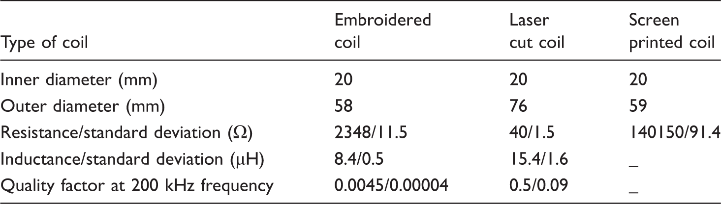
The high resistance is a significant drawback of textile-based coils, which directly diminishes the quality factor of the coil, and will affect the energy transfer efficiency. Due to the difference between the conventional materials used for inductive coils such as copper and conductive textile-based materials, the Wheeler's formula might be inappropriate to estimate the inductance of textile-based coil. In order to reduce the resistance of the textile-based conductive coil, the diameter of the circles needs to be enlarged. For instance, the resistance of the embroidered coil could be reduced from 2348 to 866 Ω by stitching the coil pattern twice at a time as shown in Figure 8. This method will retain the outer diameter of the coil. For the laser cut coil, a few layers of conductive fabric could be bonded together before undergoing laser cutting process, so as to increase the thickness of the conductive windings, ultimately reducing the resistance of the coil. Similar concept could be applied to screen printing of conductive textile coils. Applying more printing layers on the coil pattern will increase the thickness of the windings within the coil, hence reduce the resistance of the conductive textile coil.
Embroidered coil stitched using two threads at a time to reduce the resistance. DC: direct current.
Wireless power transmission test using a soft coil
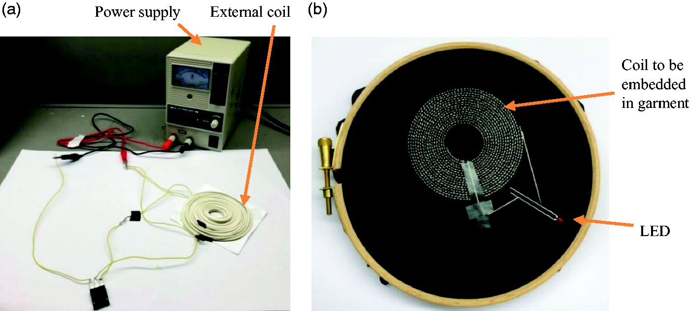
The embroidered coil shown in Figure 8 was tested on a wireless power transmission system, which includes a power transmitter and a power receiver. The transmitter consists of a power source, two inductive coils (L1 and L2) made of twin coded speaker cable with 14 turns, a resistance with 220 Ω and a transistor T1P35C. The power receiver is the sample of embroidered coil connected with a LED to its ends. The schematic diagram of the wireless power transmission system is illustrated in Figure 9, and the images of the physical circuits are shown in Figure 10.
Schematic diagram of the wireless power transmission system. The physical circuit of the wireless power transmission system: (a) power transmitter and (b) textile-based power receiver. LED: light-emitting diode.
The power transmission from the transmitter to the textile-based receiver was achieved by a changing magnetic field. First, a direct current (DC) was provided by a DC power supply (plugged directly into the wall outlet) at around 4.6 V, shown in Figure 11. The DC was converted into high frequency alternating current in the transmitter circuit. The alternating current energises the transmitter coil and generates an oscillating magnetic field. Second, when the receiver coil was placed near to the transmitter coil, the oscillating magnetic field induces an electric current in the receiver circuit and lights up the LED as shown in Figure 11. The test demonstrated that the electrical energy was successfully transferred from the transmitter base to the textile-based receiver wirelessly, without any physical contact.
Wireless power transmission test of a two layer embroidered coil that charged a LED. DC: direct current; LED: light-emitting diode.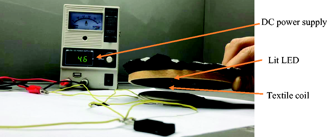
This is a collaborative research work between Heriot-Watt University and FtW Feel the Warmth CIC which produces high performance heated wearables therapeutic properties as well as keeping the wearer warm. The novelty of the research work is that it demonstrated the possibility of incorporating textile-based flexible conductive coil into the high performance heated textiles for wirelessly charging the battery in the wearables for disabled people. Some of the important aftercare properties of the coil will be further investigated.
Conclusions
Techniques of engineering design flexible textile-based coils for wireless charging wearable electronics have been investigated in this study.
Three different techniques for fabrication of textile-based coils have been explored, including embroidery, laser cutting and screen printing. Textile-based coils were fabricated with predetermined parameters through the three approaches. Different conductive materials were tried under each method. Constraints were found on the dimension of the coils, imposed by the fabrication process of each method. They have direct influence on the resistance of the coil, hence the performance of the coil. Although the laser cut coil has relatively lower resistance, it has difficulty in holding the whole coil in a predetermined dimension. On the other hand, the screen printed coil has very high resistance. The embroidered coil has demonstrated a workable solution to be incorporated in a garment for wireless charging. It has demonstrated the ability of successful wireless charging wearable electronic device. This implies that the developed textile-based coil could be embedded in wearable clothing, receiving electric power wirelessly. This created a way of charging wearable sensors for applications such as health monitoring, protection, etc.
Footnotes
Declaration of conflicting interests
The author(s) declared no potential conflicts of interest with respect to the research, authorship, and/or publication of this article.
Funding
The author(s) disclosed receipt of the following financial support for the research, authorship, and/or publication of this article: The research described in this paper was financially supported by the Scottish Funding Council.