
Abstract
The influence of spinning temperature on ultrahigh-molecular-weight polyethylene/high-density polyethylene as-spun blend filaments and the influence of drawing temperature on ultrahigh-molecular-weight polyethylene/high-density polyethylene-blend fibers were investigated. The results showed that the optimum spinning and hot-drawing temperatures were 310℃ and 85℃, respectively, and blending with high-density polyethylene improved the orienting ability of the molecular chains and the crystallization ability. The blend filaments spun at 310℃ had the best molecular chain orientation, crystallinity and crystal orientation of the filaments examined; both lower and higher spinning temperatures were detrimental to the crystal structure growth of the as-spun blend filaments. The optimum drawing temperature of the blend fibers was 85℃, which resulted in blend fibers with the best molecular chain orientation, crystallization, and crystal orientation as well as the thinnest grains of the fibers examined. The highest tensile strength and initial modulus were 1204 MPa and 20.4 GPa, respectively; these high values can be attributed to the fibrillar structure, which consisted of extended molecular chains and thin grains. The results in this paper can help disclose the effect mechanism of formation temperature on the melt spinning method used to produce high-strength ultrahigh-molecular-weight polyethylene fibers.
Keywords
Introduction
Due to the excellent characteristics of ultrahigh-molecular-weight polyethylene (UHMWPE) fibers, including high specific strength, high chemical resistance and low density, UHMWPE fibers have attracted great attention. At present, the gel spinning method is used in industry for the production of high-strength and high-modulus UHMWPE fibers. However, this method is associated with various problems, such as environmental pollution, high costs and low production efficiency [1]. The above problems of the gel spinning method are solved by using the melt spinning method; thus, melt spinning is the main industrial method for producing polyester (PET) [2–5], polypropylene (PP) [6–8] and other fibers. However, due to their extremely high viscosity after melting, UHMWPE materials must be modified to meet the processing requirements of the melt spinning process [9]. Blending UHMWPE with low-molecular-weight polymers can modify the flowability of UHMWPE, even under gel processing conditions. Adding low-density PE (LDPE) [10], linear low-density PE (LLDPE) [11], isotactic polypropylene (iPP) [12] or polysilane [13] can reduce the viscosity of blend gels. In melt processing methods, conventional PE is a widely used additive to improve the processability of UHMWPE. The viscosity of melts of UHMWPE blends with medium-density PE (MDPE) [14] and LLDPE [11] is significantly lower than that of pure UHMWPE. Researchers have tried to prepare UHMWPE and conventional PE blend fibers using the melt spinning method, and melts of UHMWPE blended with LDPE [15], LLDPE [16] or polyolefin [17] have been spun successfully. In this study, we produced a blended material using high-density PE (HDPE).
Because of the highly oriented and fully extended chains in highly crystalline structures, UHMWPE gel fibers have superior mechanical properties [18,19]. Peterlin [20] proposed a model for drawn PE, which can describe the structural and morphological development of PE fibers at various drawing ratios. Hoogsteen et al. [21] found that the as-spun filaments originally contained lamellar or shish-kebab structures. Those structures could be incompletely transformed into fibrillar structures using low hot-draw ratios and completely transformed using high hot-draw ratios. Ohta et al. [22] found that the shish-kebabs developed in both as-spun and drawn fibers can be transformed continuously into the microfibril structure composed mostly of the shish-kebab structure through the hot-drawing process. The results suggested that the chains in the kebab structures are incorporated into the shish structures and consumed to extend the longitudinal dimension of the shish structures during the drawing process. Litvinov et al. [23] suggested that the fiber morphology can be described as a mixture of crystalline fibrils and large chain-extended crystals. They found that, at the final stage of the production of the UHMWPE fibers, the crystallinity, the orientation of crystals and the average crystal size in the direction perpendicular to the fiber axis increased, while the long period of fibrils and the break load of fibers decreased. Murase et al. [24] proposed a kinetic pathway leading to shish-kebab formation and various transient structures evolved therein. They elucidated an important role of the flow-induced phase separation in the flow-induced shish-kebab formation. An et al. [25] investigated the cold drawing process of UHMWPE fibers. They found that, with the increase in the cold drawing ratios, better folded chains and amorphous chains were involved in the formation of shorter and better-oriented shish structures. Xu et al. [26] found that the original lamellae structure that formed in the early stage was destructed to form the shish structure, and the new shish structure had a shorter shish length than the original shish structure. The formation temperatures, including spinning temperature and drawing temperature, are major factors that affect the microstructure and mechanical properties of UHMWPE fibers. Jian et al. [27] suggested that as-spun fibers obtained by spinning at an optimum temperature had the best microstructure suitable for ultradrawing. Smith and Lemstra [28] found that the maximum draw ratio for gel fibers gradually increased with increasing drawing temperature. Yeh et al. [29] suggested that good orientation of UHMWPE molecules along the drawing direction benefits the tensile strengths and moduli of fiber specimens obtained by drawing the fiber specimens at a high temperature. Cao et al. [30] proposed two distinct evolution models at stretching temperatures of 25℃ and 100℃. They found that stretching-induced crystal melting occurred at 100℃ but did not occur at 25℃.
In the melt spinning and subsequent hot-drawing process, the surface quality and crystal structure of the fibers determine the characteristics of the as-spun filaments, which are significantly affected by spinning temperature. Although the crystal structures of the UHMWPE [31,32] fiber and UHMWPE/HDPE-blend fiber [33] prepared by melt spinning have been studied, the effect of formation temperature on the crystal structure and mechanical properties of the UHMWPE/HDPE-blend fibers has not been reported. In this paper, the crystal shapes of UHMWPE/HDPE as-spun blend filaments and fibers formed at various formation temperatures were studied, and the effect of HDPE on the crystal structure of the as-spun blend filaments and fibers prepared at various formation temperatures was analyzed. Investigations including the sound velocity orientation test, the wide-angle X-ray diffraction (WAXD) test, and thermal and tensile experiments were performed on the fiber specimens to further investigate the influence mechanism of formation temperature on the crystal structure and mechanical properties of the fibers.
Experimental method
Materials
UHMWPE resin (GUR4012, Celanese Corporation, Nanjing, China) with a weight-average molecular weight (Mw) of 1.5 × 10⁶ and HDPE (5000S, Yanshan Petrochemical Company, Beijing, China) with an MFI of 0.9 g/10 min were used in this study.
Preparation of UHMWPE/HDPE-blend fibers
The devices used in the spinning and hot-drawing process and the related process parameters were the same as those in a paper we previously published [33]. Blends of UHMWPE and HDPE are referred to as U/H, and neat UHMWPE is referred to as U. In this study, the initial and hot-drawing ratios were fixed at 9 and 15, respectively, and seven spinning temperatures, i.e. 270℃, 280℃, 290℃, 300℃, 310℃, 320℃ and 325℃, were set at the spinneret to produce the as-spun filaments. The obtained as-spun filaments spun at 310℃ were later hot drawn using a custom stretching machine at 60℃, 70℃, 75℃, 80℃, 85℃, 90℃ and 95℃, respectively. A flowchart of the sample preparation process is shown in Figure 1.
Flowchart of the sample preparation process.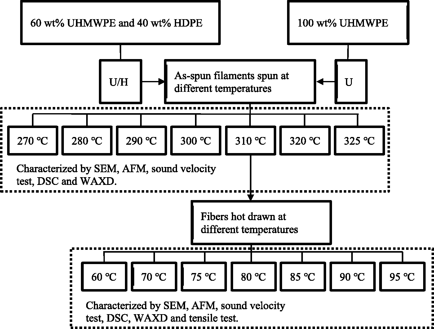
Analytical methods
Differential scanning calorimetry (DSC2, Mettler Toledo, Greifensee, Switzerland) was used to determine crystallinity. The weight of a typical sample was ∼ 5 mg. The samples were heated from 25℃ to 250℃ at a rate of 10℃/min in a nitrogen atmosphere. The crystallinity of the samples was determined using equation (1):

WAXD experiments of the (110), (200) and (020) planes were carried out using an X-ray diffractometer (Bruker AXS D8 Advance diffractometer, Bruker, Billerica, MA, USA, Cu Kα radiation, λKαl = 1.542 Å, scanned from 5° to 50° by 2θ at a scanning speed of 10°/min); the WAXD experiments of the (002) plane were carried out using an X-ray diffractometer (XRD, EMPYREAN, PANalytical Co., Almelo, Netherlands, Cu Kα radiation, scanned from 70° to 78° by 2θ at a scanning speed of 0.013°/step). Azimuth angle scanning was carried out in the range from −90° to 90° at 0.1°/min, and 2θ was fixed on the scanning curve maxima (21.4°). Two theta angles were calibrated according to the diffraction positions of standard Si powder. The grain size (Lhkl) of the planes was calculated using the Scherrer equation (equation (2)):


The sound velocity of the samples was measured using an SSY-III sound velocity orientation instrument (Donghua University, Shanghai, China). The sound velocity orientation factor of the samples was calculated using equation (5):
Single-fiber tensile testing was performed using an YG001A-1 electronic fiber-strength tester (Hongda Fangyuan Electric Co., Ltd., Taicang, China) at an extension rate of 20 mm/min. The length of the fiber sample was set to 20 mm. At least five tests were averaged for each sample.
A SMART biological microscope was used to measure the fiber diameter.
The surface roughness and morphologies of the as-spun filaments and fibers were characterized by a DMFASTSCAN2-SYS atomic force microscopy (AFM, Bruker, Santa Barbara, CA). AFM images of the as-spun filament samples were obtained with a scan area of 5 × 5 µm2. The surface roughness of the samples was calculated with equations (6) and (7) using the instrument software:


Results and discussion
SEM and AFM studies
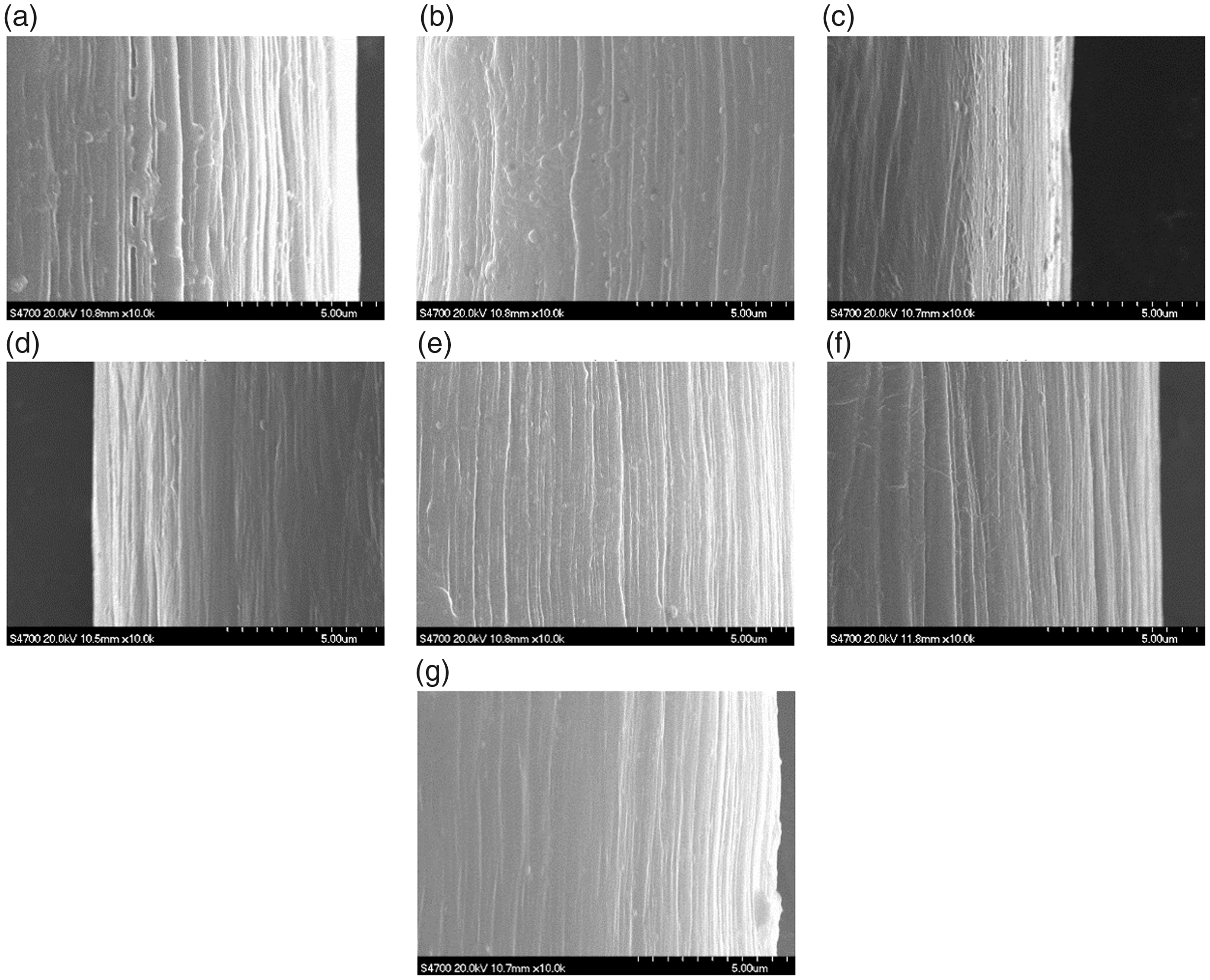
The images in Figures 2 and 3 show the surface morphology of the U/H and U as-spun filaments, respectively. As shown in Figures 2 and 3, the surface of both U/H and U as-spun filaments became smoother as the spinning temperature increased. Ra and Rq of the as-spun filaments are shown in Figure 4. Ra and Rq of both U/H and U as-spun filaments decreased with increasing spinning temperature. Ra and Rq of U/H as-spun blend filaments decreased rapidly from 290℃, and those of U as-spun filaments decreased rapidly from 300℃. The relationship between Ra and Rq with spinning temperature was analyzed by third-order polynomial fitting, and the regression equations are listed in Table 1. As the critical extension rate increased with increasing melt temperature [36], with a fixed extruding speed and initial drawing speed, the melt fracture phenomenon disappeared on the surface of as-spun filaments spun at higher temperatures. Therefore, the as-spun filaments exhibited better processability at higher spinning temperatures. The surface of U/H as-spun filaments is smoother than that of U as-spun filaments (Figures 2 and 3), and Ra and Rq of U/H as-spun blend filaments were lower than those of U as-spun filaments (Figure 4) processed at the same spinning temperature, indicating that blending with HDPE can improve the processability of UHMWPE/HDPE blends during the melt spinning process.
SEM images of U/H as-spun filaments prepared at several spinning temperatures: (a) 270℃; (b) 280℃; (c) 290℃; (d) 300℃; (e) 310℃; (f) 320℃; (g) 325℃. SEM images of U as-spun filaments prepared at several spinning temperatures: (a) 270℃; (b) 280℃; (c) 290℃; (d) 300℃; (e) 310℃; (f) 320℃; (g) 325℃. Surface roughness of as-spun filaments: (a) Ra; (b) Rq (▪: U/H as-spun blend filaments; •: U as-spun filaments). Regression equation for Ra and Rq to spinning temperatures.


Figures 5 and 6 present the surface morphologies of U/H and U fibers, respectively. As shown in Figures 5 and 6, the fibers all had texture along the axis direction. The texture became slightly shallower as the drawing temperature increased, and the surface quality of U/H fibers was slightly better than that of U fibers processed at the same hot-drawing temperatures. Ra and Rq of the fibers are shown in Figure 7. The results of AFM in Figure 7, i.e. Ra and Rq decreased slightly with increasing hot-drawing temperature in a small range of decrease, are basically in accordance with the SEM images in Figures 5 and 6. Ra and Rq of the U/H blend fibers are lower than those of the U fibers processed at the same drawing temperature. We believe that adding HPDE can increase the heat sensitivity of the surface on the U/H fibers, and thus, the values of Ra and Rq for the U/H blend fibers decreased with increasing drawing temperature. However, the heat sensitivity of U fibers that were not blended with HDPE was not improved; thus, the decreases in the Ra and Rq of U fibers with an increase in hot-drawing temperature were less obvious than those of U/H fibers.
SEM images of U/H fibers drawn at several temperatures: (a) 60℃; (b) 70℃; (c) 75℃; (d) 80℃; (e) 85℃; (f) 90℃; (g) 95℃. SEM images of U fibers drawn at several temperatures: (a) 60℃; (b) 70℃; (c) 75℃; (d) 80℃; (e) 85℃; (f) 90℃; (g) 95℃. Surface roughness of fibers: (a) Ra; (b) Rq (▪: U/H as-spun blend filaments; •: U as-spun filaments).

Sound velocity orientation studies
Sound velocity is independent of crystallinity. Therefore, the orientation factor calculated from the sound velocity was used as a measure of the average orientation of all molecular chains in the sample regardless of the degree of crystallinity [37]. The sound velocity orientation factor (fs) of the as-spun filaments is shown in Figure 8. As seen in Figure 8, the fs value of U/H was 29.85, which was 18.31% higher than that of U as-spun filaments, when the spinning temperature was 270℃. The fs value of U/H as-spun blend filaments increased to a maximum value as the spinning temperature increased to 310℃, and the maximum fs value of U/H as-spun blend filaments was 41.65, which is 39.53% higher than that of U/H as-spun blend filaments spun at 270℃ and 36.29% higher than the maximum fs value of U as-spun filaments, which was obtained at 320℃. When the spinning temperature increased to 325℃, the fs value of U/H as-spun blend filaments decreased to 38.42, which is 28.62% higher than that of U as-spun filaments. The motion units in the as-spun filament melt are whole molecular chains, and the thermal movement of the molecular chains was more active at higher temperatures. The interaction forces between the molecular chains were weakened, and the disentanglement speed was quickened, resulting in the decrease in the melt elongation viscosity [38]. Therefore, the fs value of both the U/H and U as-spun filaments increased with the increase in spinning temperature. As a fluidity modifier, HDPE can help the UHMWPE molecular chains slip past each other and reorient [39], and HDPE can help disentangle UHMWPE molecular chains during melt processing [40,41]. Therefore, the spinning temperature at which the U/H as-spun blend filaments had the highest fs value was lower than that of the U as-spun filaments and close to the rapid degradation temperature when the spinning temperature exceeded 320℃, resulting in the breaking of molecular chains under the initial drawing force and the inhibition of the interaction between extremely long molecular chains of UHMWPE and relatively short chains of HDPE. Therefore, fs of the U/H as-spun blend filaments began to decrease when the spinning temperature increased from 310℃ to 320℃ and decreased rapidly at temperatures exceeding 320℃.
Results of the sound velocity orientation tests of as-spun filaments prepared at various spinning temperatures (▪: U/H as-spun blend filaments; •: U as-spun filaments).
The results of the sound velocity orientation tests of fibers drawn at various temperatures are presented in Figure 9. As shown in Figure 9, the fs value of the U/H blend fibers increased rapidly as the drawing temperature increased from 70℃ to 75℃, and the highest fs value (96.85) was obtained at 85℃. A rapid increase in the fs value of the U fibers occurred when the drawing temperature increased from 75℃ to 80℃. The highest fs value of the U fibers was 96.22, which was obtained at 90℃. The fibers are in a highly elastic state during the hot drawing process, and the motion units are chain segments. With increasing drawing temperature, the movability of the chain segments was enhanced, and the force needed for molecular chain orientation decreases [42]. Therefore, the chain segments could be stretched along the drawing direction when the fibers were drawn at a temperature below the melting point. Due to the disentanglement effect of the HDPE molecule, the chain segments of the U/H blend fibers are easily stretched; thus, the optimum temperature of U/H blend fibers was lower than that of U fibers. When the hot-drawing temperature was higher than 90℃, the fs value of the U/H blend fibers decreased rapidly, and the fs value of the U fibers decreased slightly. A drop in the fs values at temperatures higher than 90℃ occurred because a small number of molecular chains began to slip as the drawing temperature exceeded 90℃.
Results of the sound velocity orientation tests of fibers drawn at various temperatures (▪: U/H blend fibers; •: U fibers).
DSC analyses
Figure 10 presents the crystallinity of as-spun filaments prepared at various spinning temperatures. As shown in Figure 10, the crystallinity of the U/H as-spun blend filaments increased rapidly as the spinning temperature increased from 280℃ to 290℃. The highest crystallinity of the U/H as-spun blend filaments was 58.01%, which was obtained at 310℃. The crystallinity of the U fibers increased rapidly as the spinning temperature increased from 290℃ to 310℃. The highest crystallinity of the U as-spun filaments was 54.58%, which was obtained at 310℃. As melt orientation prior to crystallization increases, the entropy of the sample decreased due to the better alignment of the molecular chains. The energy barrier decreased as the molecular chains oriented in the drawing direction, resulting in an increase in the degree of crystallinity [43]. The results of the sound velocity orientation test (as shown in Figure 8) indicated that the degree of the molecular chain orientation of the as-spun filaments increased as spinning temperature increased and then remained at a relatively high level at 310℃ for U/H as-spun blend filaments and at 320℃ for U as-spun filaments. Therefore, crystallinity increased with increasing spinning temperature. When the spinning temperature exceeded 310℃, the crystallization decreased with decreasing molecular chain orientation. The crystallinity of U/H as-spun blend filaments was higher than that of U as-spun filaments processed at the same spinning temperatures, and the difference increased as the spinning temperature increased from 280℃ to 310℃, indicating that the crystallization capacity of U/H as-spun blend filaments was improved by blending with HDPE due to the higher degree of the molecular chain of U/H as-spun filaments.
Crystallinity of as-spun filaments prepared at various spinning temperatures (▪: U/H as-spun blend filaments; •: U as-spun filaments).
The crystallinities of blend fibers hot drawn at various temperatures are shown in Figure 11. As seen in Figure 11, the crystallinity of the U/H and U fibers increased rapidly as the hot-drawing temperature increased from 70℃ to 75℃ and from 75℃ to 80℃, respectively. The U/H blend fibers exhibited the highest crystallinity (64.32%) at 85℃, and the U fibers exhibited the highest crystallinity (63.21%) at 90℃. During the hot-drawing process, the initial lamellar structure transformed into a fibrillar structure. This transformation induced better perfection of the crystalline regions and a higher degree of crystallinity. The elevated drawing temperatures enabled short time relaxations and lamellae thickening during fibrillation [44]. The stretchability of the molecular chains of the U/H blend fibers was improved through blending with HDPE, and these extended molecular chains formed more crystal regions. Therefore, the crystallinity of both the U/H and U fibers increased as the hot-drawing temperature increased, and the crystallinity of the U/H blend fibers was higher than that of the U fibers. However, when the drawing temperature exceeded the optimum drawing temperature, which is 85℃ for U/H blend fibers and 90℃ for U fibers, a few crystalline regions of the as-spun filaments began to gradually melt, and increasing numbers of crystalline regions became strain-induced molten regions as the drawing temperature increased [30]. Moreover, as shown in Figure 9, the molecular chain orientation degree of fibers drawn at higher temperatures began to decrease, which also resulted in a reduction in the crystallinity of the fibers.
Crystallinity of fibers drawn at various temperatures (▪: U/H as-spun blend filaments; •: U as-spun filaments).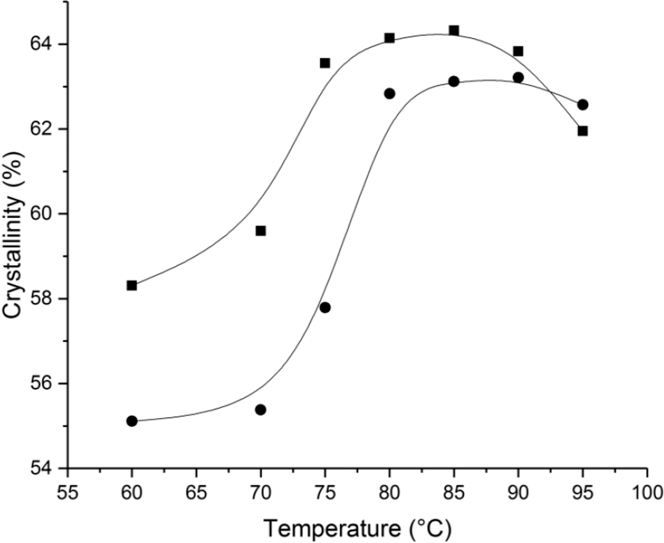
XRD data analysis
Orthorhombic crystal phases were the main crystalline phases in the UHMWPE fiber specimens [45], and there were four diffraction peaks in the spectrum of the orthorhombic crystal structure of PE that were of special interest: the (110), (200), (020) and (002) planes [46]. A schematic diagram of the (110), (200), (020), and (002) planes is shown in Figure 12. The (200) and (110) diffraction peaks appear at 2θ angles from 13 to 27°, the (020) diffraction peak appears at 2θ angles from 33 to 38°, and the (002) diffraction peak appears in the range from 72 to 76° [47]. The sizes along the normal direction of the four orthorhombic crystal planes (L110, L200, L020 and L002) were calculated using the Scherrer equation.
Plane orientation inside the orthorhombic unit cell: (a) (110) plane; (b) (200) plane; (c) (020) plane; and (d) (002) plane.
The grain sizes in the normal direction of the (110), (200), (020) and (002) planes of the as-spun filaments prepared at various spinning temperatures are presented in Figure 13. As shown in Figure 13, with increasing spinning temperature, L110, L200 and L020 of both the U/H and U as-spun filaments decreased. L002 of the U/H as-spun blend filaments first increased as the spinning temperature increased and then decreased after the spinning temperature exceeded 310℃. The data indicate that, as the spinning temperature increased from 270℃ to 310℃, the grain size in the radial direction (the normal direction of the (200) and (020) planes) decreased and that in the axial direction (the normal direction of the (002) plane) increased, but the grains of the filaments still had a longer dimension in the radial direction and a shorter dimension in the axial direction. As shown in Figure 13, the grain sizes in the radial direction of the U as-spun filaments were slightly higher than those of the U/H as-spun blend filaments, and the grain size in the axial direction of the U as-spun filaments was slightly lower than that of U/H as-spun filaments processed at the same spinning temperatures, indicating that blending with HDPE can form a slightly thinner grain shape in U/H as-spun blend filaments.
Crystal size of as-spun filaments prepared at various spinning temperatures: (a) L110; (b) L200; (c) L020; and (d) L002 (▪: U/H as-spun blend filaments; •: U as-spun filaments).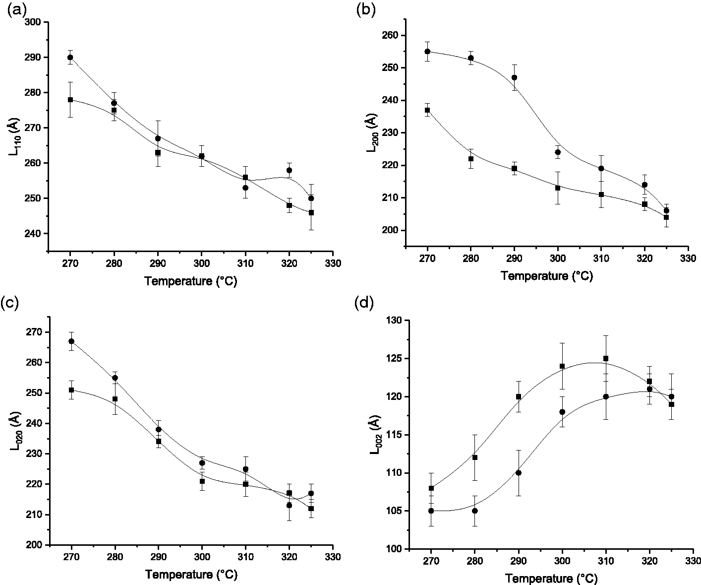
Figure 14 shows the crystal orientation degree of as-spun filaments spun at various temperatures. As shown in Figure 14, the fc values of both U/H and U as-spun filaments increased as the spinning temperature increased. With the same spinning temperatures, the fc values of the U/H as-spun filaments were higher than those of the U as-spun filaments, and the differences became larger as the spinning temperature increased from 270℃ to 310℃. Crystal orientation is affected by the molecular chain orientation and the grain shape of the as-spun filaments. As-spun filaments with higher fs values and thinner grains had higher fc values. The fs of U/H as-spun blend filaments increased and the grain shape of U/H as-spun blend filaments thinned as the spinning temperature increased from 270℃ to 310℃, and U/H as-spun blend filaments had a higher fs value and a thinner grain shape than U as-spun filaments processed at the same spinning temperatures. Therefore, the fc values of U/H as-spun blend filaments increased as spinning temperature increased from 270℃ to 310℃, and the fc values of U/H as-spun blend filaments were higher than those of U as-spun filaments processed at the same spinning temperatures. The molecular chain orientation degree, crystallinity and L002 of U/H as-spun blend filaments decreased when spinning temperature exceeded 310℃; thus, the fc value of U/H as-spun blend filaments slightly decreased when spinning temperature exceeded 310℃.
Crystal orientation of as-spun filaments prepared at various spinning temperatures (▪: U/H as-spun blend filaments; •: U as-spun filaments).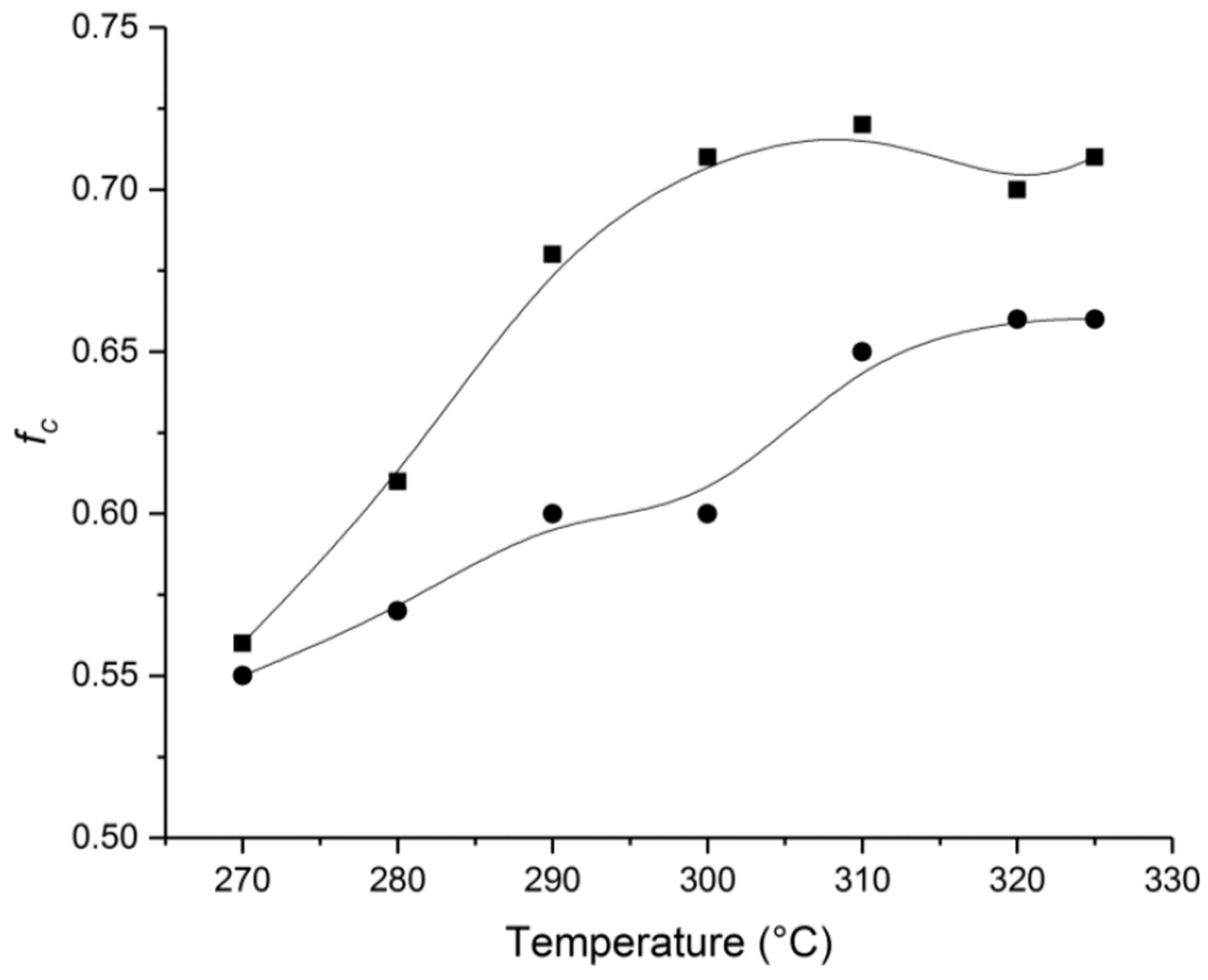
The L110, L200, L020, and L002 values of fibers hot drawn at various temperatures are presented in Figure 15. After combining the grain size data of the as-spun filaments in Figure 13, it can be found that L110, L200 and L020 decreased and L002 significantly increased during the hot-drawing process, suggesting that the grains were stretched in the axial direction and compressed in the radial direction. Therefore, the grains were stretched thin as the as-spun filaments were stretched to form fibers (as shown in Figure 16). In addition, the grain size of the fibers was affected by hot-drawing temperature. As shown in Figure 15, L110, L200 and L020 of both the U/H and U fiber samples decreased as drawing temperature increased and then increased as drawing temperature increased. The U/H blend fibers had the lowest L110, L200 and L020 values (134 Å, 102 Å and 102 Å, respectively) and the highest L002 value (393 Å) at 85℃. The U fibers had the lowest L110, L200 and L020 values (145 Å, 120 Å and 103 Å, respectively) and the highest L002 value (377 Å) at 90℃. The data in Figure 15 indicate that the U/H blend fibers and the U fibers had the thinnest grain shape at hot-drawing temperatures of 85℃ and 90℃, respectively, and the grains of the U/H blend fibers were thinner than those of the U fibers. It is likely that, because the molecular chains cannot be fully activated and the crystal grains are hard to fully stretch at a lower drawing temperature during the crystal structure reorganization process, the grains of the fibers drawn at lower temperatures had a higher dimension in the radial direction and a lower dimension in the axial direction than those of the fibers drawn at the optimum temperatures. As discussed above, molecular chain orientation along the axial direction can be improved through blending with HDPE, resulting in grains that are apt to grow along the axial direction; thus, the grains of U/H fibers are thinner than those of U fibers. Since the molecular chains slightly slipped and crystal structure strain-induced melting occurred when the fibers were drawn at higher temperatures, the fibers cannot attain the thinnest grain shape at temperatures higher than the optimum hot-drawing temperatures.
Crystal size of fibers drawn at various hot-drawing temperatures: (a) L110; (b) L200; (c) L020; and (d) L002 (▪: U/H blend fibers; •: U fibers). Schematic of the grains: (a) as-spun filaments and (b) fibers.
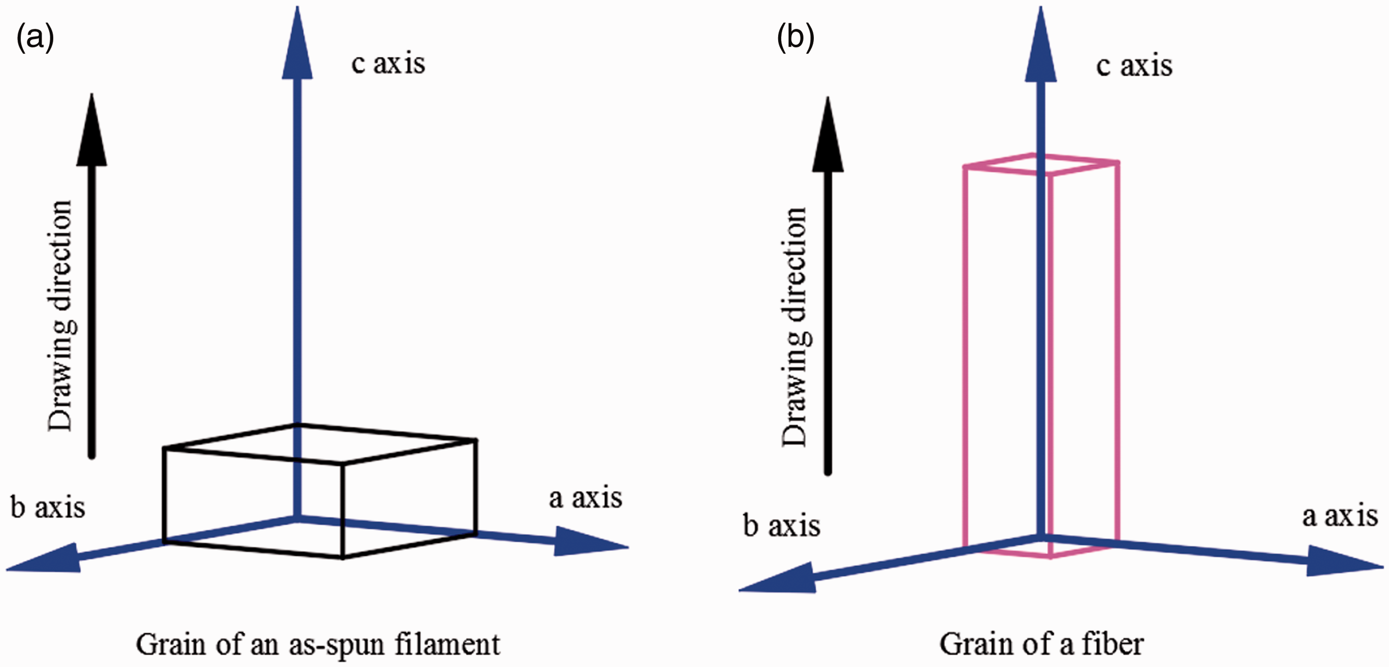
Figure 17 presents the fc values of fibers drawn at various hot-drawing temperatures. The fc values of U/H blend fibers increased rapidly as drawing temperature increased from 70℃ to 80℃ and reached a maximum (0.98) at 85℃. The fc values of U fibers increased rapidly as drawing temperature increased from 75℃ to 80℃ and reached a maximum of 0.96 at 90℃. The results in Figures 9 and 16 show that the U/H blend fibers and the U fibers had the highest fs value and the thinnest grain shape at 85℃ and 90℃, respectively. Since thinner grains are easily aligned in the drawing temperature and compacted in the radial direction, U/H blend fibers and U fibers attained the highest fc value at 85℃ and 90℃, respectively.
Crystal orientation of fibers drawn at various hot-drawing temperatures (▪: U/H as-spun blend filaments; •: U as-spun filaments).
Tensile tests
The diameters of as-spun filaments spun at various temperatures are shown in Table 2, and the diameters of fibers hot drawn at various temperatures are shown in Table 3. Figure 18 shows the tensile strengths and initial moduli of blend fibers drawn at various temperatures. As seen in Figure 18, the tensile strength and initial modulus of U/H blend fibers increased rapidly as the drawing temperature increased from 70℃ to 75℃, and U/H blend fibers had the highest tensile strength and initial modulus (1204 MPa and 20.7 GPa, respectively) at 85℃. The tensile strength and the initial modulus of U fibers increased rapidly as drawing temperature increased from 75℃ to 80℃, and the U fibers had the highest tensile strength and initial modulus (879 MPa and 19.5 GPa, respectively) at 90℃.
The mechanical properties of fibers drawn at various temperatures: (a) tensile strength and (b) initial modulus (▪: U/H as-spun blend filaments; •: U as-spun filaments). Diameter of as-spun filaments spun at various temperatures. Diameter of fibers hot drawn at various temperatures.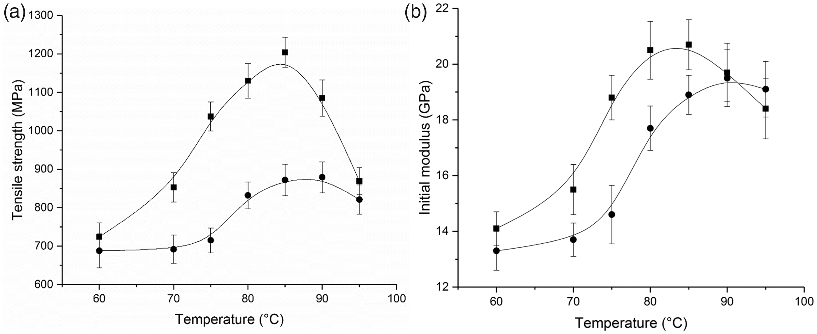


The hot-drawing process resulted in the transition from a lamellar structure of the as-spun filaments to a fibrillar structure of the fibers. The fibrillar structure consisted of crystal blocks connected by intercrystalline bridges. The fibrillar scheme is presented in Figure 19. Crystal blocks form with thin grains, and intercrystalline bridges form with extended molecular chains [43]. Lamellar destruction and strain-induced melting simultaneously occurred during the fibrillar structure formation. During the drawing process at a low temperature, the fibrillar structure mainly formed due to lamellar destruction. The effect of the strain-induced melting process became obvious as temperature increased [30]. If the fibers are drawn at the optimum temperature, the fibrillary structure formed by both lamellar destruction and strain-induced melting, in which the molecular chains are fully extended (as shown in Figure 9), then crystal regions form (as shown in Figure 11), crystal blocks form with the thinnest grains (as shown in Figure 15) and the orientation degree of the crystal structure is maximized (as shown in Figure 17). Therefore, U/H blend fibers and U fibers obtained the highest tensile strength and initial modulus at 85℃ and 90℃, respectively. However, the molecular chains will pull out of the blocks to which they were anchored if the drawing temperature exceeds the optimum temperature [48]; thus, the tensile strength and initial modulus of the fibers decreased when the drawing temperature exceeded the optimum temperature. Moreover, blending with HDPE improved the molecular chain orientation, crystallinity, grain shape and crystal orientation of the blend fibers. Therefore, U/H blend fibers had better mechanical properties than U fibers.
Schematic of the fibrillar structure inside the fibers.
Conclusions
The formation temperatures (including spinning temperature and hot-drawing temperature) of UHMWPE/HDPE-blend fibers prepared using the melt spinning method are found to have a significant influence on the microstructure and mechanical properties of the fibers, and this influence can be improved through blending with HDPE. During the spinning process, the molecular chain mobility of U/H as-spun blend filaments increases when spinning temperature is increased to the optimum spinning temperature, resulting in improved molecular chain orientation and crystallization ability. The optimum spinning temperature of U/H as-spun blend filaments is 310℃, at which point U/H as-spun blend filaments have the highest value of molecular chain orientation, crystallinity and crystal orientation. During the hot-drawing process, the stretchability of the molecular chains of the U/H blend fibers is enhanced when the hot-drawing temperature is increased to the optimum temperature, resulting in molecular chains that are easily drawn along the axial direction; thus, when U/H blend fibers drawn at the optimum temperature, the most fibrillary structure, consisting of thin grains that are mostly connected by extended molecular chains, is formed. The excellent mechanical properties of the U/H blend fibers benefit from the fibrillar structure. U/H blend fibers drawn at 85℃, the optimum drawing temperature for U/H blend fibers, have the highest tensile strength and initial modulus (1204 MPa and 20.7 GPa, respectively), which are 36.79% and 6.15% higher, respectively, than those of U fibers drawn at the optimum temperature.
Footnotes
Declaration of conflicting interests
The author(s) declared no potential conflicts of interest with respect to the research, authorship, and/or publication of this article.
Funding
The author(s) disclosed receipt of the following financial support for the research, authorship, and/or publication of this article: The authors would like to acknowledge the support of the National Natural Science Foundation of China (No. 51673021), the Higher Education and High-Quality and World-Class Universities (PY201609), and the Research Foundation for Youth Scholars of Beijing Technology and Business University (QNJJ2019-19).