
Abstract
In this study, the effect of curvature on the flexural behavior of 3D integrated woven fabric composites was initially investigated. After optimizing the effect of curvature, two strengthening methods (thickening upper skin and foam-filling) were applied on curved 3D integrated woven fabric composites separately and simultaneously. Normalized-weight flexural properties were used as an efficiency index to analyze and compare the efficiency of both methods. Results showed that as curvature increases from 0 to 0.007 and 0.014 cm−1, peak load increases about 29.8 and 36.7%, respectively. In addition, as upper skin thickness increases, most of flexural properties increase and then decrease. Moreover, flexural properties improved by injecting polyurethane foam into the empty core. Furthermore, applying both methods on curved 3D integrated woven fabric composite sample made an outstanding improvement in flexural properties. That is, the flexural peak load, stiffness, and total energy absorption increased 244.4, 142.7, and 496.4%, respectively, in comparison to the unreinforced 3D integrated woven fabric composite sample. Based on the normalized results, it could be concluded that applying thickening upper skin and foam-filling the core methods separately have no considerable improvement in specific flexural properties; however, applying both methods simultaneously improved specific peak load and specific total energy absorption 35.3 and 134.1%, respectively.
Keywords
Introduction
Sandwich composite panels made from three-dimensional woven fabrics have recently attracted researchers' attention. They could find vast applications in various industries such as aerospace, automotive, and construction industries due to their intrinsic properties like high specific strength and stiffness, low weight, thermal, and acoustic insulation [1,2]. Since these fabrics are produced only in a single stage, they are more cost-effective than conventional sandwich structures, honeycomb, and/or foam-core. Three-dimensional fabrics can be woven using velvet technique; they consist of two woven layers which are connected to each other by means of connecting yarns called “pile” [3,4]. 3D-woven fabrics resemble eight-shaped pile and one-shaped pile in the warp and weft directions, as shown in Figure 1, respectively [5].
A typical graphic of 3DIWF composite in the warp direction (left) and the weft direction (right).
One of the major merits of these types of composites in comparison with conventional sandwich composites is the superior core-skin binding. Consequently, these 3D panels show no delamination under different loadings [5]. There are various parameters that have considerable impact on mechanical performance of 3D integrated woven fabric (3DIWF) composites, such as core thickness, thickness of skins, pile density, pile structure, and load direction (weft or warp direction). The effects of these parameters on mechanical properties such as flexural, impact, compression, and shear properties have been investigated experimentally and numerically by many researchers. For instance, the effect of thickness (6, 9, and 17 mm) on low velocity impact property was investigated by Vaidya et al. [6]. They found that damage thresholds decrease as core thickness increases [6]. The effect of pile density on compression shear properties was studied by van Vuure et al. [7]. Their results showed that compression strength of 3DIWF composite is high and in order to improve the shear resistance to a satisfactory level, increasing the pile density could help [7]. Li et al. [8] carried out various mechanical tests on 3DIWF composites with different pile structure, pile height, and distribution density. They concluded that piles play a vital role in flatwise compression and shear properties, and their performance could be enhanced when the pile angle was about 80°–90°. Moreover, flatwise compression and shear strength of 3DIWF composites with big distribution density of low-height piles are superior. The flexural stiffness also increases as both pile height and density increase. Low velocity impact test was conducted on 3DIWF composite with different core thicknesses, and it was found that energy absorption decreases with the increment of core thickness [9]. Karahan et al. [10] investigated the effect of core thickness on bending and shear performance of 3DIWF composites. Their results showed that by increasing core thickness from 10 to 22 mm, both shear modulus and bending modulus reduce. Another study was experimentally and numerically carried out to study the mechanical behavior of 3DIWF composites [11]. Their results also show that low-height piles result in higher compressive stiffness, maximum stress, shear modulus, and yield stress, too. Moreover, Li et al. [12] performed bending test on 3DIWF composite in room and cryogenic temperature. They found that at liquid nitrogen temperature, bending properties have been improved considerably. In another study, they found that compressive properties from flat compression test were decreased by increasing core height while compressive properties from edgewise compression were increased [13]. Hosseini et al. [14] concluded that contact stiffness and perforation load reduce as thickness increases while energy absorption capacity increases. Charpy impact test was carried out by Li et al. [15] to investigate the 3DIWF composite at room and liquid nitrogen temperature. Their results showed that impact energy increases with the increment of core thickness at both temperatures and also impact properties improved considerably at liquid nitrogen temperature. Another study has been done by Kus et al. [16] on bending properties of 3DIWF epoxy/polyester-based composites at room and subzero temperatures. The epoxy-based composite showed higher bending properties than polyester-based composite at low temperatures; however, the overall bending properties improved at low temperatures. Also, a micromechanical modeling was proposed by Mirdehghan et al. [17] to predict the compression strength of 3DWIF composites. Their results showed that the strength of 3DWIF composites reduces as pile length increases. Besides, their proposed model could acceptably calculate the strength of piles.
Beside the mentioned advantages, there are two major drawbacks using 3DIWF composites. First, the skins are too thin (about 5 mm) to tolerate massive loads and they would soon buckle under flexural and impact loadings. In addition to skin, the empty core has a low shear resistivity [5] which causes the structure to perform weakly under compressive, impact, and shear loadings. In order to overcome the mentioned drawbacks and improve mechanical properties of 3DIWF composites, two useful methods were utilized by many researchers, injecting foam into the core and thickening the face sheets [10,18–21]. Their results showed that by introducing foam into the core, shear resistivity of the core could be improved. Therefore, the mechanical performance of foam-filled core 3DIWF composites has been improved significantly. This improvement is known to be a synergistic effect between piles and foam in the core [18–20]. For an example, the effect of foam and its density on bending performance of 3DIWF composites was investigated by Karahan et al. [10]. They found that by inserting foam in the core, flexural modulus and shear modulus increase dramatically. Moreover, flexural modulus and shear modulus increase as foam density increases. On the other hand, other studies showed that face sheet thickness is a vital parameter influencing mechanical performance of 3DIWF composites [18,20,21]. For instance, Li et al. [20] investigated the effect of thickening face sheets on mechanical properties of 3DIWF composites. Their results revealed that by thickening the face sheets, with or without foam in the core, the bending load-bearing capacity could be improved considerably. Furthermore, another study concluded that edgewise compressive and impact properties proposed a significant improvement compared to non-thickened face sheets [21]. Hu et al. [22] carried out experimental investigation on the failures of 3DIWF composites. They reported that to attain face-sheet failure mode by long beam flexure, the span must be higher than 36 times of composite's thickness [22].
Beside using conventional sandwich composite in flat form, they could be fabricated and used in curved beam form. The effect of curvature on the mechanical and vibration performance of curved conventional sandwich beams was investigated by many researchers [23–27]. In aforementioned studies, it was shown that the effect of shear deformation reduces as curvature increases. For instant, the results of three-point bending test results show that by introducing a small curvature (e.g. θ = 15°), the peak load at failure increases while by raising curvature up to 60°, it decreases [26]. Since conventional sandwich composites have weak out of plane properties and skin/core debonding is still concerning, the core could be reinforced by pins like pultruded carbon fiber rods. In this regard, Haldar et al. [27] studied bending behavior of pin reinforced curved sandwich composite experimentally and numerically. It is true that pin insertion in the core direction could improve the out of plane properties and avoid the core/skin debonding, but the fabricating process took more time when compared to 3DIWF composites [27]. Thus, in the following, an attempt is made to use three-dimensional integrated woven fabrics made of glass rovings as curved sandwich panels, since these fabrics are currently available and have good specific mechanical properties. Besides, due to the lattice structure in the core, it can be filled by appropriate materials to make it a multifunctional curved sandwich structure.
On the whole, 3DIWF composites could be a promising sandwich structure to be used as an alternative instead of conventional sandwich composites. As can be seen, many researchers have investigated the effect of various parameters on mechanical behavior of 3DIWF composites. Since these composites have potential to be used in construction industry as light-weight curved-shape structures like emergency shelters, in this study, the effect of curvature on the flexural behavior of 3DIWF composites was initially investigated. The reason for investigating the effect of curvature lies in the fact that there may be an optimum value or range for radius of curvature in which the flexural properties of curved panels are going to be superior than the flat ones. Moreover, considering the fact that there is no scientific research in the literature focusing on comparing different strengthening methods of 3DIWF composites (e.g. thickening of skins vs. modifying of core), thus the question is which method is more efficient in improving the mechanical properties like bending, shear, and compression property. Therefore, after optimizing the effect of curvature, both mentioned methods were applied on curved 3DIWF composites separately and simultaneously. In order to analyze and compare their efficiency correctly, normalized-weight flexural properties were used as an efficiency index.
Experimental works
Materials
Some important characteristics of 3DIWF.

Other materials such as E-Glass woven fabric and two-part polyurethane (PUR) foam were used in order to reinforce the upper skin and the core section of the composite specimen. Area density, warp, and weft density of E-Glass woven fabric were 600 g/m2 and 3 cm−1, respectively. Two-part PUR foam, polyol (1.08 g/cm3) and isocyanate (1.23 g/cm3), were mixed together using mixing ratio of 1:1. Fiberglass mat (areal density of 450 g/cm2) was also used to fabricate curved composite mold.
Mold fabrication
Flat and curved molds were used to fabricate flat and curved composite specimens, respectively. Curved composite molds (with different radius of curvatures) were fabricated on various curved surfaces using E-Glass woven fabric, fiberglass mat, and polyester resin by hand layup method. Consequently, curved composite specimens were fabricated and cured on curved composite molds in indoor conditions (24℃ and 60% relative humidity (RH)).
Flat and curved composite specimen fabrication
Flat and curved specimens were fabricated using hand layup technique. In the following, flat specimens are referred as EF, and curved specimens with the radius of curvature of 150 cm−1, 70 cm−1, and 35 cm−1 are referred as EA, EB, and EC, respectively, as also presented in Table 2. As shown schematically for fabricating curved sample in Figure 2, initially certain amount of mixed epoxy resin (30% wt) was distributed on the mold surface uniformly. Then, the 3DIWF was impregnated uniformly with mixed epoxy resin on corresponding flat or curved mold using a roller. Finally, the upper skin was drawn to form the ultimate three-dimensional structure of curved or flat 3DIWF composite sample. Note that pile yarns were smeared to resin by capillary absorption of epoxy resin through both the skins during composite fabrication. Subsequently, the flat or curved composite samples were cured at room temperature (24℃ and 60% RH) for 24 h. Each cured composite sample was cut into three specimens in proper dimensions using circular saw ultimately. Flat and curved composite samples are graphically shown in Figure 3(a).
A schematic of fabricating a curved 3DIWF composite. (a) Flat and curved composite samples and (b) thickened face-sheet and foam-filled composite samples separately (EB-2L, EB-4L, and EB-PU) and simultaneously (EB-4L.PU). Characteristics of composite samples. aPresented values are average of three specimens. Values presented in the parentheses are standard deviations.


Thickened face-sheet composite specimen fabrication
The aim of fabricating thickened face-sheet composite was to investigate the effect of the upper skin thickness on flexural properties. In order to fabricate curved thickened face-sheet composite samples, the upper skin of the semi-cured curved composite was thickened by E-Glass woven fabrics and epoxy resin using hand layup technique described previously. Thickened face-sheet composite samples with two layers and four layers of E-Glass woven fabric are referred to as EB-2L and EB-4L, respectively, in the following, as shown in Table 2. Consequently, the curved thickened face-sheet composite samples were cured for a day in indoor conditions (24℃ and 60% RH) for all samples. Finally, the cured samples were cut into three specimens in proper dimensions. Thickened face-sheet composite samples are shown in Figure 3(b).
Foam-filled core composite specimen fabrication
Foam-filed core specimen was fabricated in order to investigate the effect of the presence of foam in the core on flexural properties of 3DIWF composites and compare it to the thickened face-sheet composite sample. To prepare foam-filled core composite sample, after mixing two parts of PUR foam, it was injected into the core of cured curved composite sample. It was consequently kept in an insulated chamber under pressure to ensure that the core is fully filled by the foam. The foam-filled core sample was kept at room condition for one day. Foam-filled core composite sample is referred to as EB–PU in the following, as shown in Table 2. Finally, the prepared sample was cut into three specimens in proper dimensions. A foam-filled core composite sample is shown in Figure 3(b).
Foam-filled core thickened face-sheet composite specimen fabrication
Foam-filled core thickened face-sheet composite sample (referred to as EB-4L.PU in the following) was fabricated to investigate the effect of both methods on flexural properties. Thus, at first, thickened face-sheet composite sample was fabricated as described previously. PUR foam was consequently injected into the core of the thickened face-sheet composite and kept for 24 h at indoor conditions (24℃ and 60% RH). Finally, the foam-filled core thickened face-sheet sample was cut into three specimens in proper dimensions. A foam-filled core and thickened face-sheet composite sample is shown in Figure 3(b).
Three-point bending test
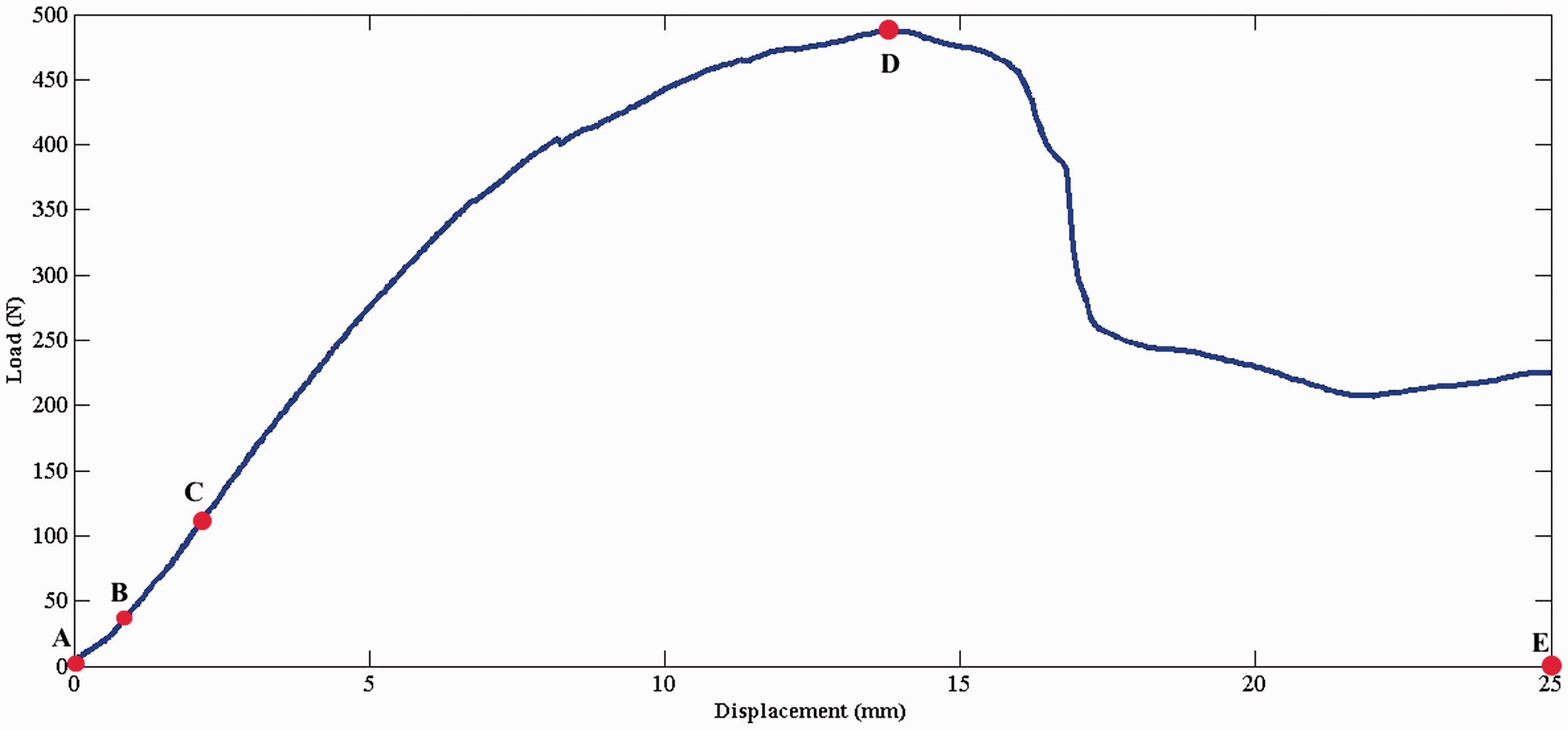
Flexural properties of curved and flat composite samples were investigated via carrying out three-point bending test according to ASTM C3933. The bending test was performed on Hounsfield test machine with load cell of 25 kg and displacement rate of 3 mm/min. The dimensions of curved/flat composite specimen were 100 and 300 mm in width and length, respectively. Characteristics of composite samples are presented in Table 2. Three-point bending loading on composite samples, which was performed in warp direction, is schematically shown in Figure 4(a). It should be noted that the span length of bending test setup is 250 mm for all samples. Flexural properties are obtained through three-point bending test such as peak load, stiffness, and total energy absorption. A typical flexural load–displacement diagram for 3DIWF composite samples is shown in Figure 5. According to Figure 5, peak load is defined as the highest load attained (mark D), and stiffness is defined as the slope between the origin point B and point C. Moreover, total energy absorption is defined as the area under the curve between the origin point 0 mm (mark A) and point 25 mm (mark E), along the displacement axis.
(a) A schematic of three-point bending and (b) types of stresses imposed on 3DIWF composite sample under three-point bending. A typical flexural load–displacement curve of curved 3DIWF composites.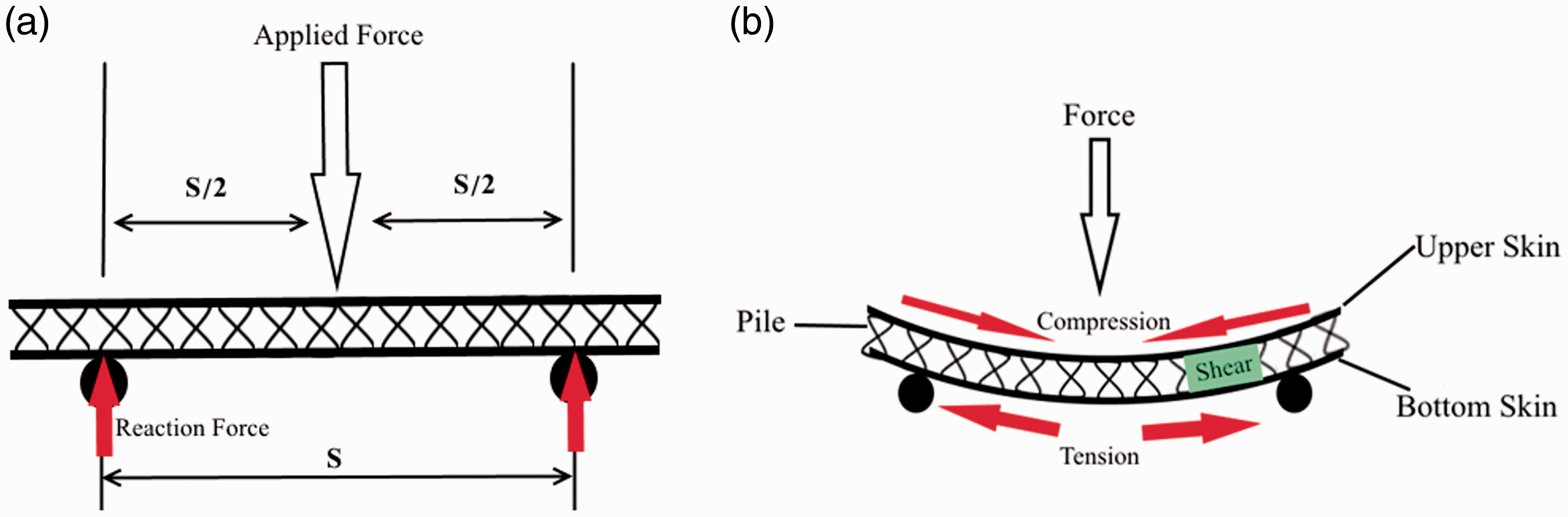
Fiber volume fraction of composite samples
Standard test method for constituent content of composite materials, ASTM D3171, was applied to determine the constituent content of composite samples [28]. Following the instruction, at first, the matrix part was removed physically through ignition which left reinforcement part intact. Therefore, the calculation of reinforcement or matrix content (by weight or volume) would be possible. Using following equations, content of reinforcement part (by weight) and then matrix part (by weight) could be determined


Fiber volume fraction (FVF) of composite samples.
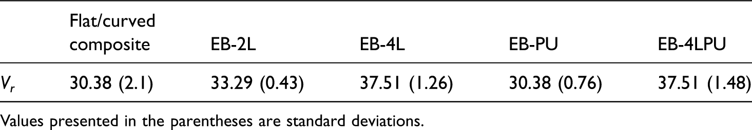
Values presented in the parentheses are standard deviations.
Theoretical modeling
In what follows, the flexural bending behavior is analyzed using a theoretical model based on strength of materials method. A typical curved 3DIWF composite under three-point bending loading is schematically shown in Figure 6(a). The sample is simply supported at points A and B (vertical movements are constrained), and an external load P is applied on point C. It can be understood from free body diagram that the structure is statically determinate. Thus, reacting forces on points A and B (R
A
and R
B
) can be derived using balance law and both are equal to A schematic of a curved 3DIWF composite under three-point bending loading.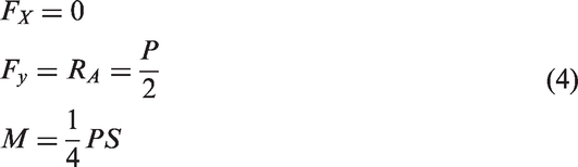


Since

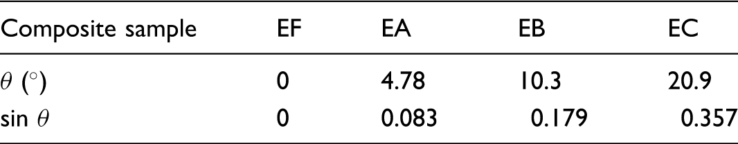
The value of angle θ could be calculated for each curved 3DIWF composite sample using equation (6). Now an arbitrary point (D) on AOC segment, as shown in Figure 6(c), is considered to derive internal forces and internal moments
Flexural strength comparison of flat and curved composite samples.


Results and discussion
Modes of failure in bending test
Three types of stresses will be induced when 3DIWF composite samples are exposed to three-point flexural loading, as shown in Figure 4(b). These stresses are namely compression, shear, and tension which act on the upper skin, the core, and the lower skin of 3DIWF composites, in that order [9]. During three-point bending test, two types of failure have been observed: buckling failure which has occurred on the upper skin of the sample due to the development of compression stress and shearing failure which has occurred in the core of the sample due to the development of shear stress. Based on the observations, buckling failure starts and develops under the point of applied load where shearing failure starts and develops in a domain between the point of applied load and the point of support load. Both aforementioned failures are shown in Figure 8. No failure or cracks have been observed in the lower skin, even at larger displacements, during three-point bending tests.
Two modes of observed failure in curved composite samples due to (a) compression and (b) shear.
In flat composite specimens, only upper skin buckling failure has observed, while in curved composite samples, both types of mentioned failures have been witnessed. The occurrence and development of both failures in curved samples are represented graphically in Figure 10. The load–displacement curve manner is the only distinction between these two failures which is shown in Figure 11. As can be seen, the flexural load for the sample with shear failure in the core increases gradually with less slope compared to the one with buckling failure. Moreover, the load–displacement curve for sample with the buckling failure consists of two regions and a sudden load drop, which is due to buckling of the upper skin, while for the sample with shear failure, there is a long plateau. Besides, the load–displacement curve behavior, the flexural properties measured from these failures are considerably different. In order to understand why shear failure only happens in curved composite samples, a schematic of curved composite sample under three-point bending loading is indicated in Figure 9(a). There is a distinct difference between a curved composite sample under three-point bending loading and a flat one. For flat 3DIWF composite sample under three-point bending loading, the occurrence of buckling failure is dominant because reaction force is perpendicular to the sample and has no resultant, as shown schematically in Figure 4(a). On the other hand, applying the same condition on a curved composite sample, even in the initial stage, support force is not perpendicular to the sample. Therefore, support force could be divided into two components, Fsin θ and Fcos θ, which are called shear and compression resultant forces that cause shear stress in the core and compression stress in the lower skin, in that order. It should be noted that lines AO and BO are the radius of curvature of curved 3DIWF composite, which are normal to the lower skin. As depicted in Figure 9(b), the angle θ is the angle between lines AB and AC. Since angle θ and angle α are complementary, angle α could be calculated easily using equation (11)
(a) Schematic of curved composite sample under three-point bending and (b) support force resultants. The occurrence and development of shear failure (a–d) and buckling failure (e–g). The load–displacement curve manner of composite samples experiencing shear (sample EB marked as blue line) and buckling failure (sample EA marked as green line). The value of θ respect to curvature.


Stress variation can be plotted along thickness using equation (10) by considering a constant value for α. Stress variation for curved 3DIWF composite samples for Stress variation of curved 3DIWF composite samples ( Stress variation along specimen length in upper skin for EB composite sample.

Load–displacement diagram
Similar trend in load–displacement diagram has observed for all flat and curved composite samples, as depicted in Figure 14. Almost most of diagrams have experienced sudden drop in flexural load which is due to the buckling of the upper skin. However, some of the curved sample (mostly EC samples) experienced shear failure under three-point bending, as discussed in the previous section. All load–displacement diagrams consist of two regions which are elastic and plastic regions. In this study, elastic/plastic regions are considered as regions before/after the occurrence of sudden flexural load drop. All flat and curved composite samples showed linear trend up to sudden load drop in elastic region. In the plastic region, after experiencing sudden drop in flexural force, the load stays constant for all composite samples as displacement increases.
Comparison of force–displacement curve for flat/curved composite samples.
Thickening the upper skin thickness causes a considerable change in load–displacement diagram compared to composite sample without thickened upper skin, as illustrated in Figure 15. In other words, load–displacement diagram of thickened upper skin samples showed no sudden flexural load drop, which means they experienced no buckling in the upper skin. By increasing the thickness of the upper skin from 0.5 to 2 mm, the load–displacement diagram still shows linear trend up to maximum flexural load in the elastic region. Since no buckling failure has occurred in the thickened upper skin and consequently no sudden flexural load drop has observed in load–displacement curve, in plastic region, the flexural load remains constant with the same magnitude of maximum flexural load as displacement increases. Further increasing in upper skin thickness, from 2 to 3 mm, results in a slight change in load–displacement curve trend, as can be observed in Figure 15. Both EB-2L and EB-4L diagrams have exactly the same slope in the initial part of the curve in elastic region, but the curve slope of EB-4L samples changes at displacement about 3 mm.
Force–displacement comparison of curved 3DIWF composites strengthened by two methods separately.
Injecting PUR foam into the core of 3DIWF curved composite sample did not change load–displacement diagram compared to empty core sample, as shown in Figure 15. In other words, there is still a sudden flexural load drop in the curve due to the upper skin buckling failure. In the elastic region, foam-filled composite sample still shows linear trend up to the maximum flexural load; however, its slope is more than empty core composite sample. In addition, the curve stays above the empty core composite sample in the plastic region and has a similar load–displacement trend in this region. Displacement up to failure in the elastic region for the foam-filled composite sample is less than the empty core composite sample. This behavior indicates that bending behavior of foam-filled composite sample is more ductile than empty core composite samples.
Load–displacement diagram of EB-4LPU composite sample is similar to thickened upper skin composite samples, as described in Figure 16. That means there is no sudden flexural load drop, as expected. Filling the empty core of thickened upper skin 3DIWF composite sample with PUR foam made a significant change in flexural load–displacement curve. The flexural load increases as displacement grows up with much greater slope than other curved 3DIWF composite samples. The subsurface area of load–displacement diagram in the elastic region, which indicates absorbed energy before reaching the peak flexural load, is much greater for EB-4LPU than other samples. Moreover, this trend is true in the plastic region.
Force–displacement comparison of curved 3DIWF composites strengthened by two methods simultaneously.
Flexural properties
Three-point flexural test results for composite samples.
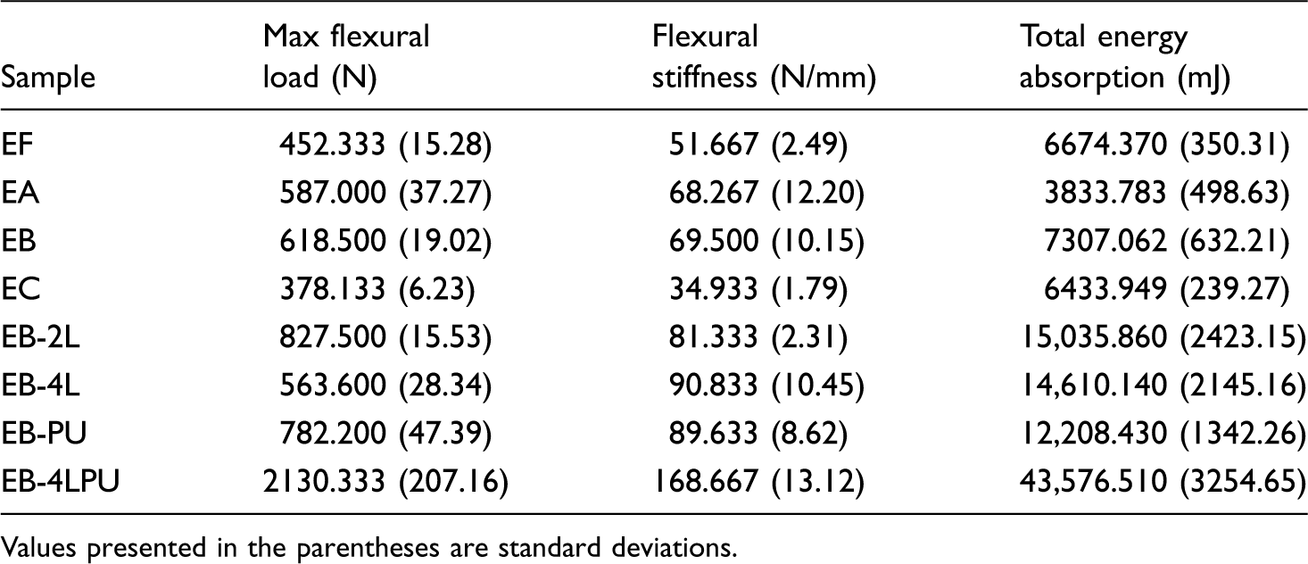
Values presented in the parentheses are standard deviations.
A typical t-test test result on peak load between pair groups.

*The difference is significant at the significance level of 0.05.
Therefore, three different types of curved 3DIWF composites were fabricated using two aforementioned methods separately and simultaneously for the reason that both failures have been observed in curved 3DIWF composites and due to lack of proper information on comparison between improvements made by both methods. In the case of thickening the skin of curved 3DIWF composites, only the upper skin was thickened due to the experimental observations that no cracks have been observed in the lower skin of the samples. Moreover, the effect of upper skin on the flexural properties was investigated by preparing two curved composite samples with the upper skin thickness of 2 and 3 mm. Overall, four different samples were fabricated and cut into proper dimensions to prepare for three-point bending loading. In the following, the effect of both methods, separately and simultaneously, on flexural properties of curved composite samples will be discussed.
The effect of upper skin thickness
Since upper skin failure is common in three-point bending loading due to the very low thickness which causes high stress on upper skin, so thickening the face sheets is an option to enhance load-bearing capability of 3DIWF composites. In the current study, no cracks have been observed in the lower skin; therefore, only the upper skin was thickened while in most of literatures, both skins were thickened [17,19,20] which seems unnecessary. Two different upper skin thicknesses were considered in this study which their fabrication and characteristics have already been presented in “Thickened face-sheet composite specimen fabrication” section.
According to Table 5, as upper skin thickness increases, most of flexural properties increase and then decrease. In other words, both peak load and total energy absorption have similar trend. However, stiffness increases as upper skin thickness increases. For instance, peak load increased 33.8% as upper skin thickness increases from 0.5 to 2 mm and then decreases 8.8% by upper skin thickness increment to 3 mm, in comparison to the sample without thickened upper skin. It should be noted that fiber volume fraction will increase as upper skin thickness increases. The upper skin buckling failure of curved 3DIWF composite could be avoided with increasing the upper skin thickness; therefore, the thickened upper skin composite sample would experience shear failure in the core. A typical shear failure behavior of thickened upper skin curved 3DIWF composite sample is graphically shown in Figure 17. The upper skin of the composite sample with and without thickened upper skin after unloading is presented in Figure 18. It can be observed that the damaged area caused by applying flexural load is much smaller for the composite sample with thickened upper skin compared to the one without thickened upper skin. By comparing the obtained results for both thickened upper skin composite samples, it can be concluded that the upper skin thickness has an optimum value which is about 2 mm. The reason is that no significant improvement would be achieved by further increasing the upper skin thickness. It is believed that the upper skin thickness of 1–2 mm is sufficient, since the empty core has a low shear resistivity.
Shear failure of thickened upper skin 3DIWF composite. Comparison of the upper skin of 3DWF composite samples with (a,b) and without (c) thickened upper skin.

The effect of PUR foam in the core
Since shear failure in the core is more probable in curved 3DIWF composite samples under three-point bending loading due to the reasons discussed in “Modes of failure in three-point bending” section, so filling the core with foam material is an alternative option to enhance load-bearing capability of sandwich composites. In this regard, one curved 3DIWF composite sample with foam-filled core was fabricated as explained in “Foam-filled core composite specimen fabrication” section.
Flexural properties have been improved by injecting PUR foam into the empty core, based on the obtained results. In other words, the flexural peak load, stiffness, and total energy absorption increased due to the presence of foam in the core. For instance, as presented in Table 5, by adding foam into the core, the flexural peak load, stiffness, and total energy absorption increased 20.9, 22.5, and 67.1%, respectively. This improvement is caused by the synergistic effect of piles and foam in the core of 3DIWF sandwich composite. Consequently, core shear failure could be avoided in the curved sandwich composite samples by filling the empty core with PUR foam; however, the composite sample experienced upper skin buckling failure. A typical upper skin buckling failure behavior of foam-filled core curved 3DIWF composite sample is graphically shown in Figure 19. The upper skin of composite sample with and without PUR foam in the core after unloading is presented in Figure 20. When the results obtained for thickened upper skin and core foam-filled 3DIWF composite samples are compared, it can be concluded that thickening the upper skin improves load-bearing capacity of the structure more than filling the core with foam. Although, filling the core with PUR foam enhances the stiffness of the structure more than thickening the upper skin. One of the outstanding advantages of 3DIWF composites is recovering to their initial shape after unloading. The unreinforced and thickened upper skin 3DIWF composite samples show this property quite well while EB-PU and EB-4LPU were not better than the empty core composite samples, as could be observed in Figure 21.
Buckling failure of foam-filled core 3DIWF composite. Comparison the upper skin of 3DIWF composite sample with (a) and without (b) foam in the core. Recovery of 3DIWF composite samples after unloading: (a) EB-2L, (b) EB-PU, and (c) EB.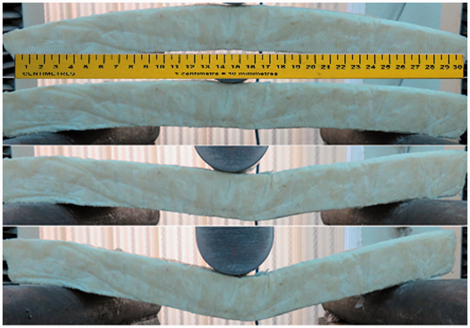


The effect of foamed-core thickened upper skin
Since flat composite samples only fail due to upper skin buckling, therefore thickening the upper skin, based on the results of the current study, seems to be superior method. For the curved composite sample, reinforcing the empty core by foam could not improve the properties as much as upper skin does. Thus, finally both mentioned methods were applied on curved 3DIWF composite sample. The fabrication procedure and characteristics of the thickened upper skin 3DIWF composite with foam-filled core (EB-4LPU) have been discussed in “Foam-filled core thickened face-sheet composite specimen fabrication” section.
As can be seen, applying both methods on curved 3DIWF composite sample made an outstanding improvement in flexural properties. That is, the flexural peak load, stiffness, and total energy absorption increased 244.4%, 142.7%, and 496.4%, respectively, in comparison to the unreinforced 3DIWF composite sample. By comparing thickened upper skin 3DIWF composite with and without foam-filled core, the importance of presence of foam in the core in order to obtain desired flexural properties could be understood. Beside the synergistic effect between piles and PUR foam in the core, there is also another synergistic effect between thickened skins and PUR foam in the core, based on the results. The flexural behavior of EB-4LPU composite sample is graphically shown in Figure 22.
Flexural behavior of EB-4LPU composite sample.
Moreover, t-test was performed on experimental data to investigate the effect of applied methods on flexural properties of composite samples. The statistical results indicated that there is significant difference between some groups. T-test results on peak load indicated that applying both methods on 3DIWF composites and applying only the thickening method (increasing upper skin thickness from 0.5 to 2 mm) have significant effect on peak load. On the other hand, filling the empty core with PUR foam and thickening the upper skin from 0.5 to 3 mm have no significant effect on peak load. However, same test results on stiffness showed that only applying both methods on 3DIWF curved composite sample have significant effect on stiffness. Moreover, filling the empty core with PUR foam has no significant effect on total energy absorption while thickening the upper skin and applying both methods improved total energy absorption significantly.
Performance of different methods
Specific flexural properties of 3DIWF composite samples.

T-test test was also carried out on experimental data to investigate the effect of applied methods on specific flexural properties. The obtained results from t-test on specific peak load showed that thickening the upper skin from 0 to 2 mm and filling the empty core with PUR foam did not improve specific peak load significantly. However, applying both methods had significant effect on specific peak load. On the other hand, thickening the upper skin from 0 to 3 mm deteriorates specific peak load significantly. Same test results on specific stiffness indicated that filling the empty core with PUR foam and applying both methods have no significant effect on specific stiffness while thickening the thickness reduced the specific stiffness significantly. For specific total energy absorption, applying both methods had significant improvement.
Conclusion
In this study, curved 3DIWF composites were successfully fabricated, and their flexural properties and behavior were analyzed and compared to flat 3DIWF composites. At first, the effect of curvature on flexural properties and behavior was investigated. After finding the optimum value for curvature, two strengthening methods were offered (e.g. thickening of skins vs. modifying of core) and applied on curved 3DIWF composites separately and simultaneously. Finally, in order to achieve a better understanding of which method has better improvement in flexural properties, flexural properties were consequently normalized by composite samples weight. The results showed that:
By adding and increasing curvature up to 0.014 cm−1, flexural properties increase too. While, by further increasing curvature from 0.014 to 0.028 cm−1, flexural properties decrease. For instance, as curvature increases from 0 to 0.007 and 0.014 cm−1, peak load increases 29.8 and 36.7%, respectively. With further increase in curvature, peak load decreases 16.4% when compared to sample EF. As upper skin thickness increases, most of flexural properties increase and then decrease. In other words, both peak load and total energy absorption have similar trend. However, stiffness increases as upper skin thickness increases. For instance, peak load increased 33.8% as upper skin thickness increases from 0.5 to 2 mm and then decreases 8.8% by upper skin thickness increment to 3 mm, in comparison to the sample without thickened upper skin. Flexural properties have been improved by injecting PUR foam into the empty core, based on the obtained results. For instance, by adding foam into the core, the flexural peak load, stiffness, and total energy absorption increased 20.9, 22.5, and 67.1%, respectively. Applying both methods on curved 3DIWF composite sample made an outstanding improvement in flexural properties. That is, the flexural peak load, stiffness, and total energy absorption increased 244.4%, 142.7%, and 496.4%, respectively, in comparison to the unreinforced 3DIWF composite sample. The upper skin buckling failure of curved 3DIWF composite could be avoided with increasing the upper skin thickness; however, the composite sample experienced shear failure in the core. Moreover, the damaged area caused by applying flexural load is much smaller for the composite sample with thickened upper skin compared to the one without thickened upper skin. Core shear failure could be avoided in the curved sandwich composite samples by filling the empty core with PUR foam; however, the composite sample experienced upper skin buckling failure. One of the outstanding advantages of 3DIWF composites is recovering to their initial shape after unloading. The unreinforced and thickened upper skin 3DIWF composite samples show this property quite well while for EB–PU and EB–4LPU, it was not as good as the empty core composite samples. Applying thickening upper skin and foam-filling the core methods separately have no considerable improvement in specific flexural properties. However, applying both methods simultaneously improved specific peak load and specific total energy absorption 35.3 and 134.1%, respectively. Based on the findings of the current study, curved 3DIWF composite panels could be used as lightweight shell structures, even without frames since they can keep their shape and integrity under loadings. Besides, loads applied to the surface can be carried to the ground by the development of compressive, tensile, and shear stresses in the in-plane direction of surface. Other type of shell structures such as barrel vault can be made by joining a specified number of curved 3DWIF composite panels. Moreover, curved 3DIWF composite panels can be used as a promising reinforcement in curved concrete structures.
Footnotes
Data availability
The raw data required to reproduce these findings are available to download from doi:10.17632/79gy5gvb25.2.
Declaration of conflicting interests
The author(s) declared no potential conflicts of interest with respect to the research, authorship, and/or publication of this article.
Funding
The author(s) received no financial support for the research, authorship, and/or publication of this article.