
Abstract
Tubular woven fabric can maintain a certain two-layer hollow height-alterable structure by heat setting, which quickly and effectively fills various materials, especially for the soft down feather. Therefore, by designing the pattern structure, a variable structure tubular fabric was designed and prepared by weaving equipment. We obtained a two-layer hollow height-alterable fabric by the heat-setting method and constructed a compression theory model. The compression process designed in this paper is the bending process of the fabric, so the bending deformation can be simplified into that of an elastically bent elastic rod. The results show that the theoretical curve and the actual compression curve are more consistent in the compression within strain 50%. The influence of key structural parameters on the compression performance of tubular fabric was also studied. On the basis of the model, the influence of material properties on the compression performance of tubular fabric was also discussed. The paper can provide theoretical guidance for the development of tubular fabrics with high hollow ratio and compression resistance in industrial textiles.
Introduction
With the development of textile engineering and advanced manufacturing engineering, tubular woven fabric is a kind of three-dimensional fabric with spatial hollow structure [1,2]. So it is gradually popular as a new product of industrial textiles because tubular fabric can be made of lightweight, high-strength, and high modulus fiber material. It can be widely used in the production of various pipeline, shell, bushing, super high temperature resistant heat insulation pipe, and various structural supports. Especially for spatial structure with high hollow ratio, the tubular fabric has excellent shape stability, uniformity, relatively high strength, and high production efficiency compared with the existing down clothing fabric on the market. At present, most of the down jackets are made of two pieces of fabric by sewing, which are flat and their formed tubular shape is unstable due to deformation. Therefore, it is more popular to use the tubular knot fabric as a down jacket, which can solve the problem of anti-drilling velvet and make the process of down stable. The key is the compression properties of tubular fabrics. At present, tubular fabrics are more concentrated on the tracheal stent [3,4], the mechanical properties of the tubular fabric and so on [5,6]. Many researchers studied the compression property about woven fabric [7–10], nonwoven fabrics [11], and knitted fabrics [12–18]. Though the structures of fabrics are different, the key of these fabrics is the compression properties.
Some researchers presented the basic compression theory for fiber assembly fabrics, which aimed to observe how the structure of a yarn or a fabric influenced its compressibility before finishing [8,19,20]. They found that the curve of compression was independent of the fiber arrangement when a yarn was made. Matsudaira and Qin [21] presented a theoretical model of compression deformation of fabric. This theory regarded silk or fiber and air as combination. The compressive resistance comes from the transverse compression of the fiber itself, and the compression curve can approximate to several linear equations. Kothari and Das [11] presented compression property of nonwoven fabrics and obtained the equation of the compression process curve. Soe et al. [15] analyzed the plain knit fabrics based on two linear functions. The above research theory seems to be difficult to apply to high-elastic tubular fabric, and this paper uses elastic rod principle to analyze structure and compression of tubular fabrics.
Therefore, in this paper, the tubular fabric undergoes heat setting to maintain the tubular form. It is of great significance to the filling of the feathers and the use of the down clothes. The relationship between the tubular structure parameters and the compression properties is discussed through the design and weaved into thermal finalized tubular fabric. The article focuses on the significance of the compression properties of tubular fabrics after heat setting. The key is to perform the compression performance analysis for heat-shape tubular fabrics. This topic is of great significance for the design of compression structure of tubular fabric. The thermal conductivity of tubular fabric will be analyzed theoretically in this series of paper.
Theoretical analysis of compressive property of tubular bonding fabric
Compression experiment
As shown in Figure 1, compression tester JA12002 is chosen to conduct plane plate compression. Compression speed is set as 12 mm/min. Plate indenter connected with a force sensor is driven by motor fixed in the main frame so as to compress tubular fabrics pasted on the surface of the plane plate. The plane plate is a circle with diameter of 24 cm. For compression test, double-side adhesive tapes are chosen to stick part of tubular fabric on the surface of the plane plate to avoid slippage phenomenon. In order to have a good comparison, compression tests of tubular fabrics are conducted to the same maximal compression load.
Plane plate compression of tubular fabric.
Theoretical analysis
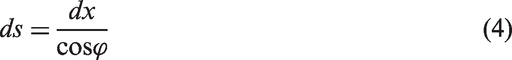
Considered the compression of tubular fabric to be like a flexible rod, the compression deformation of fabric is similar to the bending deformation of an elastic rod [22,23]. That is, it is assumed that in the compression process, the fabric only occurs completely elastic bending deformation, the torsion of the elastic rod, and the axial compression deformation are ignored, therefore, the length of the fabric can be assumed to remain the same when the pressure is increased. It is assumed that the bending of a single elastic rod is completely caused by the compression force. According to the theory of elastic mechanics and the symmetrical compression deformation of tubular fabric in Figure 1, the right half part of tubular fabric is chosen as shown in Figure 2, the Cartesian coordinate is set with x-axis and y-axis. The curvature at any point C on the elastic rod can be expressed by the bending moment and the bending rigidity. The definition of the curvature is
Right half part of tubular fabric as elastic rod.

In the equation, ϕ is the angle of the tangent at any point C on the elastic rod to the x-axis; s is the arc length at any point C on the elastic rod; B is the bending rigidity of fabric in bending direction; M is the bending moment at point C;
Because M = Fx, F is the force acting on both ends of the elastic rod, and x is the displacement in the vertical direction.

By letting b2 = B/F, we obtain

Because
By substituting equation (4) into equation (3), equation (3) becomes

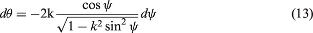
Get the integral from the A point. We obtain

α is the angle between the tangent and the y-axis at the end point A
After the integration

By letting

By substituting equation (9) into equation (8), it has

Equation (10) is simplified into equation (11)

By substituting equations (5) and (11) into equation (3), it yields

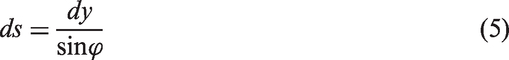
According to equation (9), we have
By substituting equation (13) into equation (12), equation (12) becomes

Starting the integral from the point B and combining the boundary condition, equation (15) is yielded.
At point B,
Thus

After the integration

In the equation

F
Substituting equations (11) and (13) into equation (3), equation (3) becomes

Starting the integral from point A, and combining the boundary condition, equation (20) is yielded.
At point A,

After the integration


Boundary conditions
According to equations (17) to (21), boundary conditions of points A and B are yielded.
At point A:
At point B:
Calculation of length
The length of the elastic rod from point A to point B

For b2 = B/F, thus we have equation (25).

For a given length of monofilament, by letting
And F/W is a dimensionless value. At point A, it has


Numerical analysis
As shown in Figure 3, the thickness of the tubular binding fabric is compressed, in which the monofilament is bent into an arc ABA′.
Monofilament bending process.
The value of YA/SAB and F/W in the bending.

As shown in Figures 2 and 3, after α reaching 90°, as the thickness decreases, the included angle no longer decreases. AC in the monofilament ABA′ are in a straight line. The elastic bending under the pressure F is only CB section, with the pressure increases, the thickness decreases, the effective bending monofilament CB section continues to shorten until the fabric collapse, monofilament is radial compressed for it cannot be bent.
Partial value of XA/SAB and F/W in the second stage of single-wire bending.

Combining the theoretical data in Tables 1 and 2, the stress–strain curves of monofilaments perpendicular to the x-axis (at 90°) were plotted in Figure 4. For a given feedstock and length of monofilament, W is a constant and proportional to the bending stiffness B and inversely proportional to the square of the length S
2
AB; (1 − XA/SAB) is the compressive strain. Thus, the monofilament on the surface of the tubular junction fabric is almost linear within 50% of the compressive deformation range. The greater the stiffness of the monofilament, the thicker the rod, the more the pressure required to produce the unit deformation. When the deformation is over 50%, the external force and strain become into nonlinear change; when the strain exceeds 80%, the force bending deformation curve showed a linear change. In fact, during practical use, the bending deformation of the monofilament usually be within 50% of the linear area. The fabric can show good bending elasticity and its elastic recovery performance is very good, the bending damage of the fabric is relatively small, it will not affect the fabric seriously.
Theoretical dimensionless compression force–strain curve of monofilament.
Experimental
Experimental materials
Fabric specifications: Polyester tubular knot fabric, the warp yarn with a diameter of 0.17 mm polyester monofilament, weft yarn using 50 S/2 polyester yarn, warp, and weft yarns arrangement density being 500 threads/10 cm and 360 threads/10 cm, warp and weft tightness being 85% and 45%, and the total tightness is 91%. Designed sample width is 12 cm.
Samples preparation
In order to study the microstructure size effect on fabric compressive elasticity, four kinds of fabrics were designed, while the width channel of the designed tubular fabric is different. Four samples obtained by weaving as in Figure 5 and specification of tubular fabric channels are shown in Table 3.
Device for a rapier loom. Specification parameters of different tubular fabric channels.

Heat setting of tubular fabrics
The interior of the tubular fabric was filled with the floc and then the fabric was heated for 190℃, 45 min and shaped under standard atmospheric condition. The tubular fabric was heat-set before and after the fabric sample, as shown in Figure 6.
Fabric samples of tubular fabrics (a) without heat setting and (b) with heat setting.
Compression test
Compression performance of different structures of the same kind of tubular fabric is greatly different. Constant pressure plate compression tests were for the four kinds of fabric without and with heat setting. A certain index in the curve was extracted to analyze the relationship between the compressing parameters of different samples and structure influence on the compressing performance. The eight kinds of samples with different structural and stereotyped effects were cut into rectangular fabrics with a width of 10 cm. Flat compression is shown in Figure 1. It is briefly summarized as follows: (1) For the sample without and with heat setting, the experiment adopts the method of constant pressure test according to Chinese Standard FZ/T 01051.1-1998. In order to ensure the accuracy of the final compression curve, each sample is continuously compressed for five times, and then the average value is obtained; (2) Set the compression speed and recovery speed of the compression apparatus to 10 mm/min. According to the length of each specimen, set the pressure to 32.5, 37.5, 42.5, and 47.5 N, respectively.
Results and discussion
Thickness changes of samples after setting
Based on the principle of heat setting, the same diameter pipe is used to shape the fabric with different widths so as to obtain the fabric with varied height. The initial thickness changes of the four fabrics without and with heat setting are as shown in Figure 7.
Initial thickness changes of four kinds of fabrics without and with heat setting.
The width of the first fabric is the smallest, and the diameter of the pipe is the highest. Therefore, the initial height of the fabric is the largest after heat setting. The width of the fourth fabric is the largest, and the same pipe is the smallest. After heat setting, the initial height of the fourth fabric is the smallest.
The technical parameters of the four samples before and after the heat setting.

S1, S2, S3, and S4 show the samples before heat setting, and S1-T, S2_T, S3_T, and S4-T show the samples after heat setting. Their compression characteristics are shown in Figure 7, which shows a significant change in the thickness of the tubular fabric before and after heat setting.
Compression performance curve of typical tubular fabric
The compression performance test curves before and after the heat setting for the four tubular fabrics are shown in Figure 8.
A typical compression force and strain curves.
Four kinds of fabric before and after heat setting had a linear decrease in displacement (thickness) initially with the increase of load under compression. However, their slopes (compression stiffness) were different, as shown in Figure 8. Then, there was a nonlinear change between the load and the displacement.
Finally, as the fabric is compressed to an even closer state, the space where the fabric is compressed to be very small. At this moment, the external force F increases and has a positive relationship, and the load and displacement become a linear relationship again. That is, the displacement almost was not change any longer, so the fabric at this time was difficult to be compressed. It can be seen from Figure 8 that the compression stiffness of heat setting fabric is relatively low, especially for the fabric with a channel length of 8.5 cm. The ratio of compression work ratio of several materials reflects the elasticity of fabric, and the larger the ratio shows that the better elasticity fabric during the compression.
The compression of performance test results.

Comparison of the theoretical and experimental results
Simulation results of theoretical compression index.

According to the elliptic integral table, the stress and deformation of monofilament with different length are calculated, as shown in Figure 8, which shows the comparison between the theoretical and experimental compression curves of the four types of fabrics. From Figure 9 and Table 6, the theoretical calculation results of the compression process agree well with the experimental results in the initial stage of compression. For compression strain larger than 50%, it is found that the theoretical simulation results have some deviation from the experimental test results. When the actual compression deformation exceeds 50%, the compression of the monofilament enters the second stage, and the actual pressure slightly deviates from the theoretical pressure to produce. The main reason for this result is that we assume that the weft monofilaments in the fabric are imaginary, independent of each other and do not interfere with each other. In fact, the distance between adjacent monofilaments in the fabric is limited, and the warp yarns interact with each other. Therefore, when the bending deformation is relatively small, the monofilaments in the fabric are independent of each other. Therefore, in order to make it conform to the actual situation, the correction coefficient C is introduced to the formula (25) and obtain the formula (29), where C is a constant.
Compression force and strain curves of the heat setting fabrics (a) sample S1_T; (b) sample S2_T; (c) sample S3_T; (d) sample S4_T.

However, when compression strain is larger than 70, there exists large deviation which cannot be ignored. It may be the fact that with the increase of deformation, monofilaments in the fabric contact each other; the interaction between adjacent monofilaments in the fabric cannot be ignored. The compression deformation is complicated. The compression deformation larger than 70% will be discussed in this series of paper.
As shown in Figure 10, the force of the monofilament in the vertical direction is very easy to be bent under the action of F. Generally speaking, the whole fabric is easy to be bent, so there is a certain gap between the theoretical pressure and the experimental value. In the final stage of compression experiment, the fabric is pressed to the collapse state. The compression curve at this time is equivalent to the fiber aggregate one.
Monofilament interaction force.
Effect of key parameters on compression performance
According to the theoretical formula, the trend of changing the bending stiffness in theory has different forecasting curves, respectively, as shown in Figure 11 and Table 7.
Theoretical curves of compression curves of different bending stiffness. Theoretical results of compression indexes of different bending stiffness.

In order to simulate compression curves and compression indexes of different bending stiffness, four different diameter monofilaments are chosen to calculate different curved fabrics. It assumes that the length of the monofilament is 30 mm and different W values can be obtained, resulting in different F values. According to the simulation curve in Figure 11 and Table 7, it shows that as the bending stiffness continues to increase, the same deformation occurs when the fabric is subjected to higher compression forces; the compression work is also larger, because the monofilament diameter becomes larger. When compressing, monofilament support force becomes larger, so it is more difficult to be compressed.
Conclusions
In this paper, we design the fabric structure and use weaving equipment to weave a various tubular fabric structures with the use of heat-setting method to obtain a good high-hollow ratio tubular fabric. The compression process of tubular fabric is idealized as the elastic bending process of spacer yarn. The elastic rod principle is used to analyze the compression of the fabric. The elliptic model is used to calculate the data, and the theoretical compression curve of the fabric is plotted. It is clear that both the experimental and the theoretical compression curves are similar. Especially in the initial stage of compression, the degree of conformity between theory and experiment is very high, which is good for theoretically predicting the compressive stiffness of fabric. In addition, by weaving four kinds of tubular joint fabrics with different passage widths and carrying out compression test, we found that the widths of different passageways of tubular joint fabrics have some influence on the compressive force. Especially with the increase of channel width, the elastic recovery rate of the fabric firstly increases and then decreases. Experiments show that the elastic recovery rate of the fabric with the channel width of 8.5 cm is the highest and the flexibility is the best.
Footnotes
Declaration of conflicting interests
The author(s) declared no potential conflicts of interest with respect to the research, authorship, and/or publication of this article.
Funding
The author(s) disclosed receipt of the following financial support for the research, authorship, and/or publication of this article: This work was supported by the National Key Research and Development Program of China (grant no. 2016YFC0802802), “the Fundamental Research Funds for the Central Universities (2232018G-01),” the Fok Ying Tung (huoyingdong) Education Foundation (151071), the Fujian Provincial Key Laboratory of Textiles Inspection Technology (Fujian Fiber Inspection Bureau) of China (2016-MXJ-02), and the Shandong Provincial Natural Science Foundation, China (no. ZR2017BEM041).