
Abstract
The tensile behaviour of braid reinforcement is classically described by the behaviour of composite elaborated from these reinforcements. Few studies concern the tensile behaviour of braided fabrics. In this paper biaxial and triaxial braids are manufactured on a braiding loom. The evolution of key parameters as linear mass and braiding angle in function of process parameters is presented. Braid reinforcements are characterized in uniaxial tensile. The mechanical behaviour is analysed and compared in function of the braiding angle, but also different kinds of braid are considered. A specific behaviour called “double-peak” is identified for triaxial braids which have a higher braiding angle. The evolution of the braiding angle measured during tensile tests gives a comprehension on the mechanical behaviour of dry braids. Associated with this experimental study, an analytical model is also proposed, to predict mechanical properties of braid reinforcements.
Introduction
Braiding process is a manufacturing technique of reinforcement for composites which competes well with filament winding, pultrusion, and tape lay-up [1–3] but also the weaving process unable to produce non-orthogonally reinforcement [4,5]. In this process a braiding loom deposits continuous, intertwined fibre tows to create a desired reinforcing braid architecture [6] and offers several advantages like control over the fibre deposition angle and fast fibre deposition rate [7–13]. At a minimal level, a braid (denoted biaxial braid) is constituted with two groups of yarns intertwined. The braiding angle is the angle between the longitudinal direction of the braided preform and the deposited fibres. This braiding angle is a key parameter in kinematic analysis [2,8,14–20] of the process and also on its influence on the mechanical behaviour of braided composite [1,9–11,21–43]. Axial yarns could be added along the mandrel axis in this case braid is called a triaxial braid. Due to their properties among others: high shear and torsional strength and stiffness, increased transverse moduli, transverse strength, dimensional stability and near net shape manufacturing capabilities [1,2,44], damage tolerance in static or low/high-velocity [45–49], braid reinforced composite materials have a broad range of industrial applications including mechanical applications, aerospace, defence, sport, medical and automotive [2,7,14,50–54]. Consequently a lot of work published concerning the identification of the mechanical behaviour of braided composite [9,21–25], associated with the development of mechanical models able to predict elastic behaviour and taking into account braid parameter as the braiding angle [1,10,11,26–43]. All these studies concern principally the mechanical behaviour of composites elaborated from braided reinforcement, but contrary to the behaviour of woven fabrics [55–57] the mechanical behaviour of braids is little studied. Potluri and Manan [10] have focused on geometric modelling and micromechanical modelling of non-orthogonal structures, establishing the parallel between braided structures and sheared woven structures. Harte and Fleck [58] present experimental results on the behaviour of tensile of biaxial braids, and show the increasing of nominal axial strain in function of the braiding angle. Hristov et al. [59] and Dabiryan and Johari [60] describe the nonlinear responses under tensile loads in the axial direction of biaxial braids. Del Rosso et al. [61] compare tensile behaviours of Dyneema®SK75 and Kevlar®49 biaxial micro braids. The understanding of tensile mechanics of braided materials is the subject of works of Rawal [54,62–64], and in the very recent review [65] the key parameters that control the tensile properties of biaxial and triaxial braided structures are described with the models developed for these braids by various researchers. But none of these studies combine manufacturing of braids reinforcement and analysis of the tensile behaviour. Moreover the evolution of the braiding angle, a key characteristic of braids, during a tensile test is not described. Comparison on the tensile behaviour between biaxial and triaxial braids, elaborated with similar parameters process is little studied. This study is consequently dedicated to the production of biaxial and triaxial braids on a braiding loom, from a multifilament of ultra-high-molecular-weight polyethylene. Structural characterization (linear mass, braiding angle) will be conducted and will be associated to parameter process with analytical models. The identification of the tensile behaviour of these braids is conducted. A specific tensile behaviour for triaxial braids, in function of braiding angle is highlighted. Comparisons on the tensile behaviours between triaxial and biaxial braids illustrate this experimental approach. The development of analytical models able to predict mechanical properties of these structures concludes this paper.
Materials and methods
Properties of multifilament of ultra-high-molecular-weight polyethylene.

Braiding is a textile process that manufactures fabrics in flat or tubular form by intertwining three or more yarns together. In a braiding machine the gear train is typically circular, consisting of specialized gears called horn gears composed of a spur gear bottom and slotted gear top [2,3,13,68]. These gears move two sets of bobbin carriers in opposite directions so that the yarns interlace to form fabric. The motion of the bobbins is accomplished by horn gears. Bobbin carriers control the tension in the yarns, typically by interchangeable springs.
The multifilament presented previously is used to manufacture tubular braids on the braiding loom represented in Figure 1 (Herzog GLH 1/97/96–100). Figure 2 illustrates two types of braids considered. Biaxial braids are produced from 96 yarns, and triaxial braids are realized with 96 bias yarns and 48 axial (denoted 0° on Figure 2) yarns. Two different process parameters the production speed (Vbraid) and the carrier rotational speed (ωHornGears) have been chosen to vary, to cover a range of braiding angles. In Table 2, the samples elaborated with their denomination and their process parameters are reported.
Braiding loom [67]. Biaxial and triaxial braids. Samples of braids, types, denomination and process parameter values.


The braiding angles are measured during the braiding process and also when braids are removed from the braiding machine. These measures are realized by optical techniques. Pictures of braids were taken and these pictures were analysed using the IMAGEJ, a public domain image-processing software [69], to measure angle 10 times at different places along the width and the length of the sample (Figure 3). An average of these values is computed to obtain the braiding angle. The standard deviation of these measures is ±0.5°.
ImageJ software picture for the measure of the braiding angle.
Braids are characterized by their cover factor [8] which is used to measure the fibre deposition and defined by the ratio of mandrel surface covered by the tows at the end of the braiding process. In this study, braids manufactured are characterized by their linear mass, in weighing samples and assigned to their lengths. The precision of the balance is off 0.001 g. Crimps in the braids have been visualized on micro-pictures of braided composites by Kier et al. [43]. It has been shown that the influence of the interlacing of the yarns creates a complex load path that reduces the effective stiffness of the composite in the longitudinal direction [70,71], and that the peak stresses occur in the undulating region and along the edges of the tow [32,72]. Consequently the crimp has been experimentally measured on braids produced.
Additionally to these geometrical properties (braiding angles, linear mass, crimp) uniaxial tests on dried braids were conducted on an Instron tensile machine with a 250 kN load cell. According to the standard NF ISO 13 934, the test speed is equal to 50 mm/min. Ends of sample are maintained by composites constituted by resin epoxy and UD glass, in fact, to avoid the sliding under the grips of the tensile machine. The results are obtained from the analysis of 10 samples tested for each configuration. All the tensile tests were realized in axial direction. During tests the evolution of the braiding angle (Figure 4) is measured with a camera positioned in front of the machine and the software Image J for the analysis of the pictures, as described before.
Braids sample during tensile test.
The geometrical properties of braids manufactured
Braiding angles measured experimentally on samples of braids are reported in Figure 5. Each sample, identified on the x-axis by its denomination (Table 2), is associated with values of the two process parameters (Vbraid, ωHornGears). For the same process parameter values, there are few differences between the braiding angles of biaxial and triaxial braids. Axial yarns provide a more important dimensional stability for the triaxial braids.
Braiding angle of each sample braids.
The braiding angle (denoted α) is classically linked [13,20,68,73] to process parameters for example, by the relation (1):

Associated with these experimental measures, Figure 6 presents a comparison between values measured and estimated with equation (1), for triaxial braids, in function the production speed. The good adequacy, between values obtained experimentally and predicted by the relation, demonstrates the good control of process parameters on the braiding machine.
Comparisons between predicted and measured angles in function of the speed production.
If analytical relations predicting the cover factor in function of process parameters are intensely described in literature [2,8,14–20], the linear mass of braids is insufficiently studied. Based on models proposed for cover factor [8], a model of linear mass of braids can be defined taking into account the properties of yarns (linear density, number of yarns) and their position in braids (braiding angle, crimp). The analytical linear mass of biaxial braids (noted Mlin.biax) and triaxial braids (noted Mlin.triax) can be computed as given by equation (2).

NBias and NAxial are, respectively, the number of bias and axial yarns in each braid, T the linear density of the yarn (given in Table 1) and α the measured braiding angle. CBias and CAxial are the crimp factor of bias and axial yarns in biaxial and trixial braids, respectively. The crimp of bias yarns (denoted CBias) is estimated at 1.5% by averaging over all biaxial braids. In the range of the biaxial braids produced, little change has been observed on the crimp measured relatively to the braiding angle [10]. For triaxial braids the crimp is equal to 1.5% for the axial yarns (denoted CAxial) and 3.2% (CBias) for the bias yarns. Higher crimp for bias yarns in a triaxial braid compared to biaxial braids has been shown by Endruweit and Long [74].
Figure 7 represents the linear mass experimentally measured and predicted by models given by equation (2) for each sample of biaxial and triaxial braids manufactured (denoted on the x-axis by their denomination given in Table 2). This comparison illustrates the good agreement with the model proposed.
Linear mass measured and predicted of each sample braids.
Mechanical properties in tensile of braids
Tensile behaviour of biaxial braids
Figure 8 represents the mechanical behaviour in tensile, identified experimentally, of a biaxial braid (with a braiding angle of 20°). This behaviour is expressed in terms of the load–deformation curve and can be separated in three parts. A first non-linear part is characterized by a low increase in load while increasing deformations. During this zone some authors [60–62,75] consider that when a sample of braid is extended, its geometry is deformed up to a jamming condition. In this condition, the maximum geometrical deformation has occurred. Jamming is a state of braid deformation in which the yarns jam and prevent any further movement in that particular direction [73]. This phenomenon is commonly studied during the first (non-linear) part of the in-plane shear behaviour of woven reinforcement [76–79]. But in case of shear tests, yarns are subjected to pure-shear and can rotate between each other. When yarns come in contact with each other, the “jamming condition” occurs, which is associated to a locking angle for woven reinforcement. In case of tensile test of biaxial braid, all the yarns are subjected to the tensile load, and not only to pure shear. Consequently, we will consider that during this curved portion the braid undergoes geometric transition [65]. During the second part, traduced by a linear increasing of the load vs. the deformation, all the bias yarns contribute to the stiffness. In this zone, yarn properties govern the behaviour of the braid. So, an equivalent modulus can be computed with the slope of the linear curve (represented in black in Figure 8). The third part, from the peak load (located with dotted line) is associated to the unloading. From this zone the maximum load can be deducted.
Tensile behaviour of biaxial braid (sample with 20° for braiding angle).
Figure 9 presents a tensile behaviour of two biaxial braids distinguished by their own braiding angle. It can be clearly concluded from the influence of the braiding angle on the tensile behaviour, and specifically on the three parts introduced before. Concerning the first zone, a higher braiding angle results from a higher non-linear part. Consequently, the geometric transition of biaxial braids with high angle is longer comparatively to small initial braiding angle. In the second zone, a higher braiding angle involves a lower modulus and a lower breaking load. On the other side a higher braiding angle gives, to the braid, larger deformability in terms of strain.
Comparison of tensile behaviour of two biaxial braids.
The evolution of the braiding angles, during tensile tests and measured using picture acquisition and the software ImageJ, introduced before, is superposed to the tensile behaviour of both biaxial braids in Figure 10. These evolutions show that during the tensile tests the braiding angle decreases, especially during the first non-linear zone. This phenomenon shows that yarns seem to align in the direction of the load applied and consequently the tensile stiffness of braids increases. In the linear part of the tensile behaviour, the braiding angle reaches a minimum value then remains constant. Higher initial braiding angles lead to a greater decrease (decreasing around about 30% for the biaxial with an initial angle of 18°, and 50% for the biaxial with an initial angle of 26°). Comparated to the in-plane shear behaviour of woven, where the yarn’s angle becomes null, after the locking angle, these measures show that for braids during the linear zone, yarns are not totally aligned with the load applied since the angle remains different to zero.
Evolution of the braiding angle during tensile test for biaxial braids.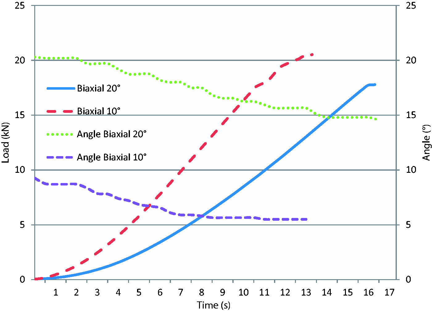
Tensile behaviour of triaxial braids
Tensile tests in longitudinal direction have been realized on triaxial braids. Figure 11 presents mechanical behaviours of two triaxial braids (with two different braiding angles). Like for biaxial braids we can distinguish a first non-linear part, where braids undergo geometric transition followed by a linear part where yarn properties govern the tensile behaviour of braids. The particularity of the behaviour is after the peak load. For small braiding angle, all the yarns (bias and axial yarns) are broken. However, for triaxial braids with a higher braiding angle we can show after a first unloading, a recovery of the load. We denote this behaviour as “double peak”. This phenomenon is not-existing for biaxial braids, due to the no axial yarns. Axial yarns are subjected to the load applied in their own direction; bias yarns, after the geometric transition, contribute to the stiffness of the braids, in this linear part. The first peak load is associated to the breaking point essentially of the axial yarns, consequently the load drops down. Afterwards, the force increases again in a similar manner of a simple biaxial braid, due to the bias yarns which preserve a good resistance mechanically. This zone is expressed by a second peak in the tensile behaviour until the failure. This singular behaviour has been described in case of bias extension tests of non-crimp fabric reinforcement [80] with a first zone associated with the tensile behaviour of the structure until the stitched thread failure followed by a second peak associated to pure shear of the reinforcement. The tensile behaviour of triaxial braids can be therefore summarized by a first non-linear zone, followed by a linear part, where we can compute a modulus (expressed in load units) until a first failure peak. In function of the initial braiding angle a second behaviour can be superimposed, by a second linear zone until a second breaking point.
Comparisons of tensile behaviour of two triaxial braids.
The evolution of the braiding angles, measured during tensile tests is superposed (Figure 12) to the tensile behaviour of a triaxial braid which has a double-peak behaviour as explained before.
Evolution of the braiding angle during the tensile test of triaxial braid.
This curve shows a quasi-linear decreasing of the braiding angle along the test. Comparatively to biaxial braids the evolution of the braiding angle does not show an asymptotic zone. After the failure of axial yarns we do not have a big variation of this braiding angle and consequently an influence on the reorganization of the bias yarns.
Comparison between biaxial and triaxial braids on the tensile behaviour
Previous sections have shown that the tensile behaviour of braids (biaxial and triaxial) could be divided into several zones. The comparison between these two kinds of braids (biaxial/triaxial) is conducted especially on the first linear part quantified by the values of the maximum load and slopes of linear parts (denoted modulus in load units). For triaxial braids which have a “double peak” tensile behaviour, values of modulus and maximum load are considered during the first linear part.
Figures 13 and 14 represent, respectively, the evolution of the maximum load and of the modulus in function of braiding angles of biaxial and triaxial braids. As explained before, for same parameters process, braiding angles are a little different between biaxial and triaxial braids. These angles are recalled on x-axis of these curves.
Comparison of maximum load of biaxial and triaxial braids. Comparison of modulus of biaxial and triaxial braids.

These curves show that the modulus and the maximum load decrease when the braiding angle increases and these evolutions are similar for triaxial or biaxial braids. The mechanical behaviour is highly dependent on braiding angle. These curves show that values for triaxial braids are always higher than biaxial braids, which is due to the additional axial yarns present in triaxial braids. Consequently triaxial braids have a higher stiffness than biaxial yarns. These results identified for braid confirm those obtained, and described in lot of publication [4,11,21,22,26,52,54], for composites elaborated from braided reinforcement.
Modelisation of the tensile behaviour of biaxial and triaxial braids
As mentioned in the introduction, many models are presented in literature to predict the mechanical behaviour of braided composites. According to the authors’ knowledge, the development of models concerning dry braided reinforcement is little studied. The aim of this section is to establish an analytical model to predict the tensile behaviour of dry biaxial and triaxial braids. These developments only concern, in these first works, the prediction of the longitudinal modulus of braids subjected to uniaxial tensile load.
In our application, all the yarns were subjected to the tensile load (Figure 15) applied in the longitudinal axis. We considered, in uniaxial tensile, in the global coordinate system (noted ei, ej) only the first component of load (F11), and strain ɛ11, computed from the global displacement u11. The local coordinate system associated to yarns defined by their angle is noted (e′i, e′j). This angle (α) is respectively equal to the braiding angle for bias yarns and 0° for axial yarns (not represented on Figure 14). The transformation between local and global coordinate system is intensively described in the literature concerning the establishment of models to predict elastic behaviour of braided composites [1,10,11,27–43] and based among others on the well-known Classical Laminate Theory (CLT).
Definition of local and global coordinates.
After transformation between the local coordinate system and the global coordinate system, the averaged stress–strain relation, expressed in the global coordinate system [31], for a yarn (α) can be resumed by equation (3).

Equation (3) developed for composite is expressed in terms of components of stress, strain and stiffness matrix. In relation with the experimental characterization presented before, with results in load vs. deformation, we used this relation, but in terms of loads (in N) function of strain, as given in equation (5).

The stiffness matrix is consequently associated to the rigidity matrix (in N), denoted [C]. From the relation (3), the rigidity in the global coordinate system for a yarn (α) ([C]
α
) can be computed from the rigidity ([C
α
loc
]) expressed in the local coordinate system by the relation (6):

Associated to uniaxial solicitation, only the first component of rigidity, Cα11, can be considered. In this model, we consider that yarns (bias and axial) are straight. Consequently the first component of the ([C
α
loc
]) matrix (in the local coordinate system) is the modulus (noted Eα) identified for a yarn and described in Table 1. From equations (4) and (6) we have the following relation (7).

From this equation, available for a yarn (α), we can deduce, with a sum on all yarns the relation connecting the axial load applied, F11 to the deformation ɛ11 measured in this axial direction. Thanks to the introduction of the modulus of the braid, expressed in N, and noted EBraid (8).

In the sum, it is necessary to dissociate bias yarns characterized by their angles and axial yarns oriented along the direction of load applied. The modulus can finally be expressed by equation (9).

With Nbias and Naxial, respectively, the number of bias and axial yarns.
The previous relation (9) is modified to take into account the ratio of fibres in braids. As classically used in laminate theory (CLT), we introduce a coefficient computed with the ratio between the mass of yarns (present in braids), noted Myarns and the mass of braids MBraid. Equation (9) is consequently replaced by the following equation (10).

Figures 16 and 17 show comparisons between experimental values of modulus and those computed by analytical relation (10), respectively, for biaxial and triaxial braids. We can conclude that the modulus computed is close to the experimental values.
Comparison between measured and theoretical modulus for biaxial braids. Comparison between measured and theoretical modulus for triaxial braids.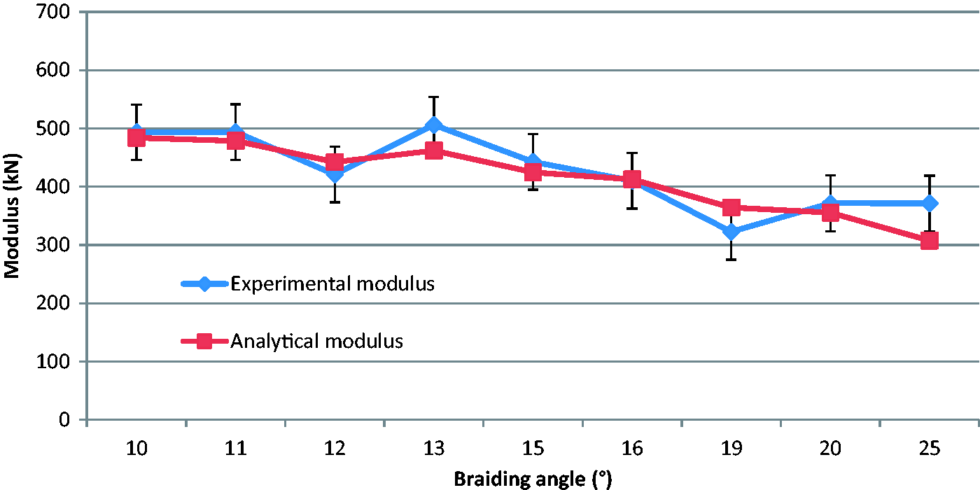

Conclusions
In this paper, biaxial and triaxial braids have been manufactured on the braiding loom with different parameters and from the same raw material. The experimental approach has allowed the identification of structural parameters as the braiding angle or the linear mass of these products in function of these process parameters. The evolution of the braiding angle in function of the production speed has been shown and can be predicted by analytical model, as described in several publications. Associated to the experimental measures of the linear mass, an analytical model taking into account the yarn crimp has been proposed. Mechanical characterization in the tensile behaviour of braids was conducted. The behaviour analysis has been associated with the braiding angle monitoring during the test. The specific behaviour of triaxial braids which present a double peak for higher braiding angle has been shown. These two points (a measure of the braiding angle during tensile test and identification of a double peak behaviour in tensile) have not been described in previous works. Comparisons conducted on the tensile behaviours between biaxial and triaxial braids elaborated with similar parameters process have been presented. The evolution of the modulus and the maximum load in function of the braiding angle was analysed. From numerous works on mechanical models predicting elastic constant of braided composite, a first model concerning the prediction of the modulus of braids has been defined. In future works this experimental approach will be completed with the manufacturing of braids with larger angles. The modification of the number of yarns, which is considered as constant, but also a comparison of tensile behaviour of braids manufactured with other raw material near of spectra used in this study. The definition of refined models characterizing the tensile behaviour of dry braids not only in modulus, but also in maximum load, strain will be also the subject of future development.
Footnotes
Declaration of Conflicting Interests
The author(s) declared no potential conflicts of interest with respect to the research, authorship, and/or publication of this article.
Funding
The author(s) disclosed receipt of the following financial support for the research, authorship, and/or publication of this article: the French state and the Nord Pas de Calais Region.