
Abstract
Structural parameters of fabrics influence the mechanical behaviour of fabric-reinforced composites. Weft-knitted spacer fabrics have high energy absorption capacity. In this paper, low-velocity impact behavior of composites reinforced with weft-knitted spacer fabrics has been studied using energy-balance method. The effect of fabric geometry on the impact behavior of composites was investigated. A theoretical model was generated to predict the energy dissipated through the impact, considering the structural parameters of fabrics as reinforcement of composites. For this purpose, dissipated energies due to contact, membrane and bending deformation of fabrics, and buckling deformation of spacer yarns were considered. In order to evaluate the proposed model, weft-knitted spacer fabrics with two types of spacer yarn's orientation were used as reinforcement of composites. Low-velocity impact examinations were performed using the drop hammer testing machine. The results showed that the model has about 12 and 13% error in prediction of dissipated energies of different samples. Comparison between theoretical and experimental results confirms that the proposed model is capable to predict the impact behavior of weft-knitted spacer fabric-reinforced composites.
Introduction
The wide application of composites in the aerospace, automotive, marine industries, etc. shows the importance of impact behavior of fabric-reinforced composites. It is well known that the structure of fabrics as reinforcements affects the impact behavior of composites. In the last decades, fabrics have been increasingly used as reinforcement of composites due to their unique mechanical and physical properties. Three-dimensional (3D) fabrics improve the through-the-thickness properties of composites due to the presence of z-fibers. Since, the low-velocity impact behavior of composite plates is considerably related to their through-the-thickness properties, spacer fabrics as reinforcement can improve impact resistance due to the existence of yarns in normal direction to the plate. Spacer fabrics are a kind of 3D fabrics which are proposed to use as reinforcement of composites in different applications. They have been known as suitable structures for particular properties [1–10]. Compressibility [1–4,9], air permeability [1,2], energy absorption [5], thermal transfer [1,5], protective [6,7] impact compressive behavior [7,8] of spacer fabrics have received the attention of researchers over the recent years.
Low-velocity impact behavior of textile composites has been studied by many researchers [11–22]. Woven [11,15,17], weft-knitted [12,13,14,21] and warp-knitted [21,22] fabrics have been used as reinforcement to increase the resistance of composites to impact damage. Naik et al. [11] studied the low-velocity impact behavior of the woven fabric laminated composites using the modified Hertz law. They concluded that the woven-fabric laminates are more resistant to impact damage than the cross-ply UD laminates. It can be attributed to the yarn interlacing in the fabric structure. Since the impact damage is often a delamination failure, resistance of cross-ply UD laminates is poor due to the lack of through-the-thickness reinforcement. Pandita et al. [12] used weft-knitted fabrics to improve the impact properties of composites. They stated that the impact damage profile is related to the degree of anisotropy in their tensile properties. Fiber orientation in the knitted fabric leads to confine the impact damage to one region. For this reason, the knitted structures are preferred to the woven structures in impact applications. It has been shown that in some literature [14,15,17,22] 3D fabrics are superior to 2D fabrics due to through-the-thickness reinforcement to improve the impact properties of composites. Liu et al. [14] investigated the dynamic response of composites reinforced with 3D weft-knitted spacer fabrics, and found that there is no inter-laminar fracture for this kind of composites. The most important impact damage in traditional composites is delamination failure [12]. Therefore, it is expected that the impact resistance of composites reinforced by spacer fabrics is considerably increased due to the presence of spacer yarns. Chen et al. [22] performed the compression and impact test on the composites reinforced with warp-knitted spacer fabrics. Their finding indicated that the fabric structural parameters have strong influence on the compression and impact responses of 3D structure composites.
The effect of yarns interlacing in the structure of woven fabrics on the low-velocity impact properties of woven fabrics-reinforced composites has been investigated by researchers [23–25] which confirms that the weave pattern influences the impact behavior of composites.
Based on the previous researches [12,26,27], weft-knitted spacer fabrics are suitable structures to increase the impact resistance of fabric-reinforced composites owing to compressive properties, high energy absorption capability and through-the-thickness reinforcement. Regarding these properties of weft-knitted spacer fabrics, in the present work, it is tried to model the impact behavior of composites reinforced with weft-knitted spacer fabrics. The aim of this study is to investigate the effect of structural parameters of weft-knitted spacer fabrics on the impact behavior of fabric-reinforced composites by modeling the dissipated energies.
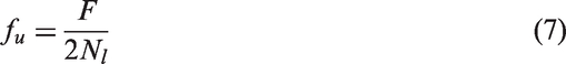
Theory of impact
Another approach for analyzing the impact dynamics is to consider the balance of energy in the system. The initial kinetic energy of the projectile is used to deform the structure during impact. Assuming that the structure behaves quasi-statically, when the structure reaches its maximum deflection, the velocity of the projectile becomes zero and all the initial kinetic energy has been used to deform the structure. The overall deformation of the structure usually involves bending, shear deformation, and for large deformations, membrane stiffening effects. Local deformations in the contact zone also are to be considered. For impacts that induce only small amounts of damage, the energy needed to create damage can be neglected.
The energy-balance (E-B) model is based on the principle of conservation of total energy [28]. According to the E-B model, the variation of the kinetic energy of the impacting mass is equated to the total internal dissipated energy (

The total energy of the deformations is considered as the sum of the energies due to contact, bending, shear, and membrane deformations [29]. Neglecting energy losses from material damping, surface friction, and higher mode vibrations, the E-B equation of the plate-impactor system is

Abrate [29] showed that


Impact behavior of composites reinforced with weft-knitted spacer fabrics
Weft-knitted spacer fabric is a 3D-knitted structure consisting of two separate knitted substrates which are joined together or kept apart by spacer yarns. Knitting is a method by which fabric is formed by loops of yarns in horizontal (course) or perpendicular (wale) directions. The fundamental unit is a loop or a stitch in the fabric structure. In weft knitting, loops are formed in a horizontal (course) direction. The stitches that run in columns along the length-wise direction of the fabric are known as “wales,” while the cross-wise rows of stitches are called “courses” (Figure 1).The main structural parameters of knitted fabrics are pattern (architecture), loop length, cpc and wpc which are the number of courses and wales per centimeter, respectively.
Wales and courses in weft-knitted fabrics.
Different architectures such as Plain, Rib, and Milano have been created using different yarns path in the fabric structures. As shown in Figure 2, in the 1 × 1 rib knit, the wale loops alternate between the front and back surface of the fabric.
1 × 1 rib structure.
As shown in Figure 3, weft-knitted spacer fabrics consist of top face, bottom face and spacer yarns. The pattern of top and bottom faces (layers) and orientation of spacer yarns are the structural parameters of weft-knitted spacer fabrics. It is clear that variation of structural parameters of reinforcement changes the mechanical properties of composites.
Different parts of weft-knitted spacer fabrics [14].
The deformations of top face, bottom face and spacer yarns of spacer fabrics are considered in composites plates which are subjected to impact force. Top and bottom faces undergo bending and membrane deformations, while spacer yarns undergo bending deformation. Therefore, the kinetic energy variation of the impactor is equal to the sum of the dissipated energies due to bending, transverse shear, and membrane deformation of faces and bending of spacer yarn at maximum deflection. Neglecting the shear deformation, equation (2) can be rewritten for spacer fabrics reinforced composites as below

The aforementioned energy terms should be calculated considering the structure of weft-knitted spacer fabrics as reinforcement of composites.
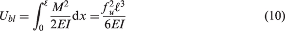
Bending energy of layers (
)
The bending energy of layer(s) is calculated using the corresponding force-deformation of loops as unit-cell of the layer. As shown in Figure 4, the contact zone is consisted of numerous loops. Since the spacer fabrics are composed of two layers and each layer contains a number of loops ( The contact zone.
The number of loops in the contact zone depends on the stitch density in the layer and the area of contact zone. The stitch density is obtained by multiplying the number of loops in the course and wale in the unit-cell. Therefore, the

Substituting equation (7) into equation (8)

According to Figure 5, the loops are bent in the structure of layers due to the impact force. Hence, the bending energy of the unit-cell ( Bending of a loop subjected to impact force.
Substituting the value of

Since each loop in the unit-cell consists of two straight portions of yarn as legs, then

The energy of loop should be multiplied by the number of loops in the contact area in order to calculate the bending energy of layers. Consequently, the bending energy of each layer becomes

Energy of membrane deformation of layers (
)
According to equation (5), it is necessary to define the boundary condition of samples for calculating the membrane energy of layers. Considering the immovable clamped boundary condition for plates, the

Substituting the value of

Bending energy of spacer yarns (
)
The bending energy of yarns depends on the number of spacer yarns in the contact zone. The number of spacer yarns in the unit-area is defined as psc (piles per square centimeter) The number of spacer yarns in the contact zone (

The force subjected to each spacer yarn is equal to

Substituting equation (16) into equation (17)

Since the spacer yarns have a deviation from straightness of their centroidal axis, they are considered as initially curved pin-ended struts. As shown in Figure 6, the lateral displacement at any point begins Initially curved strut.
In the structure of composites, the change of spacer yarn's curvature is due to the additional displacement, y, and the differential equation of bending is
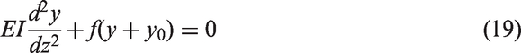
Assuming that


Considering the boundary conditions of simply supported beam, equation (21) for y reduces to

The energy dissipated due to buckling of a spacer yarns is given by

Deriving the value of

Solving equation (24) results

Putting the values of m and

Contact energy (
)
In order to find the contact energy, we need to calculate the contact stiffness (
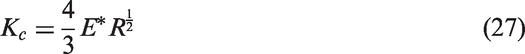


Substituting equations (28) and (29) into equation (27), the

Since the target is a plate, the

Therefore, the contact energy is calculated by putting equation (31) into equation (3)

Consequently, the total energy dissipated due to the impact on the composites reinforced with weft-knitted spacer fabric can be derived as follows

Experimental
Properties of glass yarns.

Details of weft-knitted spacer fabrics.

cpc: course per cm; wpc: wale per cm.
Using hand-layup method, composites were fabricated from made fabrics and Epoxy resin. The samples were cured at room temperature for seven days. The real photos and schematic of spacer yarn's orientations for different samples are shown in Figure 7.
Side view photos of spacer yarn orientation in prepared composites.
In order to measure the elastic modulus of composites, samples in dimension of 25 × 250 mm2 were provided according to the ASTM D3039.The tensile tests were carried out on an INSTRON tensile tester machine (Model 5566) under a nominal test speed of 10 mm/min. with gauge length of 200 mm. Low-velocity impact examinations were carried out using the drop hammer testing machine shown in Figure 8. In all tests, the projectile is a hemispherical steel tip with a diameter of 6.5 mm and the mass and contact velocity of the projectile are 2.712 kg and 2.56 m/s, respectively.
Low-velocity impact tester.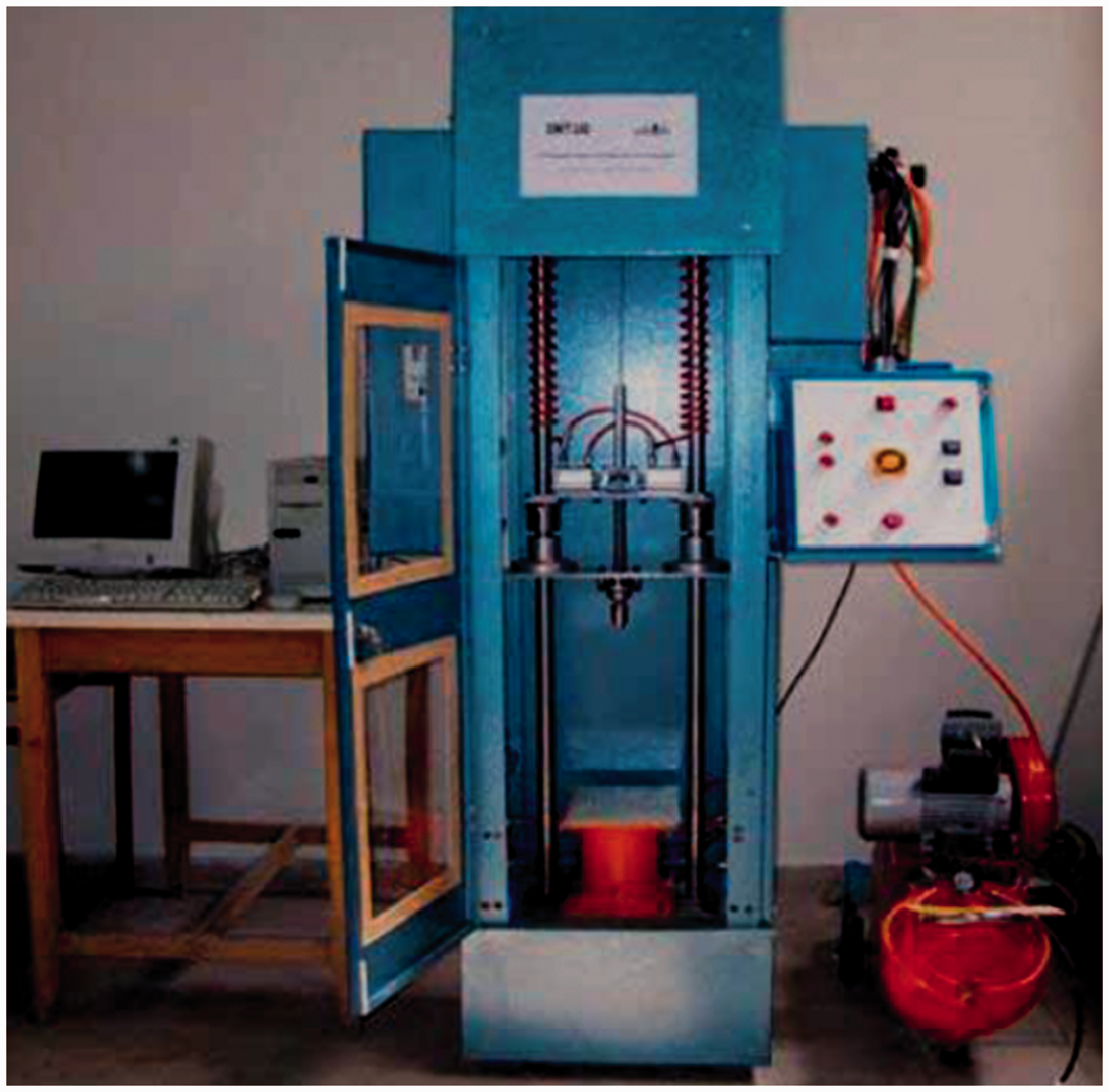
Figure 9 shows the results of the low-velocity impact test as acceleration–time graphs. As shown in Figure 9, the acceleration of impactor reaches to about 470 m/s2 for A1D2 and 400 m/s2 for A2D1 samples. Since the structure of top and bottom layers is similar, the difference between maximum acceleration of samples is attributed to their Acceleration–time plots of different samples.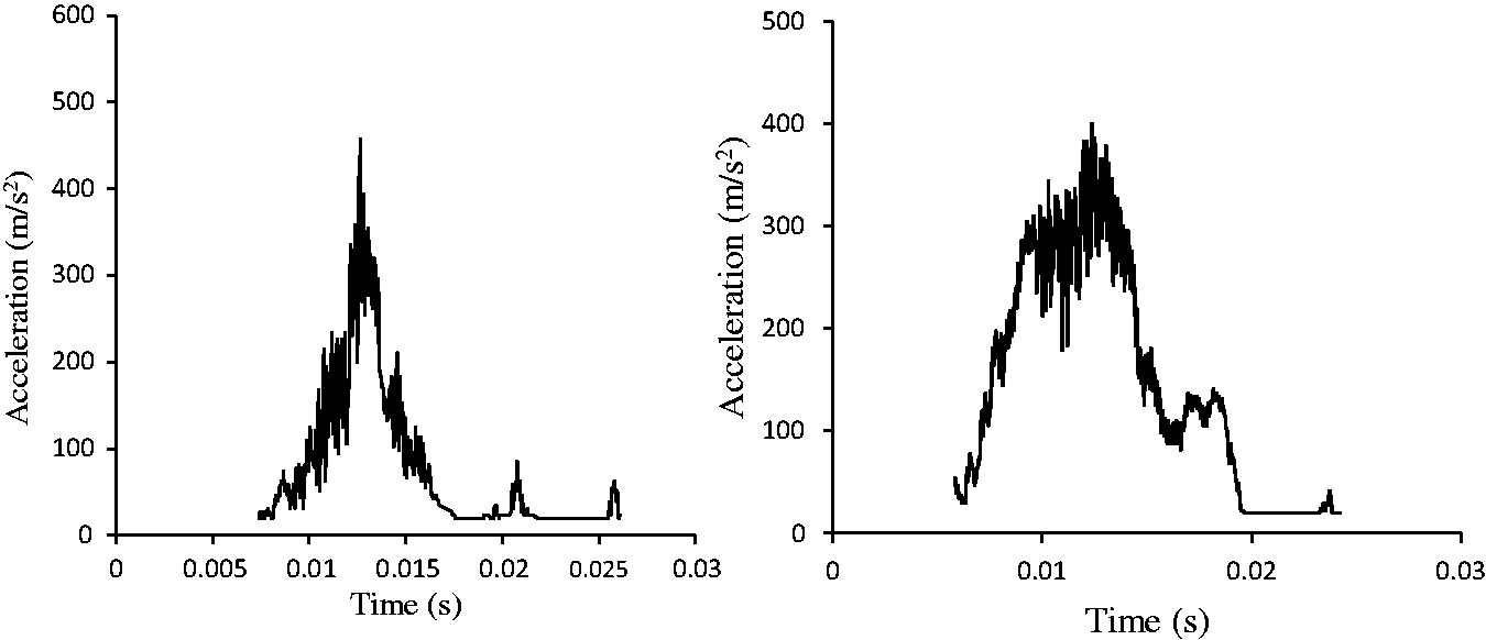
Using trapezoid rule of integration, the velocity–time and displacement–time graphs of impactor were plotted for both samples in Figures 10 and 11, respectively.
Velocity–time plots of different samples. Displacement–time plots of different samples.

Figure 10 shows the velocity versus time for both A1D2 and A2D1 samples. As shown, the graph of the A2D1 sample tends to zero, rapidly. As was pointed out, the spacer yarns have main role in dissipating the energy of impactor. Since the number of spacer yarns in the unit-area of A2D1 sample is as twice as that of A1D2, the trend of velocity reduction is more than A1D2 sample.
The displacement versus time diagram of impactor is shown in Figure 11. Indeed, it indicates the magnitude of impactor indentation. It is obvious that the less number of spacer causes more indentation of impactor. Therefore, the indentation of impactor in the case of A1D2 is more than that of A2D1.
Considering the mass and acceleration of impactor, the diagram of impact force–displacement for all cases is plotted in Figure 12. As shown in this figure, the maximum impact force is about 1000 N for both A1D2 and A2D1 samples, but the displacements at maximum force are different. The difference between diagram of impact force versus displacement of impactors for A1D2 and A2D1 will be discussed as difference between dissipated energies in the next section. The energy of impactor is calculated as the area under impact force–displacement diagram.
Force–displacement diagrams.
Validation of the model
Details of composites.
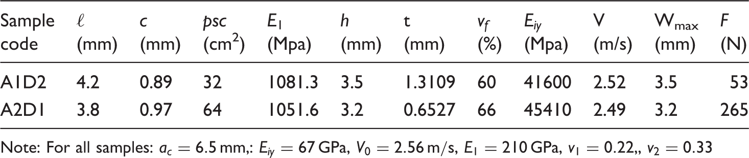
Note: For all samples:
psc: piles per square centimeter
Energy terms of composites.

The error percentage of theoretical and experimental values of energies was calculated as follows

The results showed that the model has about 12 and 13% error in prediction of dissipated energy of A1D2 and A2D1 samples, respectively. Taking into account the complexity of spacer fabric structures, it seems the model has an acceptable accuracy in prediction of low-velocity impact behavior of weft-knitted spacer reinforced composites. Although, validation of a model needs more experiments, but as a preliminary check, the accuracy of the model in prediction of impact behavior of produced samples is reasonable. A comprehensive experiment and FEM analysis is going to be the subject of further papers.
Conclusion
The impact behavior of composites depends on the structural parameters of weft-knitted spacer fabrics as their reinforcements. In addition to material properties, geometrical parameters of fabric influence the impact behavior of textile composites. To study the impact behavior of composites reinforced with weft-knitted fabrics, E-B method has been preferred. In order to use the E-B method, sum of the strain energies due to contact, bending and membrane deformation of fabrics and bending deformation of spacer yarns is considered. An analytical model was generated to predict the dissipated energies of composites reinforced with weft-knitted spacer fabrics under impact force. According to the generated model, parameters such as cpc, wpc, psc of fabrics and bending rigidity of yarns affected the value of total dissipated energy of composites during impact. To check the precision of the model, weft-knitted spacer glass fabrics and epoxy resin were used. Composites were fabricated using produced fabrics and Hand lay-up method. The low-velocity impact test was carried out on the provided samples using the drop hammer testing machine. The reasonable correlation between the theoretical and experimental results showed that the proposed model can adequately predict the impact behavior of weft-knitted spacer fabrics-reinforced composites.
Footnotes
Acknowledgements
The authors gratefully acknowledge the assistance and contributions from the Knitting Workshop of Textile engineering department in Amirkabir University of Technology for manufacturing the knitted fabrics.
Declaration of conflicting interests
The author(s) declared no potential conflicts of interest with respect to the research, authorship, and/or publication of this article.
Funding
The author(s) disclosed receipt of the following financial support for the research, authorship, and/or publication of this article: This paper has been funded by Amirkabir University of Technology.