
Abstract
Filter membranes with high efficiency and low energy consumption are gaining more attention owing to the increase in water pollution. To enhance the filtration performance, a novel spindle polyurethane (PU) / poly(vinyl alcoholco-ethylene) (PVA-co-PE) composite nanofiber membrane was prepared. It is the first time that the spindle composite nanofibers and nanofiber membranes are prepared based on the PU/PVA-co-PE/CAB (cellulose acetate butyrate) immiscible polymer blends. The effects of PU concentration on the morphology, size distribution, and hydrophilicity of PU/PVA-co-PE nanofiber membranes were analyzed. The pure PVA-co-PE nanofiber membrane and PU/PVA-co-PE composite nanofiber membranes were used to filtrate the nanoparticle suspension with scarlet pigments (50–300 nm). Due to the smaller pore size, looser structure, and larger porosity, the rejection rate and flux of spindle PU/PVA-co-PE composite nanofiber membranes are both higher than that of pure PVA-co-PE nanofiber membrane. When the basic weight of nanofiber layer is 6 g/m2, the rejection rate of all the PU/PVA-co-PE membranes are above 99%. This study provided a novel, facile, and high-throughput method to prepare spindle nanofiber membranes and indicated the advantage of spindle PU/PVA-co-PE composite nanofiber membranes in the application of water filtration.
Introduction
Water pollution has raised serious concern to mankind with increased industrialization and urbanization. To meet the increasing water consumption of future generations, water treatment technologies with properties of environmental friendly, low cost, and high efficiency are extremely desirable [1–3]. In the past few decades, many techniques have been developed for the wastewater treatment, such as coagulation, sedimentation, evaporation, absorption, ion exchange, electrolysis, membrane technologies, and so on [4–10]. Due to the advantages of high efficiency, easy operation, and space saving, membrane separation technologies like microfiltration (MF), ultrafiltration (UF), nanofiltration (NF), reverse osmosis (RO) have become the most attractive and promising methods for the wastewater treatment [1,11].
Based on the materials of construction, the separated membranes can be divided into three categories, including inorganic, organic, and hybrid membranes [1]. Among these materials, nanofiber membranes has gained much attention in recent years, due to their high specific surface areas, selectivity, porosity, and mechanical strength [12–14]. The most commonly used technology to prepare nanofiber is electrospinning. However, beaded/spindle fibers may be formed in the electrospinning process [15–19], which could affect the properties of nanofiber membrane. Therefore, lots of efforts have been thereby made to optimize the properties of nanofiber membranes [20–24].
However, high cost and low output of electrospinning limit its application, and so new methods should be developed to prepare nanofibers with controlled structure. Inspired by the in-situ fiber reinforced composites, a novel method was invented to prepare the thermoplastic nanofibers. Based on this method, various nanofibers including polyester, polyolefin, polyamide, and some copolymer have been prepared successfully in our previous studies [25–29]. Specially, poly(vinyl alcoholco-ethylene) (PVA-co-PE) and poly (trimethylene terephthalate) (PTT) nanofiber membranes were studied for the application of wastewater treatment [30–32]. However, the contradiction between filtration efficiency and water flux limited their performance and practical application.
In order to improve the filtration performance, the polyurethane (PU)/PVA-co-PE composite nanofiber membranes with spindle-like structures were prepared. It is the first time that the spindle composite nanofibers were prepared from the in-situ fiber reinforced composites by the melt extruding of immiscible PU/PVA-co-PE/CAB (cellulose acetate butyrate) polymer blends and subsequently removing the CAB matrix. The morphology, structure, hydrophilicity, pore size distribution, and filtration performance were characterized. Due to the formation of spindle-like structures, the filtration efficiency and water flux of the composite nanofiber membranes were enhanced compared with that of pure PVA-co-PE nanofiber membrane. This study provides a novel, facile, and high-throughput method to prepare spindle nanofiber membrane that has great potential for wastewater treatment.
Experiment
Materials
Cellulose acetate butyrate (CAB) powders (CAB 381-2.0), purchased from Acros Chemical (Pittsburg, PA), was used as the matrix phase. Poly(vinyl alcohol-co-ethylene) copolymer (PVA-co-PE, PE content 44%, Mn 78,459 g/mol, MW 426,588 g/mol, polydispersity 5.4), purchased from Sigma-Aldrich (Milwaukee, WI), and polyurethane (PU1185A), purchased from Bayer, were used as the dispersed phase. The basic weight of PET spunbond is 60 g/m2. Acetone (AR), purchased from Sinopharm chemical Reagent Co., Ltd, was used as the extractant to remove the CAB and part of the PU, which was not enwrapped by PVA-co-PE. Scarlet pigment nanoparticles suspension (PNPs) was chosen as a model contaminant for the filtration test.
Preparation of PU/PVA-co-PE composite nanofibers and nanofiber membrane
The spindle PU/PVA-co-PE nanofibers were prepared according to Figure 1. Firstly, all polymers including PU, PVA-co-PE, and CAB were dried and weighed according to Table 1 before mixing and melt blending. Then, the PU/PVA-co-PE/CAB mixtures were extruded by a twin-screw extruder (SHJ-18, D = 18 mm, L/D = 40) at 170–240 ℃, and the spin draw ratio (area of cross-section of extruded fiber to that of the die) was 5. As a result, the PU/PVA-co-PE/CAB composite fibers with the diameter of 1 mm were obtained. The PU/PVA-co-PE composite nanofibers were obtained by immersing the PU/PVA-co-PE/CAB composite fibers into acetone, and then centrifuging to remove CAB and part of the PU.
Preparation process of spindle PU/PVA-co-PE composite nanofibers. The weight proportion of all materials in the PU/PVA-co-PE/CAB blends.

To prepare nanofiber membrane, the PU/PVA-co-PE nanofiber bundles were dispersed into the mixture of water and alcohol by a high-speed blender. In this process, 7.5 wt% of polyacrylate was added into the solution to enhance the adhesion between the nanofiber layer and substrate. Following that, the PU/PVA-co-PE nanofiber suspension was sprayed onto the surface of PET spun-bond substrate. The nanofibrous membranes with 2, 3, 4, 5, 6 g/m2 of nanofibers on the substrate were fabricated successfully after drying. The whole preparation process was shown in Figure 2.
Preparation process and structure of the composite nanofiber membranes.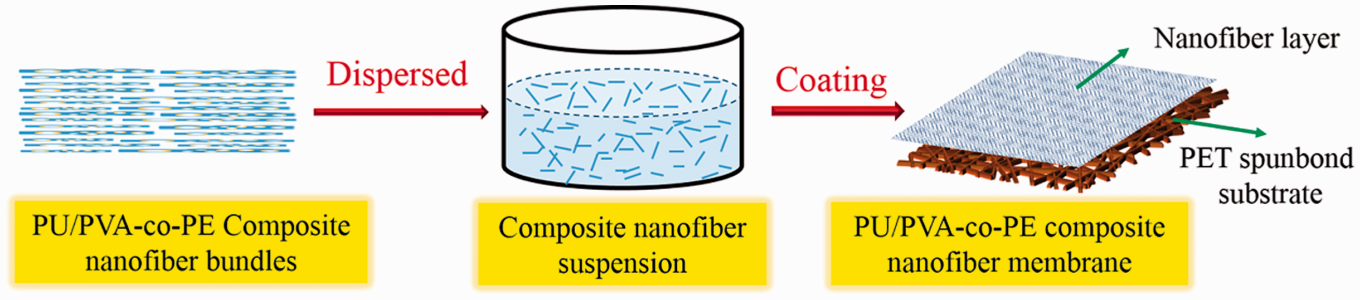
Morphology and structure of the nanofiber membranes
The morphologies of PVA-co-PE and PU/PVA-co-PE nanofibers were analyzed by the scanning electron microscopy (SEM, JEOL JSM-5510LV, Japan). The fiber diameter was measured by the image processing software (Image-Pro 5.0). The structure of PU/PVA-co-PE composite nanofibers with different PU concentration was tested by the FTIR-ATR (FTIR, Vertex70, Bruker). The mechanical properties of PET substrate and nanofiber membrane were tested with an Instron 6957 electronic tensile testing machine. The hydrophilicity of PU/PVA-co-PE nanofibers was evaluated by the contact angle goniometry (KRUSS DSA30S, KRUSS Co., Germany). The pore sizes and pore size distribution of the nanofiber membranes were analyzed by the capillary flow porometer (Model CFP-1500A, PMI Inc., USA).
Performance evaluation
The pure water fluxes of PU/PVA-co-PE nanofiber membranes with different PU concentration were tested by a cross-flow filtration (SF-SA Membrane Separation Technology Co.) at a preset pressure of 0.1 MPa. The flowing equation was used to calculate the pure water flux of nanofiber membrane.

In order to evaluate the filtration performance of PU/PVA-co-PE composite nanofiber membranes, the scarlet pigment nanoparticles (PNPs) were dispersed in the pure water with the concentration of 66.7 µL/L. The particle size distribution of PNPs was analyzed by using the Malvern laser particle size analyzer (Mastersizer 2000). The separation performance of nanofiber membrane to PNPs was carried out at a preset pressure of 0.1 MPa. The filtration efficiency was characterized by the reject rate (R) using the following equation

Results and discussion
Morphology and structure of the PU/PVA-co-PE nanofiber membranes
Figure 3 shows the SEM images of PU/PVA-co-PE composite nanofiber membranes with different PU concentrations. As shown in the figure, after the addition of high elastic PU into the polymer blends, the obtained PU/PVA-co-PE composite nanofibers become plumper compared with the pure PVA-co-PE nanofibers, forming a spindle-like structure. With the increase in PU concentration, the spindle-like structures become more obvious. The formation mechanism of nanofibers in the immiscible polymer blends has been analyzed in detail in our previously published works [33–35]. With a similar principle, the spindle-like structures could be explained by the embeddedness and shrinkage of PU in PVA-co-PE. Owing to the better miscibility of PU with PVA-co-PE, the majority of PU combined with PVA-co-PE in the melting process to form the PU/PVA-co-PE composite nanofibers. But only a minority of PU remained in the matrix phase of CAB and was removed subsequently with CAB by acetone.
SEM images of PU/PVA-co-PE composite nanofiber membranes with different PU concentrations of: (a) 0, (b) 10%, (c) 15%, (d) 25%, (e) 50%.
Figure 4 gives the average diameters of the PU/PVA-co-PE composite nanofibers. With the increase in PU concentration, the average diameter and size distribution of composite nanofibers become larger and wider. The high elasticity of PU leads to its easy shrinkability after extruding, thus resulting in the increase in the diameter of PU/PVA-co-PE composite nanofibers with the increase of PU concentration.
Average diameters of PU/PVA-co-PE composite nanofibers with the PU concentration of 0, 10%, 15%, 25%, 50%.
Figure 5 shows the FTIR spectrograms of pure PU, PVA-co-PE, and PU/PVA-co-PE composite nanofibers with different PU concentrations. For the pure PVA-co-PE nanofibers, as shown in Figure 5(a), the absorption peak at 3340 cm−1 corresponds to the stretching vibration of hydroxyl groups. The peaks at 2925 cm−1 and 2851 cm−1 represent the stretching vibrations of C–H bond. For pure PU, two peaks at 1738 cm−1, 1538 cm−1 and a shoulder at 1590 cm−1 are shown in the FTIR spectrum, which can be assigned to the stretching vibration of ester –C=O, amide C=N, and benzene C=C groups in PU. The peaks centered at 1227 cm−1 correspond to the C–N of urethane groups. The peak appearing at around 1072 cm−1 is attributed to the C–O–C stretching band [36–38]. It can be seen that the characteristic peaks of PU appears after the addition of PU and it becomes more obvious with the increase of PU concentration, demonstrating the formation of PU/PVA-co-PE composite nanofibers.
FTIR spectrograms of PU/PVA-co-PE composite nanofibers with different PU concentrations of: (a) 0, (b) 10%, (c) 15%, (d) 25%, (e) 50%, (f) 100%.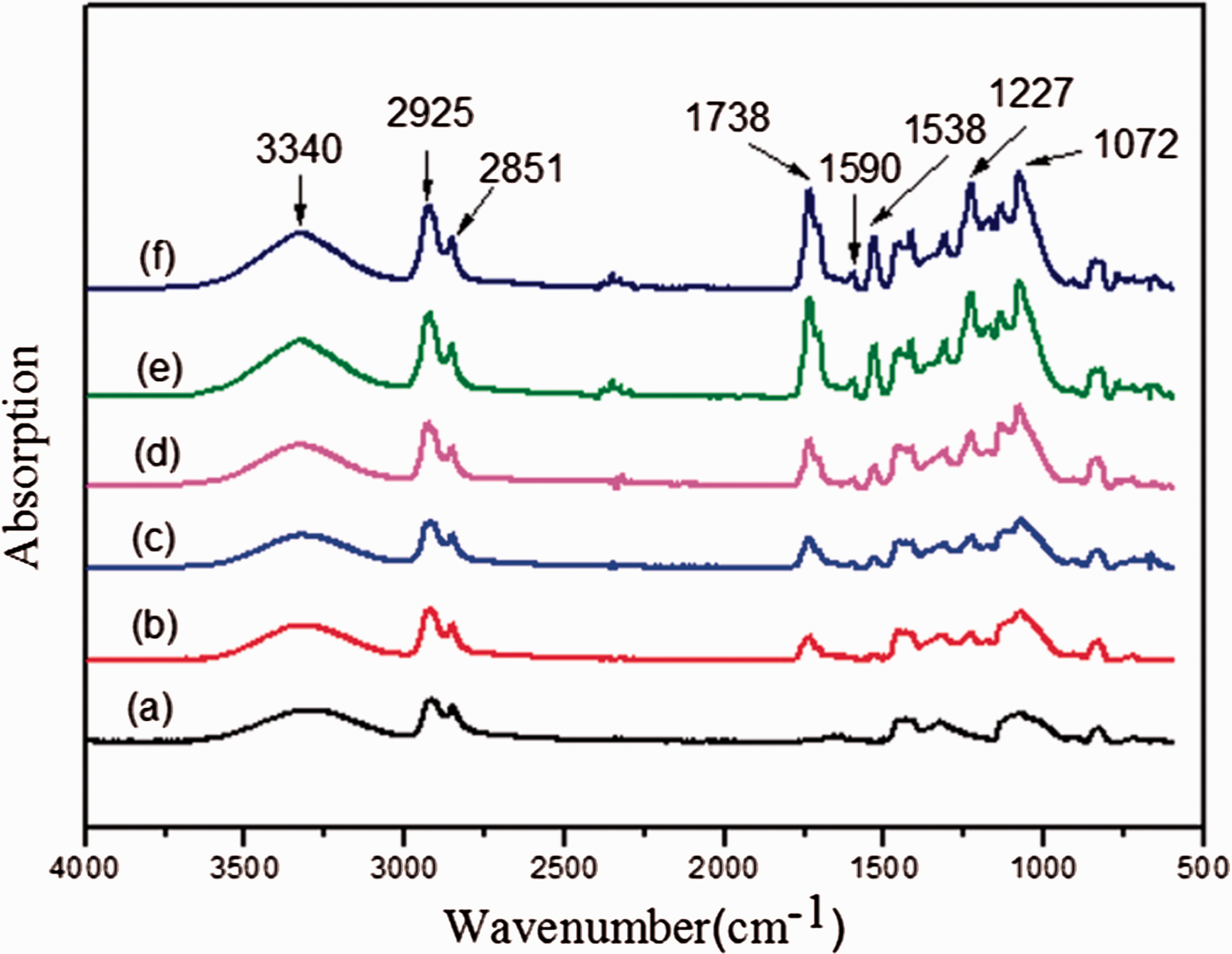
The hydrophilicity of nanofiber membranes with different PU concentrations are shown in Figure 6. With the increase in PU concentration, the hydrophilicity of PU/PVA-co-PE composite nanofiber membranes decreased. It is could be explained by the better hydrophilicity of PVA-co-PE compared with PU due to abundant hydroxyls groups are existing in the pure PVA-co-PE. Moreover, the increase in the average diameter of PU/PVA-co-PE nanofibers with the increase of PU concentration is also a reason for the decrease of hydrophilicity. There is a direct relationship between the contact angle and fiber diameter. The wettability increases with the decrease in the fiber diameter, due to the topography difference caused by the fiber diameter could influence the liquid–solid interface [39,40]. Besides, the roughness difference caused by the fiber diameter is also a reason influencing the contact angle. The greater roughness leads to a higher CA when the membrane is hydrophobic. Therefore, the increase in the average diameter leads to an increase in CA of PU/PVA-co-PE nanofiber membranes.
The hydrophilicity of PU/PVA-co-PE composite nanofiber membranes with different PU concentrations of: (a) 0, (b) 10%, (c) 15%, (d) 25%, (e) 50%.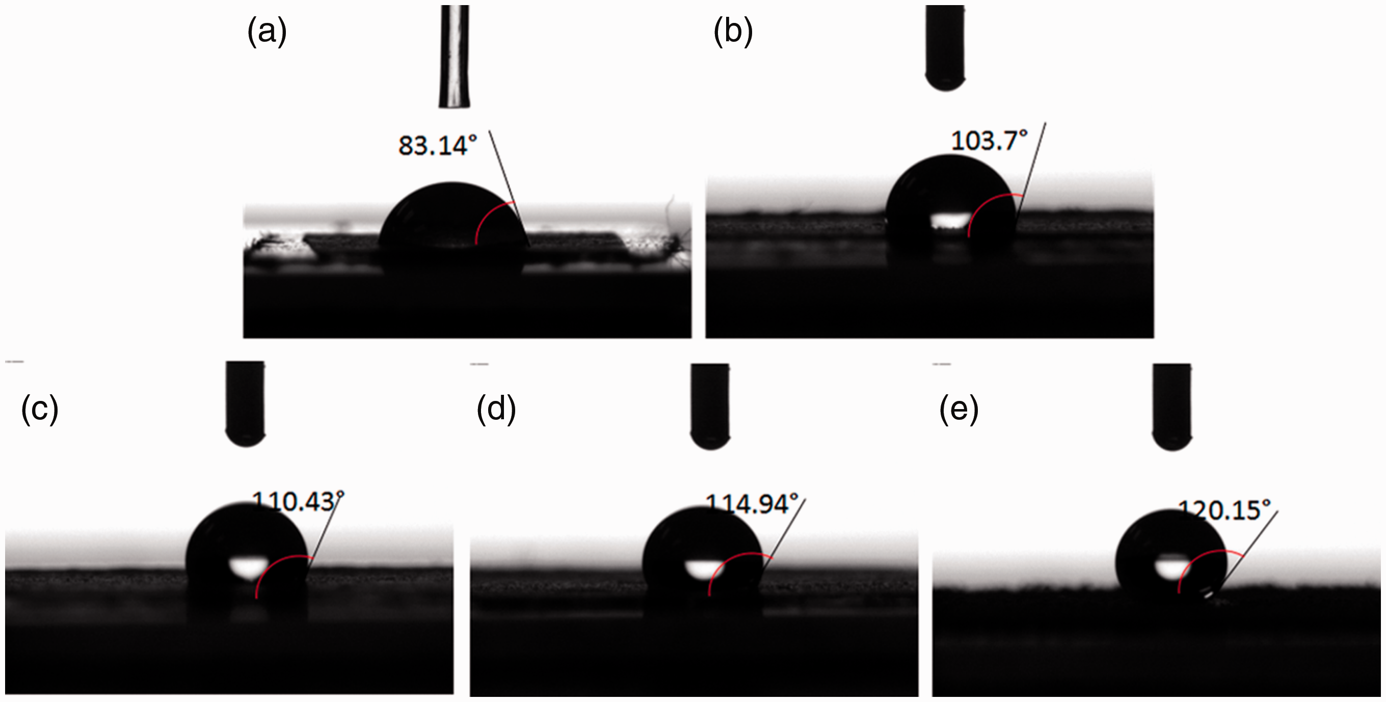
After coating the PU/PVA-co-PE composite nanofibers on the PET spunbund substrate, the average pore sizes were analyzed, as shown in Figure 7. The pore size distribution of composite nanofiber membrane is mainly determined by the morphology and size of nanofibers. In the case of 10% PU and 15% PU, the formation of spindle-like structure is the dominant factor. Because the spindles on the composite nanofibers blocked part of the pores, so the average pore sizes of PU/PVA-co-PE composite nanofiber membranes decreased with the increase of PU concentration and attained the smallest for 15% PU. When the loading of PU increased to 25% and 50%, the pore size began to increase with the increase in PU percentage as the increase of nanofiber diameter became the main factor. Anyhow, the pore sizes of all PU/PVA-co-PE composite nanofiber membranes are smaller than that of pure PVA-co-PE nanofiber membrane. Moreover, the PU/PVA-co-PE composite nanofibers became shorter and looser after the addition of PU, making it is easier to be dispersed into the solvent and forming the uniform nanofiber suspension. In contrast, the pure PVA-co-PE nanofibers were longer and compacter, which should be dispersed in the solvent by a high-speed mixture. Therefore, the better uniformity of PU/PVA-co-PE composite nanofiber membranes was also a reason for their smaller pore size distribution.
Average pore size of PU/PVA-co-PE composite nanofiber membranes with different PU concentrations of 0, 10%, 15%, 25%, 50%. The basic weight of nanofiber layer is 4 g/m2.
Filtration performance
Water flux is quite important for the filtering membrane, because it decides the production and economic effectiveness of membrane in the practical application. As shown in Figure 8, all the PU/PVA-co-PE membranes show better pure water fluxes compared with the pure PVA-co-PE nanofiber membrane. It is because the spindle composite nanofibers construct a membrane with looser structure and larger porosity, as shown in Figure 9. Besides, the water fluxes of PU/PVA-co-PE nanofiber membranes are relative to the pore size distribution. Larger pore size leads to larger channels for water flow and less membrane resistance, so the water flux increases with the increase of pore size distribution. That is why the flux of nanofiber membrane with 15% PU is the smallest and the water flux is the largest when the PU percentage is 50%. Moreover, the water fluxes decrease obviously with the increase in the basic weight of nanofiber layer because of the formation of a compacter nanofiber layer on the substrate. In order to confirm the appropriate PU concentration and nanofiber thickness, the filtration efficiencies of all the nanofiber membranes were analyzed.
Pure water fluxes of PU/PVA-co-PE composite nanofiber membranes with different PU concentrations at 0.1 MPa. Structure comparison of the PVA-co-PE nanofiber membrane and spindle PU/PVA-co-PE composite nanofiber membrane.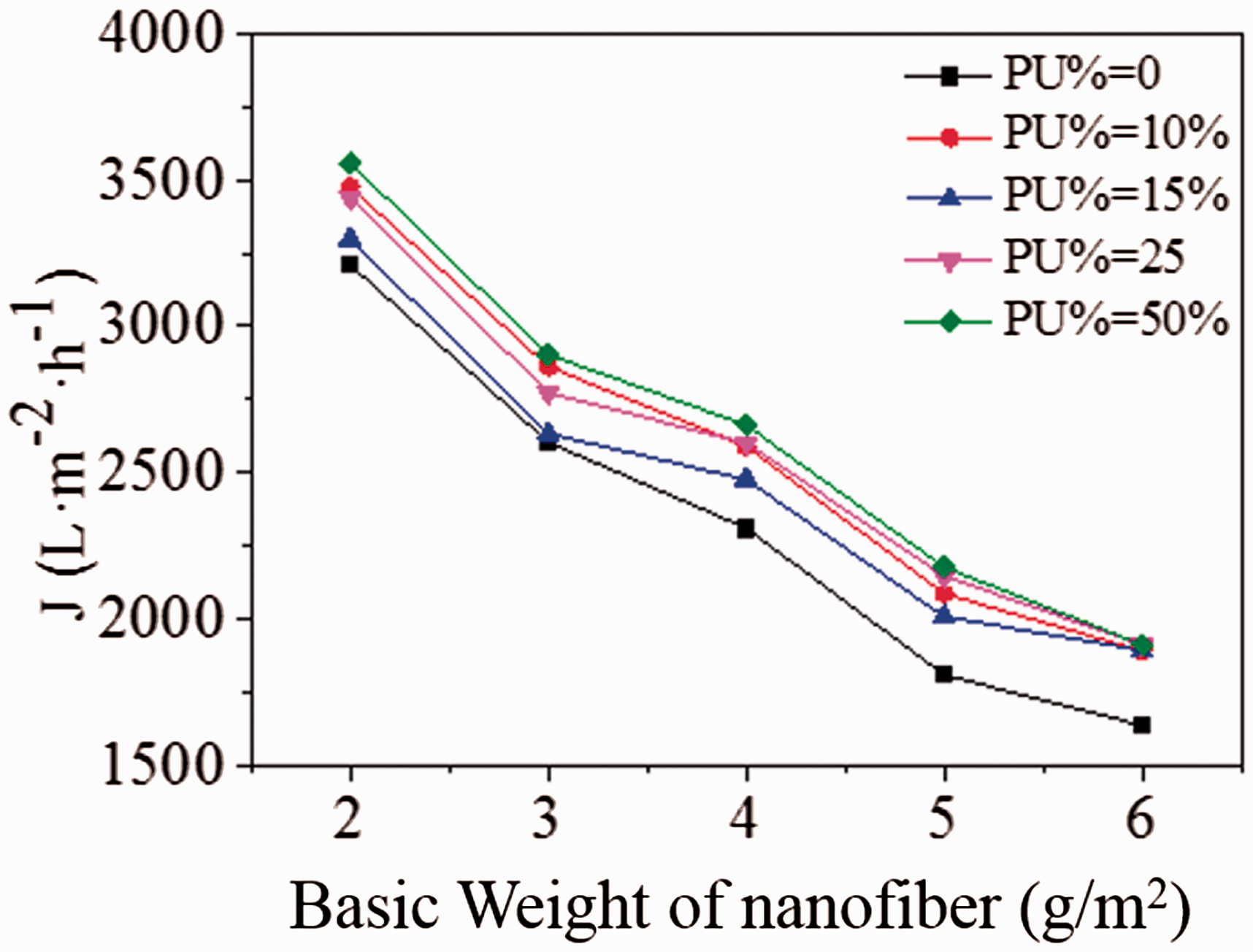

To evaluate the filtration performance of all the nanofibrous membranes, the PNPs suspension is selected as the contaminant for the rejection rate test. As shown in Figure 10(a), the average size of PNPs is 123 nm. As the particle sizes of PNPs are little smaller than the pore sizes of nanofiber membranes and there is no chemical adsorption between the nanofiber membrane and pigment, the filtration theory for this study could be explained as interception. Obviously, the PNPs were intercepted on the surface of nanofiber membrane after the filtration, as shown in Figure 10(c) in comparison to Figure 10(b). The stress–strain curves of PET substrate and nanofiber composite membrane in Figure10(d) indicates that the composite nanofiber membrane is strong enough to endure a long time application. The rejection rate could be calculated by the UV-Vis absorption spectrogram based on the adsorption peak at 572 nm, as shown in Figure 10(e) and (f). The rejection rates of all PU/PVA-co-PE composite nanofiber membranes were higher than that of pure PVA-co-PE nanofiber membrane. The better filtration efficiency of spindle PU/PVA-co-PE composite nanofiber membrane is explained in Figure 11. For the normal and spindle-like nanofibers with the same diameter, the slightly expanded spindles existing on the nanofibers enable the membrane to possess a smaller pore size, thus leading to a better filtration efficiency. When the PU percentage is 15%, the rejection rate of PU/PVA-co-PE composite membrane is the best because of its smallest pore size distribution. Moreover, the rejection rate increases with the increase in the basic weight of nanofiber layer. When the basic weight is smaller than 4 g/m2, the rejection rate is smaller due to the incomplete nanofiber layer on the substrate. The rejection rate becomes higher when the basic weight is higher than 4 g/m2, because of the formation of a compact and whole nanofiber layer. When the basic weight of nanofiber is 6 g/m2, the rejection rates of all the PU/PVA-co-PE membrane are above 99%. To ensure a better filtration performance including the flux and rejection rate, we chose the PU/PVA-co-PE nanofiber membrane with PU concentration of 15% and basic weight of 4 g/m2 for the durability test.
(a) Particle size distribution of PNPs; (b) and (c) morphology of nanofiber membranes before and after the filtration test; (d) the stress–strain curves of PET substrate and composite nanofiber membrane; (e) UV-Vis absorption spectrograms of PNPs suspension before and after being filtrated by the PU/PVA-co-PE composite nanofiber membrane (PU% = 15%); (f) rejection rate of PU/PVA-co-PE nanofiber membranes with different basic weight of nanofiber layer and PU concentration. Filtration mechanism of the pure PVA-co-PE nanofiber membrane and spindle PU/PVA-co-PE composite nanofiber membrane.
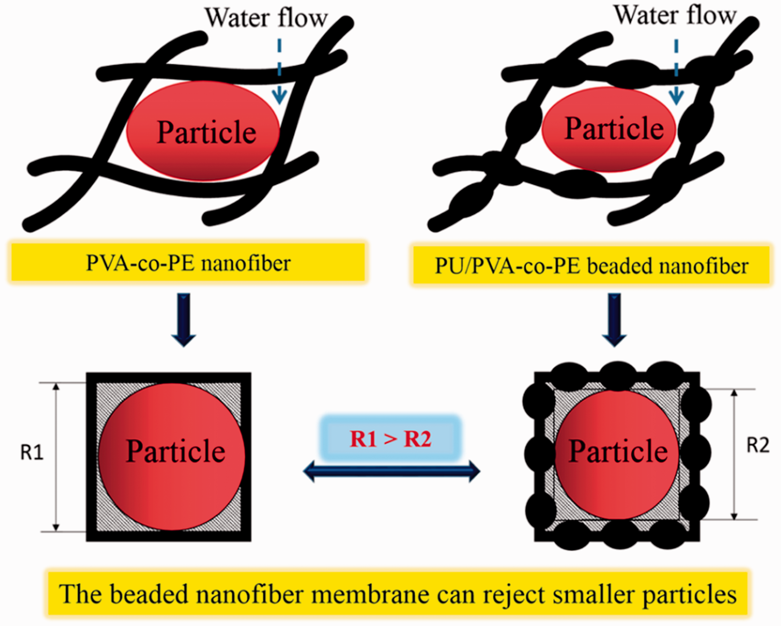
Figure 12 shows the time dependence of pure water fluxes and PNPs suspension fluxes, indicating the efficiency and durability of nanofiber membranes. As shown in Figure 12(a), the water flux decreased in the initial 20 min, and then attained an equilibrium. All the nanofiber membranes exhibited water fluxes of 2000 L/m2·h above after 60 min filtration. After the addition of PU, the water flux of PU/PVA-co-PE composite nanofiber membranes increased compared with that of pure PVA-co-PE nanofiber membrane. In Figure 12(b), the nanofiber membranes were used to filtrate the PNPs suspension for 600 min. At the beginning of filtration, the flux decreased remarkably due to the pore blocking and the formation of PNPs cake layer on the surface of nanofiber membrane. After 30 min, the upward tendency of the membrane resistance approached an internal equilibrium, and then the fluxes became stable in the later filtration process. Similarly, the fluxes of PNPs suspension became larger after the addition of PU, indicating the better efficiency and durability of PU/PVA-co-PE composite nanofiber membranes.
Time dependence of: (a) pure water fluxes and (b) PNPs suspension fluxes for PU/PVA-co-PE composite nanofiber membranes with different percentages of PU.
Conclusion
The spindle PU/PVA-co-PE composite nanofiber membranes were prepared by a new method of in-situ fiber reinforced composites in this study and were used to filtrate the microsize particles in water. After the addition of PU in the polymer blends, the obtained PU/PVA-co-PE composite nanofibers became plumper, forming a spindle-like structure. With the increase in the PU concentration, the spindle-like structure on the nanofibers was more obvious. The slightly expanded spindles on the nanofibers lead to a smaller pore size for the membrane, thus enhancing the filtration performance. When the PU concentration was 15%, the PU/PVA-co-PE composite nanofiber membrane got the best rejection rate because of its smallest pore size. Meanwhile, the water fluxes of PU/PVA-co-PE composite nanofiber membranes were also higher than that of pure PVA-co-PE nanofiber membrane due to the looser structure and larger porosity. All of the results demonstrated the advantage of spindle PU/PVA-co-PE composite nanofibers in the application of water treatment.
Footnotes
Declaration of conflicting interests
The author(s) declared no potential conflicts of interest with respect to the research, authorship, and/or publication of this article.
Funding
The author(s) disclosed receipt of the following financial support for the research, authorship, and/or publication of this article: This study was supported by the National Key Research and Development Program of China (2016YFC0206101, 2016YFC0400504), Science and Technology Innovation Major Projects of Hubei Province (2016AAA019), National Science Foundation of Hubei Province (2016CFA076), Excellent Innovative Team of Young Researchers from Hubei Provincial Department of Education (T201408), and Creative Research Group of Hubei province (2015CFA028). We also thank “Wuhan Engineering Technology Research Center for Advanced Fibers” providing partial support for materials processing.