
Abstract
The importance of the nanofiber webs increases rapidly due to their highly porous structure, narrow pore size, and distribution; specific surface area and compatibility with inorganics. Electrospinning has been introduced as one of the most efficient technique for the fabrication of polymeric nanofibers due to its ability to fabricate nanostructures with unique properties such as a high surface area and porosity. The process and the operating parameters affect the nanofiber fabrication and the application of nanofibers in various fields, such as sensors, tissue engineering, wound dressing, protective clothes, filtration, desalination, and distillation. In this review, a comprehensive study is presented on the parameters of electrospinning system including applications. More emphasis is given to the application of nanofibers in membrane distillation (MD). The research developments and the current situation of the nanofiber webs in MD are also discussed.
Introduction
The engineered materials have been gained huge interest during the last decades due to improvement in technology and increase in demands. Many of the applications commonly require mechanically strong, corrosion resistance, lightweight, long-lasting, recyclable, easy to process, easy to handle, reproductive, and low price materials. Polymeric materials can fulfill the general demands for upper qualified applications. Currently, polymers are used everywhere in our daily life. Beside inorganic materials, polymers are actively used in nanotechnology. Nanotechnology means the science and technology takes place in nanometer dimensions. The biggest importance of the nanotechnology is their aspect ratio which is related with the large surface area to volume ratios and their quantum effects. It is not simple to import polymer science into nanotechnology.
One of the promising areas of nanofiber is that mainly polymeric materials are used. During the process, the polymeric solution/melt is extruded, drawn or split into very fine fibers using external chemical or physical methods such as an electrical field, drawing force, splitting into smaller pieces. There have been reported various methods in the literature for the preparation of nanofibers. Some of these methods are drawing, 1 electrospinning,2–5 meltblowing, 6 template synthesis,7,8 self-assembly,9,10 phase separation, 11 island in the sea, 12 force spinning,13,14 and bubble electrospinning. 15 Among all, electrospinning is the most commonly and mostly used method for production of nano-fibers. Electrospinning is so far the most used method for industrial production. More than half of the research arti-cles which related to nanofiber are produced by electro-spinning methods. 14
Electrospinning
Electrospinning basically requires a polymeric solution/ melt and an electrical field. In most of the electrospinning setup designs, there is a feeding unit which transports the polymeric solution/melt into the electrical field. There is a high-voltage supplier connected to the feed solution. On the opposite side of the feed solution, there is a metallic collector which can be oppositely charged or grounded. The electrical field is generated between the feed solution and the opposite side collector. If the generated electrical field overcomes the surface tension of the polymeric solution, Taylor’s cone 16 is observed; then, the solution starts to move toward to collector and under the force and instability initiates, the whipping or splitting of the polymeric solution will be observed. Dur-ing the whipping, the drawing continues until the polymeric solution contacts to the collector. Whipping instability causes bending and stretching of the jet. 17 On the other hand, if there is splitting, the polymeric solution splits into multiple filaments. The solvent starts to evaporate during whipping or splitting. The mechanism of the bending instability was explained by Yarin et al. 18 They calculate the shape of the envelope cone which surrounds the bending loops of the jet during the whipping of polymeric solution. The image of whipping and splitting is shown in Figure 1.

The whipping and splitting behavior of polymeric jet under the electrostatic field.
Electrospinning methods can be grouped into two as needle and needleless electrospinning. In general, single nozzle or needle system is used in electrospinning system for research goal. In single needle electrospinning system, the polymeric solution is stored inside a needle which is connected to a high-voltage supplier. A syringe pump is used for the feeding of the solution to needle tip as shown in Figure 2. There are various parameters in needle system which has an effective role in the morphology and productivity of nanofibers. These parameters can be categorized into two groups as system and process parameters. The system parameters include the properties of a polymeric solution such as concentration, viscosity, conductivity, surface tension, permittivity, and the molecular weight of the polymer. On the other hand, process parameters are related to devices setup and environment such as applied voltage, the distance between electrodes (tip to collector), the fed rate of solution, the diameter of the needle tip, and ambient conditions. Each parameter affects the surface morphology of the nanofibers. Deitzel et al. 19 showed that defect-free polyethylene oxide (PEO)/water nanofibers were produced at 5.5 kV. When the voltage increased to 9 kV, bead structures took place. The result showed that the applied voltage had a significant effect on the shape of the droplet and beads-free structure. They also found that the PEO solution concentration has a significant effect on the final size and distribution of particles. PEO at a molecular weight 400,000 g/mol, concentrations in the range of 4–10 wt% produced fibers. When the concentration decreased, the fibers have an irregular shape; droplets with fibers were observed during electrospinning. For solutions with a concentration of 15 wt% or more, the viscosity of the PEO solutions became difficult to spin due to force through the syringe needle of the apparatus, and the droplet at the end of the capillary stretched into a thick diameter around 0.5mm. Resultant fibers have a regular, cylindrical morphology and on average have a larger and more uniform diameter. In most cases, an increase in the concentration and the applied voltage results in an increased fiber diameter. Similar results were found in another works.20–22 Matabola and Moutloali 23 used sodium chloride (NaCl) salt as an additive to polyvinylidene fluoride (PVDF)/dimethyl acetamide solution to improve surface morphology of the nanofibers. Increase in NaCl content yields to increase in fiber diameter. In the previous work, the lithium chloride (LiCl) and tetraethylene ammonium bromide (TEAB) salts were into PEO/water solution in various ratios.24,25 Adding salt increases the conductivity while decreasing the spinnability and productivity of the nanofibers. It was explained that adding salt to PEO increases the conductivity of the solution which shows a behavior as a conductor. As a result, the solution loses the characteristic of a leaky model which leads to the loss of ability to create Taylor cones.26,27 The same behavior was observed with adding a various concentration of sodium hydroxide (NaOH) salt into polyvinyl alcohol (PVA)/water solution. 28 On the contrary, it was found that adding TEAB and LiCl salts into polyurethane (PUR)/dimethylformamide increased the number of jets which results in higher productivity.25,29–31 Casper et al. 32 prepared polystyrene (PS)/tetrahydrofuran nanofibers in different molecular weight of PS (31,600, 171,000, 190,000, and 560,000 g/mol) at various humidity. The resultant fibers showed that both humidity and the molecular weight affect the surface of electrospun PS. Larger fiber diameter and less uniform pore-shaped nanofibers were produced by increas-ing the molecular weight. Moreover, increasing humidity causes an increase in the diameter, shape, and distribution of the pores. Smooth nanofibers were produced at humidity less than 25%, while pore structures were observed at 30% relative humidity. In another work, various molecular weight polyamide 66 nanofibers were electrospun. Resultant fibers showed that increasing the molecular weight causes an increase in fiber diameter. It was suggested that a critical low molecular weight was necessary for electrospinning. 33 The molecular weight does not only have an effect on fiber diameter but also on the mechanical strength of the fiber. An increase in molecular weight increases the tensile strength and modulus of the nanofiber mat. 34

Diagram of needle electrospinning system.
Using a needle and needle-free electrospinning system, various polymeric solutions were used to produce nanofibers in various applications. Some examples of them are shown in Tables 1 and 2.
Electrospun nanofibers and their application using needle electrospinning system.

SF: silk fibroin; HA: hydroxyapatite; PANI: polyaniline; PVA: polyvinyl alcohol; PCL: polycaprolactone; PLA: poly(lactic acid); FHA: fluorhydroxyapatite; PA6: polyamide 6; CPI: carbonized polyimide; PAA: poly(- acrylic acid); PVDF: polyvinylidene fluoride; PAN: polyacrylonitrile; PSU: polysulfone; PEO: polyethylene oxide; PUR: polyurethane; PA66: polyamide 66; MnO: manganese monoxide; Ag: silver; Au: gold; TiO2: titanium dioxide; CO: carbon monoxide.
Electrospun nanofibers and application using needle-free electrospinning system.

CS: chitosan; PEO: polyethylene oxide; PVA: polyvinyl alcohol; PUR: poly-urethane; PCL: polycaprolactone; PA6: polyamide 6; PVDF: polyvinylidene fluoride; PAN: polyacrylonitrile.
Single needle electrospinning system is not enough to fulfill the productivity. Various electrospinning systems have already been designed to improve the productivity of the nanofibers. These methods include bubble electrospinning,96,97 two-layer fluid electrospinning, 98 multi-jet electrospinning, 99 conical wire coil electrospinning, 100 edge plate electrospinning, 101 rotating roller electrospin-ning,102,103 wire electrospinning,104,105 and so on. Compared to needle electrospinning system, needle-free electrospinning system has advantages. For instance, the clogging of needles is a problem and there has to be a proper distance between needles. Otherwise, the electrical fields around needle affect each other and stop the spinning. Both roller and wire electrospinning system are currently used in industrial scale under the trade name Nanospider with a different generation. The first generation of Nanospider is a rotating roller electrospinning patented by Jirsak et al. 102 as shown in Figure 3.
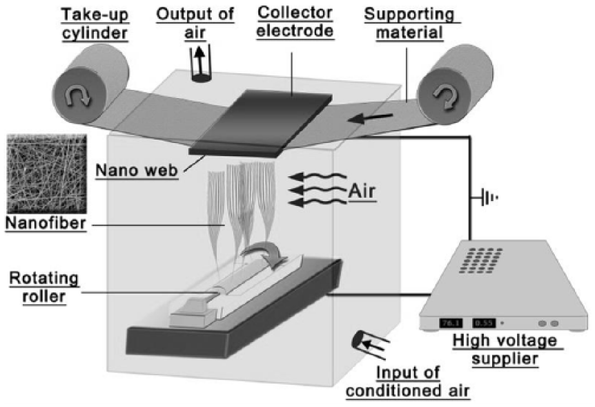
Diagram of roller electrospinning system.
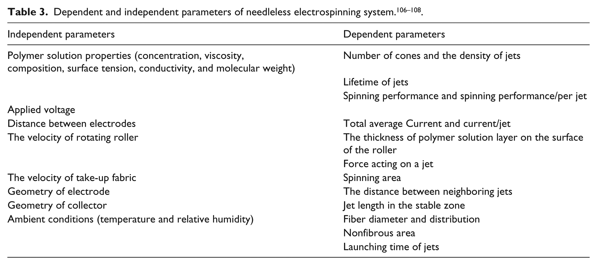
In the principle of roller electrospinning system, there is rotating roller immersed in a polymer solution tank which is connected to a high-voltage supplier. The polymer solution is fed to the surface of the roller via rotation. Spinning starts on the surface of the roller. The spinning is done in a closed chamber to maintain ambient conditions and keep it stabilized during the process. Both the system and the process parameters play a big role in the final product. The process parameters of the roller electrospinning system are quite different compared to needle electrospinning due to a different setup. In literature by Yalcinkaya et al.,106–108 the parameters of needle-free electrospinning system are classified as “dependent and independent parameters” as shown in Table 3. On the other hand, the parameters for the wire electrospinning system are still not investigated.
The working principle of the wire electrospinning is different than roller electrospinning. The polymeric solution is placed into a closed tank which is the feeding unit. In the middle of the solution tank, there is a wire passing along to spinning area. The wire is connected to high-voltage supplier. The solution tank is moving back and forth and the solution is feeding on the wire. The second wire electrode is placed on the upward that generally has the opposite charge to the downward wire electrode or is grounded. A conveyor supporting material is placed in front of the upward electrode to collect the nanofibers. 104 Figure 4 shows the schematic diagram of wire electrospinning system.
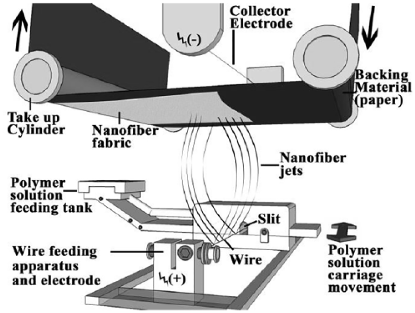
Schematic diagram of wire electrospinning system.
The advantages of the wire system compared to the roller are that solution is in a closed tank and the surface of the wire electrode is narrower which increases the electrical field intensity around the wire. Various polymeric solutions are possible to electrospun in industrial scale. The main advantages of nanofibers are their specific surface area, high aspect ratio, extreme porous structure, and small pore size. Nanofibers have shown unique characteristics and enormous application potential. One of the successful application areas of nanofiber is water purification. Nanofiber membranes in the membrane distillation (MD) application are discussed in the next section.
Nanofibers in water purification
Membrane distillation
MD is a water separation process which is one of the emerging desalination technologies for the production of fresh water. Compared to other membrane systems, MD has several advantages, such as higher salt rejection, lower operating temperature than conventional distillation processes, low energy consumption (when the alternative energy source is used), hence there are lower operating pressure requirement less requirements of membrane mechanical properties. 109
The principle is that vapor transport across the hydro-phobic microporous membrane driven by the vapor pressure gradient across the membrane due to a temperature gradient. The volatile solvent evaporates through the membrane via diffusion and/or convection. The vapor is transported to the compartment with low vapor pressure where they are condensed in the cold liquid/vapor phase (Figure 5).

Illustration of membrane distillation process.
MD technology is applicable for many application areas such as wastewater remediation, sea water distillation, and separation of volatile liquids. Even though the rejection of MD membranes is 100%, this technology has not found a place in the industrial stage. The reason is due to low flux and permeability of the membranes, possible pores wetting and water loss, energy consumption, and machinery cost. Besides disadvantages, there are several advantages of MD, such as full rejection, lower pressure-driven separation process as a result of low requirement for mechanical properties and low operating temperature. There are several configurations of MD unit reported in the literature by Khayet and Matsuura 110 and Wang and Chung, 111 such as direct contact membrane distillation (DCMD), air gap membrane distillation, sweeping gas membrane distillation (SGMD), and vacuum membranedistillation (VMD). The membrane is the most important part of the MD process (Figure 6).

Some of MD process configurations. (a) DCMD, (b) AGMD, (c) SGMD, and (d) VMD (originate from 110 ). MD: membrane distillation; DCMD: direct contact membrane distillation. AGMD: air gap membrane distillation; SGMD: sweeping gas membrane distillation; VMD: vacuum membrane distillation.
In DCMD, a membrane is placed between permeate and a hotter feed solution. It has to have a temperature gradient between feed and permeate. The membrane is in contact both feed and permeates side. A magnetic stirrer or circulating pumps are used to circulate feed and permeate solu-tion to the membrane surfaces. As a result of heat difference on both sides of the membrane, vapor pressure is generated. The vapor of feed solution is passing through the membrane pores via diffusion or convection.
In air gap membrane distillation (AGMD), there is a gap between permeate and membrane. The membrane is in direct contact with feed solution. The vapor of feed solution is passing through the membranes to air gap and condense on the condensing plate. The filtrated liquid is collected between feed and permeate solution.
In SGMD, instead of a cold feed solution, a cold inert gas sweep in the permeate side of the membrane. The volatile liquid molecules are passing through to membrane pores toward to cold gas side and condensation takes place out of MD module.
In VMD, there is no cooling system. Using a vacuum pump, a lower vacuum pressure is applied to permeate side. The feed side has higher saturation pressure which results in separation of the volatile molecules from the feed solution. As in the SGMD, the condensation takes place out of MD module.
Nanofibers in MD
Several types of membranes and filtration systems are employed in water treatment processes based on their pore sizes and particle filtration as shown in Figure 7. Polymeric materials are mainly used as commercial membranes. Nanofiber material is a relatively new approach to prepare nanofiber-based membranes for micro-filtration and ultrafiltration systems. In MD process, the polymeric membranes should demonstrate high permeability and hydrophobicity without wetting, narrow pores; as well as pore size distribution, thermal stability over a wide range of temperatures and a chemical stability, and possess strong mechanical strength.109,112 Membranes have to be configured into membrane modules which can be in the type of hollow fiber, spiral wound, and plate modules for practical applications. For an efficient membrane module, the key factors are a membrane with high packing density, good control of concentration polarization and membrane fouling, low operating and maintenance costs, and also cost-efficient production. 113 Considering the properties of efficient membranes, nanofibers seem a good candidate for MD process. Generally, PVDF is preferred due to its solubility and spinnability.114–116
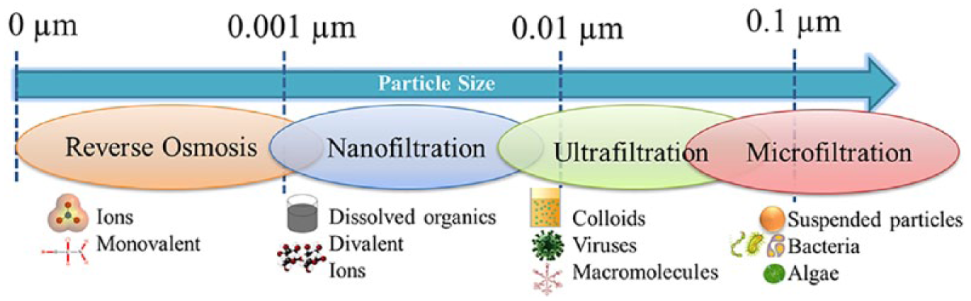
Particle size removal range by filtration.
PVDF electrospun nanofiber web in different thickness ranging from 144.4 mm to 1529.3 mm have been prepared and used for desalination of salty water by direct contact MD method. By increasing the electrospinning time, the thickness of nanofiber layer increased so did the liquid entry pressure of water (LEPw). On the other hand, the mean pore size of interfiber space decreased, whereas no significant changes were observed for the diameter of the electrospun fibers (1.0–1.3 mm), the void volume fraction (0.85–0.93), and the water contact angle (WCA; 137.4 – 141.1°). It was observed that permeate flux did not decline linearly with the thickness of the electrospun web. Moreover, the permeate flux reached a value of 15.2×10⁻³ kg/ m2 s (at water feed temperature of 80°C and a permeate temperature of 20°C), and the salt rejection factor was higher than 99.39%. During the 25 h DCMD operating time, no wetting was observed. 116
Ebrahimi et al. 117 prepared a novel triple-layer configuration with diameter gradient for PVDF nanofiber membranes for the DCMD application. Beads-free PVDF nanofiber layer with thinner diameter was used as an outer layer while thicker PVDF nanofiber layer was used in the middle layer. Results showed that single layer membranes showed a permeate flux 15.4 kg/m2h while triple layers have permeated flux in between 27.8 and 31.5 kg/m2h when salt rejection factors greater than 99.9% were achieved. Results indicate that different membrane configuration has a big role in the evaporation and permeate flux efficiency.
In another work, the surface of the nanofiborus PVDF membranes was modified with titanium dioxide (TiO2) and 1H, 1H, 2H, 2H-perfluorododecyl trichlorosilane (FTCS) doe desalination by DCMD. 118 The TiO2-FTCS modified PVDF nanofiber membranes possessed high roughness and hydrophobicity (157.1°) with a wetting resistance of 158 kPa and 57% surface porosity. During the short-term DCMD process, the permeate flux was achieved as 73.4 LMH (L/m2h) permeate flux with 99.99% salt rejection while 40.5 LMH permeate flux with 99.98% salt rejection was achieved for the long-term DCMD process using 3.5 wt% NaCl solution. Compared to commercial PVDF membrane (0.45 mm, HVHP4700, Millipore (Burlington, Massachusetts, United States), 46.2 LMH permeate flux), a significant improvement in efficiency was obtained.
In another approach, nanoparticle (NP; aluminum oxide (Al2O3)) enhancement PVDF nanofibrous membranes were fabricated using electrospinning system and AGMD was used to remove heavy metals (lead). 119 Results showed that commercial PVDF membrane (HVHP29325, 0.22 mm diameter, Millipore) exhibited the lowest flux of around 15 LMH while high fluxes between 16.5 LMH and 20 LMH have been shown by the neat and the composite PVDF membranes with Al2O3 NPs.
Polyacrylonitrile (PAN) electrospun membranes with nonwoven structure and quasi-parallel fibrous structure were used for lab-scale AGMD system. 120 The surface of PAN nanofibers was hydrophobized with surface fluorination treatment. It was found that in the surface fluorinated webs, the fiber orientation combing with the flow direction increased the mass transfer coefficient through the mem-brane and the MD performance in terms of permeate flux.
PVDF electrospun nanofibrous membranes doped with tris(phenanthroline)ruthenium(II) chloride (Ru(phen)3) were prepared and used for DCMD system. 121 The temperature sensitive Ru(phen)3 was used as a probe which allowed it to optically monitoring the membrane surface temperature during DCMD experiments. The doping with Ru(phen)3 confers to the PVDF membrane photochemical activity and its emission intensity linearly decreases by increasing the temperature. The molecular probes and infrared camera used as a tool for monitoring temperature on membrane surfaces online and in real time. During the process, the flux increased from 9 to 15.7 kg/m2h making the temperature of the feed stream rise from 40°C to 60°C, respectively; while the PVDF Durapore commercial membranes (Millipore) presented a flux of 10.67 kg/m2h at a feed temperature of 60°C.
Su et al. 122 prepared superhydrophobic nanofibrous membranes from silica NPs doped on PVDF fiber. Different dosages of silica NPs were added into PVDF solution for the electrospinning process. The hydrophobicity of the membranes altered by the dosage of silica NPs, and the WCA of the membranes optimized to be 157 + 1°. The characterization tests showed that the incorporation of silica NPs has altered the membrane surface morphology and endowed the composite membrane with the hierarchical structure on the surface and bulk layers as well as increasing the mechanical strength, salt rejection, and water permeation flux of the membranes. The nanofibrous membrane which contains 7.47 wt% silica NPs has a WCA of 152 + 1 and shows high DCMD performance with a water flux of 25.73 kg/m2h, salt rejection rate above 99.99%, and a permeate conductivity below 5.0 mS/cm during a 100 h test period.
TiO2 nanofiber that consists of ceramic membranes is designed and fabricated by vacuum filtration and fluorination modification. 123 The superhydrophobic titania nanofi-brous ceramic membrane is modified by fluorinated holds show an excellent desalination performance with the flux of 12 LMH with a salt rejection of 99.92% at 80 C and a good stability for long-term MD operation in pure and saline water which is compared to those of ceramic membranes with particle aggregation structure.124–127
Terpolymer (THV) membranes, which consist of tetrafluoroethylene, hexafluoropropylene, and vinylidene fluoride, are fabricated by the electrospinning method for MD application. 128 The advantage of using THV is their excellent hydrophobicity, mechanical properties, and chemical resistance. After optimization process, it was observed that membrane exhibited a good structure, wetting resistance, and surface hydrophobicity. The optimized membrane had a contact angle of 130.7°C with a mean pore size 0.79 mm, LEPw value of 118 kPa, tensile strength was 5.41 MPa, and the elongation at break was 247.9%, which were 2.47 and 5.61 times higher than those of the prepared PVDF film membrane, respectively. The permeate flux was measured as 4.42 kg/m2h with a salt rejection rate higher than 99.8%. The PVDF film membrane showed 1.93 times less flux than that of the THV membranes.
Jiřıček et al. 129 used PUR nanofiber layer with varying thickness produced by needle-free industrial electrospinning system for the DCMD process. Different concentra-tion of feed solution was prepared. Prepared nanofiber layer was laminated on a bicomponent polyolefin nonwoven surface to improve the mechanical property of the membrane. Results indicate that, even at the highest NaCl concentration in feed (100 g/kg), the best flux (around 6 kg/ m2h) and energy efficiency was achieved with thicker membranes (25 and 40 g/m2 basis weight of membrane).
In their other work, 82 PVDF nanofiber membranes were tested using the DCMD method. Results showed that PVDF nanofiber membranes had comparable permeate flux with commercially available polytetrafluoroethylene and polysulfone membranes. As a summary, the results indicate that nanofiber webs produced by industrial electrospinning device have a possible application in MD process.
Conclusion
In this review, the properties, the spinning parameters, and the application area of the electrospun nanofibers were discussed. Electrospinning method is a fascinating method to prepare membranes in micro or nanopore size. One can prepare porous structure using various polymeric electrospun nanofiber layers. Electrospun nanofiber layers have higher porosity with uniform pore size distribution compared to conventional membranes. The highly porous structure yields to increase the permeability of the membranes while high surface area allows membranes to be functionalized with ease. It was found that remarkable progress has been made in the fabrications of electrospun membranes for water treatment. MD is one of the most promising application fields for the electrospun nanofiber membranes. The porous structure, hydrophobicity, and the performance of the membrane are crucial for further developments in MD. This review reveals that possible application of nanofiber layers in MD.
Footnotes
Acknowledgements
The author would like to thank Mr. Frederick Fung for his help in language proof-reading.
Declaration of conflicting interests
The author(s) declared no potential conflicts of interest with respect to the research, authorship, and/or publication of this article.
Funding
The author(s) disclosed receipt of the following financial support for the research, authorship, and/or publication of this article: This work was supported by the Ministry of Education, Youth and Sports of the Czech Republic and the European Union—European Structural and Investment Funds in the frames of Operational Programme Research, Development and Education—project Hybrid Materials for Hierarchical Structures (HyHi, Reg. No. CZ.02.1.01/0.0/0.0/16_019/0000843).