
Abstract
Noncrimp three-dimensional orthogonal carbon weave is a specific type of three-dimensional woven fabric which is expected to have high performance as composite reinforcement. In this paper, two different orthogonal weaves in terms of carbon fiber tow type and binder yarns insertion density are produced, and a comprehensive study on the tensile strength of carbon composite reinforcements is conducted. The fiber volume fraction and mechanical performance are found to be affected by these two weave parameters. The fabric architecture changes due to different binder yarns’ insertion densities, influencing the stress wave propagation by preventing crack growth, thus leading to improve tensile strength of three-dimensional orthogonal reinforcement. Based on experimental weave parameters, a set of numerical compression tests are simulated by using a meso-scale finite element model. The results show that the model can predict the tensile strength of noncrimp three-dimensional orthogonal carbon composite reinforcements.
Keywords
Introduction
Three-dimensional (3D) woven fabrics are one of the fibrous reinforcements that are gaining attention of numerous researches in developing composite materials for various applications [1,2]. Three-dimensionally woven composites have been determined as a category of materials that offer large potential performance and manufacturing benefits for structural applications as they give supreme performance at significantly reduced manufacturing cost and time [3,4].
A less widely studied 3D fibrous reinforcement is noncrimp 3D orthogonal woven fabric which is called NC3DOW following [5]. This specialized subgroup of 3D woven fabrics is characterized with practically straight and well aligned in-plane fibers. These features distinguish this kind of fabric from other kinds of 3D woven, braided, and knitted fabrics [6]. Khokar [7,8] proposed the term “noobing”: non-interlacing, orientating orthogonally, and binding. This is an excellence for high strength NC3DOW fabricated from high performance fibers, e.g. carbon fibers which generally suffer from low abrasion resistance [9,10]. As a consequence of the uncrimped yarns, NC3DOW composites have shown significantly higher interlaminar properties and even higher in-plane stiffness or strength than composites reinforced with conventional 3D interlock weaves. The more straightforward structure of NC3DOW among 3D textile reinforcements results in a composite with high performance as well as reduced sensitivity to interlaminar shear [11,12].
Evidently, the mechanical functionality of NC3DOW reinforcement and its structural characteristics are considered as key factors in composites manufacturing processes as well as composite mechanical performance to develop desirable products. For instance, fiber volume fraction (FVF) is one of the most critical factors in the composites production processes as well as composite mechanical performance. As previously claimed by the researchers [3,13], the mechanical property and failure behavior of composites reinforced by NC3DOW are influenced by fabric yarn geometry and the FVF.
Most of the reported research on NC3DOW architectures so far has involved composites based on these preforms. Comprehensive experimental studies were carried out on the tensile, compressive, flexural, and ballistic impact behavior of composites reinforced with NC3DOW [14–18]. Clearly, a complete experimental investigation of the mechanical behavior of these composites and their dependence on all major construction parameters is infeasible due to the time and cost factors. In order to overcome these limitations, modeling approaches have been recently developed for understanding mechanical behavior of the composites [19]. In this regard, a number of analytical and numerical studies have been conducted by El Hage et al. [20], Shigang et al. [21], Topal et al. [22], Bedogni et al. [23], Ansar et al. [24], and Saleh et al. [25]. However, there are few works dealing with NC3DOW performance despite its 3D architecture uniqueness. The energy absorption and ballistic penetration damages of NC3DOW were investigated by Shi et al. [26], Jia et al. [27], and Carvelli et al. [28] through experimental tests and analytical and finite element models. Recently, some attempts have been made to investigate the tensile behavior of NC3DOW under quasi-static tension and high strain-rate states. Mishra et al. [29] have proposed a geometrical and micromechanical model for predicting tensile properties of NC3DOW. A unit cell of fabric was simulated by the proposed meso-finite element model in ANSYS. They declared that the model has successfully simulated the tensile properties of orthogonal fabric and can be used in other mechanical situations such as compression, shear, and bending. The impact tension behaviors of NC3DOW under high strain rates and quasi-static tension were investigated both experimentally and numerically by Hou et al. [30].
Despite the importance of weave parameters, especially binder yarn insertion, the effect of binder content on the tensile failure properties of NC3DOW has not been performed yet; this paper aims to deepen the knowledge of NC3DOW reinforcement in terms of tensile strength. Accordingly, an experimental study on the tensile failure properties of NC3DOW fabricated from two different carbon fiber tows with various binder contents is performed. Uniaxial tensile test is conducted to determine the influence of weave parameters on the tensile strength and elongation at break of NC3DOW preform, and failure mechanism is analyzed based on the results. To provide a detailed understanding of tensile strength before NC3DOW preforms is efficiently used in composites, a predictive model needs to be offered. In this study, a meso-scale finite element model is proposed to primarily analyze the mechanical behavior of NC3DOW and investigate the effect of weave parameters on the geometric characteristics and tensile strength. Investigating the tensile failure properties of NC3DOW reinforcements with various structural parameters will be helpful for analysis and design of composites regarding to their final application.
Experimental
Production of NC3DOW samples
Properties of T 300 carbon fiber tows.

CV: coefficient of variation.

Photograph of NC3DOW samples and schematic of warp/weft insertion density: (a) one layer per centimeter and (b) two layers per centimeter. 6K1D: 6K carbon fiber tow, one layer per centimeter warp/weft insertion density; 6K2D: 6K carbon fiber tow, two layers per centimeter warp/weft insertion density; 12K1D: 12K carbon fiber tow, one layer per centimeter warp/weft insertion density; 12K2D: 12K carbon fiber tow, two layers per centimeter warp/weft insertion density.
Specification of noncrimp 3D orthogonal carbon samples.

6K1D: 6K carbon fiber tow, one layer per centimeter warp/weft insertion density; 6K2D: 6K carbon fiber tow, two layers per centimeter warp/weft insertion density; 12K1D: 12K carbon fiber tow, one layer per centimeter warp/weft insertion density; 12K2D: 12K carbon fiber tow, two layers per centimeter warp/weft insertion density.
In order to calculate the FVF of noncrimp 3D orthogonal carbon weave, the volume of the sample is needed. It is difficult to measure the exact volume of sample because of spines at its edges. So FVF is determined by the weight of fibers in a 1 × 1 × 1 cm3 volume unit as follows:
The number of threads per centimeter in X, Y, and Z direction is calculated by the following equations
Schematic representation of a unit volume and the length of threads in X(Y) directions used for calculating FVF: (a) one layer per centimeter warp/weft density and (b) two layers per centimeter warp/weft density.


FVF of samples.
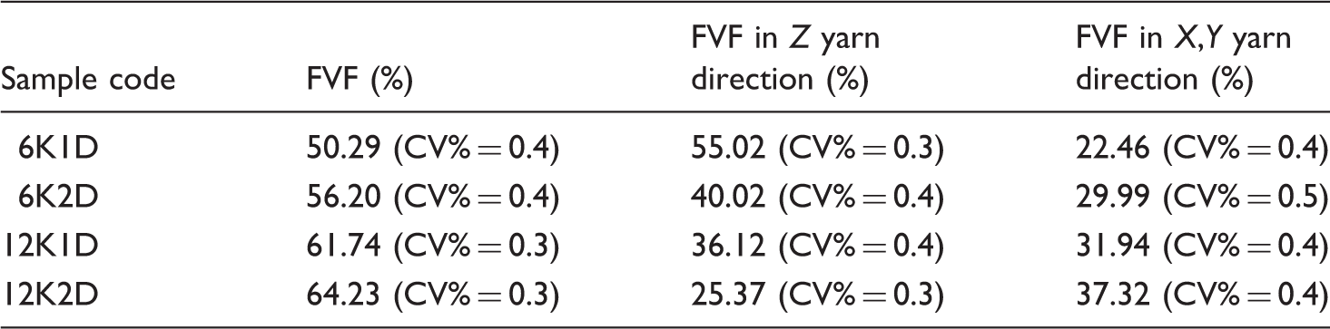
CV: coefficient of variation; FVF: fiber volume fraction; 6K1D: 6K carbon fiber tow, one layer per centimeter warp/weft insertion density; 6K2D: 6K carbon fiber tow, two layers per centimeter warp/weft insertion density; 12K1D: 12K carbon fiber tow, one layer per centimeter warp/weft insertion density; 12K2D: 12K carbon fiber tow, two layers per centimeter warp/weft insertion density.
Uniaxial tensile test
Uniaxial tension test is performed on specimens of NC3DOW using a SANTAM (STM-50) tensile tester with a 50 KN load cell at a velocity of 10 mm/min. Nominal specimen dimensions are set at 60 × 5 × 5 mm3 length, width, and thickness, respectively. In order to prevent the slippage between the samples and the grips, two ends of the fabric sample as shown in Figure 3 are solidified with epoxy resin to form composite. Three specimens are prepared to conduct tensile test under the same conditions at room standard condition as shown in Figure 4.
Photograph of a 3D specimen prepared for tensile test.
Meso-scale finite element modeling of the NC3DOW
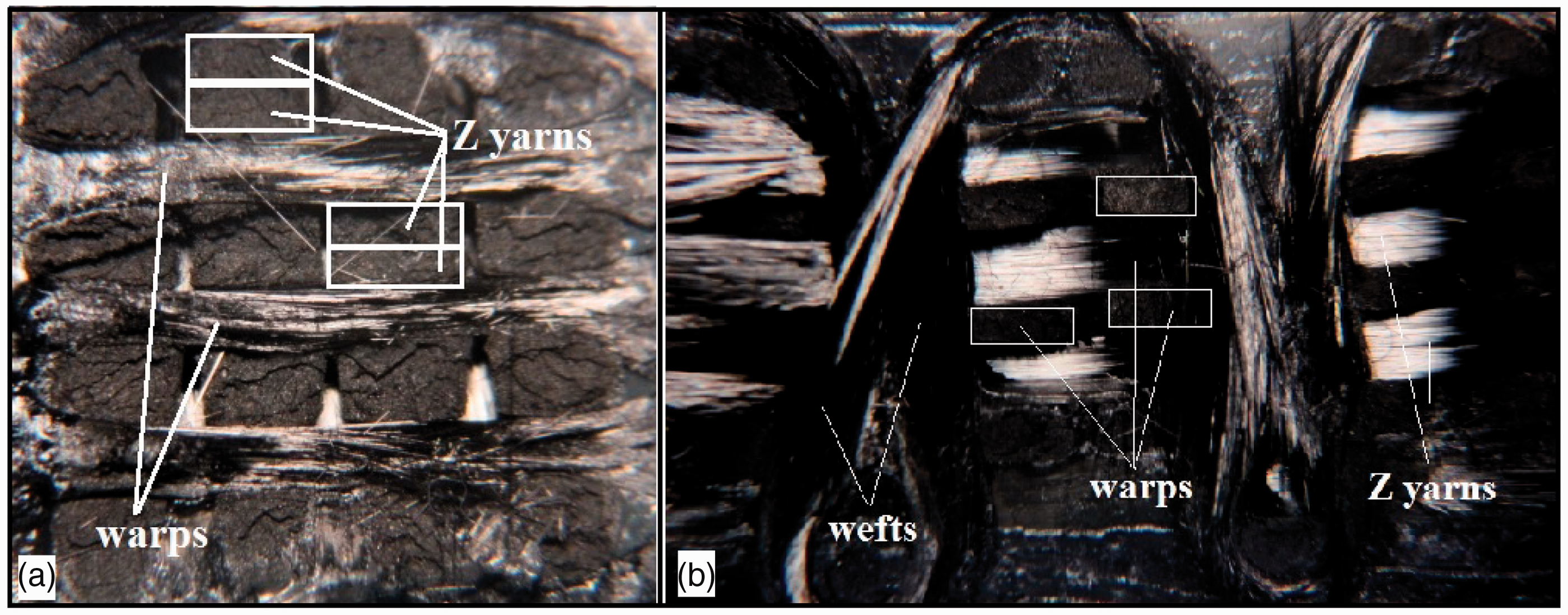
The commercially available software package ABAQUS/Explicit (Version 6.12) is used to conduct the finite element modeling of the tensile behavior of 3D carbon samples. The finite element analysis is carried out in the yarn level, and therefore, is called meso-scale [23]. In this type of fabric, there are three sets of yarn which are mutually perpendicular to each other. The first step of any finite element simulation is to discrete the actual geometry of the structure. Accurate design of structure geometry requires an understanding of the cross-sectional geometry of the yarns as well as their path. In order to observe the internal structure of NC3DOW directly, the samples are consolidated with hot melted glue, sectioned, polished, and observed under an optical microscope as shown in Figure 5. As the figure shows, the cross-sectional shapes of carbon yarns are very close to rectangular. Therefore, in order to simplify the finite element model and to be consistent with the sample’s structure, the carbon yarns in NC3DOW architecture are modeled as a homogeneous continuum with a rectangular cross-section as some previous studies [20,23]. The dimensions of each type of carbon yarn cross-section are obtained by averaging data from the realistic cross-sectional shape according to the proposed method described by Tan et al. [19]. Considering the data, a meso-geometrical model of fabric is established by computer-aided engineering (CAE) software CATIA (ver. V5-R17) as depicted in Figure 6.
NC3DOW carbon sample under uniaxial tensile test. Internal geometry of NC3DOW sample: (a) section parallel to warp direction and (b) section parallel to Z yarn direction. Geometrical model and NC3DOW carbon sample: (a) one layer per centimeter warp/weft density and (b) two layers per centimeter warp/weft density.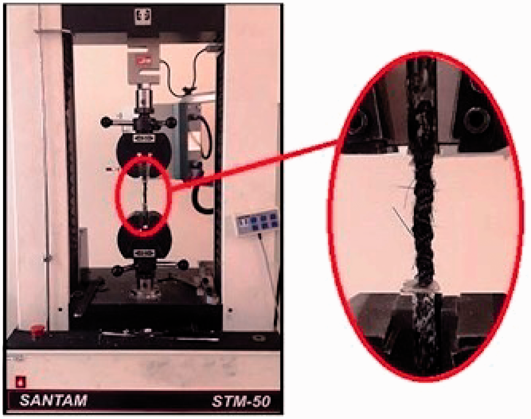

Mechanical properties of carbon fiber tows.

CV: coefficient of variation.

Mesh schemes and loading condition of finite element model of NC3DOW carbon sample: (a) one layer per centimeter and (b) two layers per centimeter.
Results and discussion
Experimental results and statistical analysis
Figure 8 shows the force–extension curves of one noncrimp 3D orthogonal carbon sample until failure, and Table 5 lists the averaged tensile strength and elongation at break from all specimens. It should be noted that because of discontinuity of the porous fabric structure, the results are reported in load–extension form instead of stress–strain. So the maximum failure force and elongation at break are reported.
Force–extension curves for 6K1D specimens under tensile loading. 6K1D: 6K carbon fiber tow, one layer per centimeter warp/weft insertion density. Tensile properties of NC3DOW samples. CV: coefficient of variation; 6K1D: 6K carbon fiber tow, one layer per centimeter warp/weft insertion density; 6K2D: 6K carbon fiber tow, two layers per centimeter warp/weft insertion density; 12K1D: 12K carbon fiber tow, one layer per centimeter warp/weft insertion density; 12K2D: 12K carbon fiber tow, two layers per centimeter warp/weft insertion density.

Force–extension response of 3D carbon samples under tensile loading showed good experimental agreement in results between the specimens. The small initial nonlinear portion of this curve is due to straitening of uneven and crimped yarns in 3D structure. Although the warp and weft carbon tows are designed to be noncrimp in structure, the real sample shows a certain degree of waviness [37]. Following this stage, the fabric structure becomes tightened and the yarns better oriented. Therefore, linear stage which is similar to a solid composite occurs [38]. The fracture morphology of the NC3DOW carbon specimen under uniaxial tensile test is shown in Figure 9.
Photograph of tensile fracture of NC3DOW carbon samples: (a) 6K1D, (b) 6K2D, (c) 12K1D, and (d) 12K2D.
According to ANOVA analysis carried out at 95% significant level [39], weave parameters including carbon fiber tow type and warp/weft insertion density have significant effect on FVF and tensile properties of NC3DOW samples.
Tensile test results of NC3DOW indicate the uniqueness of this structure. The stress concentration at the interlacing points, which results in fast microcrack growth and premature failure of fabric specimen [40] is much less than other kinds of 3D woven fabrics. When the tensile load is applied along the Z yarns direction, a small portion of the load is transferred to the warp and weft yarns. The straight Z yarns are the first to bear the tensile loading and the stress wave is transmitted to the warp and weft yarns at the contact areas. Although carbon yarns tend to break because of their defects such as microcracks and narrow necks, the warp and weft yarns improve the tensile performance of Z yarns bundle by increasing internal friction during tensile loading which causes energy dissipation in the form of heat as well as preventing crack growth [30,41,42]. Furthermore, high tensile strength of NC3DOW is due to noncrimped 3D orthogonal architecture of this fabric rather than to mechanical properties of its yarn bundles.
Duncan analysis for comparison means of tensile results of samples [39] confirms that increasing the warp/weft insertion density will significantly increase both failure force and elongation at break. Obviously, the FVFs of structure occupied by the fiber alone in the warp and weft directions as shown in Table 3 are higher in samples with two layers per centimeter warp/weft insertion density. Precise investigation reveals that fiber content increase leads to fiber–fiber contact in 3D structure [43]. Thus, the dispersion and transmission of the stress wave in the dense structure are much more intense than those with only one layer per centimeter density due to the better yarn contact and interlacing conditions. As a result, the internal friction of 3D orthogonal structure could be significantly increased if the warp and weft layers increase. This will improve the structure resistance and its tensile properties regarding to failure force and elongation at break by excluding crack development and decelerating their growth rate. It can be concluded that the two yarn sets which are not oriented in loading direction play an important role in tensile properties of noncrimp 3D orthogonal carbon composite reinforcement.
Results of the finite element simulation
In order to validate the simulated finite element model, the predicted results are being compared with the experimental data achieved from the uniaxial tensile test. The predicted force–extension curves of noncrimp 3D orthogonal carbon samples under uniaxial tensile loading in comparison with the averaged experimental results are given in Figure 10. The maximum forces obtained in the finite element model show an appropriate agreement with the experimental values and the percentage of error is in the range of 3–10%. As the comparison shows, the maximum load of 3D orthogonal samples on the experimental results is more than the numerical prediction. As previously mentioned, this can be attributed to unique architecture of NC3DOW which has three noncrimped orthogonal yarn sets. The warp and weft yarns have a significant impact on improving tensile strength of the structure. Higher experimental failure force can be a desired result since there is a confidence level in the predicted value. It is well known that carbon yarns generally suffer from low bending and abrasion resistance and are inclined to be eroded with the weaving loom elements [10]. Obviously, damaged carbon fibers would result in a reduction in mechanical properties of the reinforcement and final composite [44].
Comparison of the experimental and the finite element model results in force–extension curves of NC3DOW under uniaxial tensile loading: (a) 6K1D, (b) 6K2D, (c) 12K1D, and (d) 12K2D. 6K1D: 6K carbon fiber tow, one layer per centimeter warp/weft insertion density; 6K2D: 6K carbon fiber tow, two layers per centimeter warp/weft insertion density; 12K1D: 12K carbon fiber tow, one layer per centimeter warp/weft insertion density; 12K2D: 12K carbon fiber tow, two layers per centimeter warp/weft insertion density.
As seen in Figure 10, the predicted elongation at break values is lower than the experimental ones. It is noticed that experimental values of the elongation at break for 3D samples are about 3–5% while the numerical predicted values are about 1.6–2% which are the elongation values defined for yarn breakage according to Table 1. This is because the actual structure architecture differs from the idealized design. The Z yarns are designed as fully straight parts with no slack in the finite element model. While the yarns in a real fabric are relaxed after weaving process and the tensile loading applied to the 3D structure is utilized for straitening of loose and uneven Z yarns at the first stage. That is why there is no initial nonlinear portion in the force–extension curve obtained from the finite element model. By removing the low slope part of experimental curves caused by uneven and crimped yarns in 3D structure, the acceptable agreement between experimental and finite element results can be seen in Figure 11 clearly. As previously explained, the warp and weft yarns assistance also improve the fabric elongation at failure, while this aspect is very inconspicuous in the finite element model due to simpler contact between threads. As can be seen from the finite element results shown in Figure 11, the maximum force and the elongation at break both increased with increases of the warp/weft yarn insertion density but it is not significant. The overall damage evolution of noncrimp 3D orthogonal carbon composite reinforcements during numerical simulation is shown in Figure 12.
Comparison of numerical predicted and experimental results of NC3DOW under uniaxial tensile loading: (a) maximum force and (b) elongation at break. FE: finite element; 6K1D: 6K carbon fiber tow, one layer per centimeter warp/weft insertion density; 6K2D: 6K carbon fiber tow, two layers per centimeter warp/weft insertion density; 12K1D: 12K carbon fiber tow, one layer per centimeter warp/weft insertion density; 12K2D: 12K carbon fiber tow, two layers per centimeter warp/weft insertion density. Ultimate damage morphology of NC3DOW predicted by finite element model: (a) 6K1D, (b) 6K2D, (c) 12K1D, and (d) 12K2D. 6K1D: 6K carbon fiber tow, one layer per centimeter warp/weft insertion density; 6K2D: 6K carbon fiber tow, two layers per centimeter warp/weft insertion density; 12K1D: 12K carbon fiber tow, one layer per centimeter warp/weft insertion density; 12K2D: 12K carbon fiber tow, two layers per centimeter warp/weft insertion density.

Conclusion
This paper is an effort to experimentally and numerically investigate the tensile strength of noncrimp 3D orthogonal carbon composite reinforcement under uniaxial tensile loading. It was found that noncrimp 3D carbon samples have high FVF and tensile properties due to their highly straight structures. The observed large tensile strength in this structure was attributed to the uniqueness of the structure regarding to crimpless architecture, which eliminates stress concentration, and also to the key role of warp and weft yarns by increasing internal friction and preventing crack growth. There was a significant difference in FVF, tensile strength, and elongation at break of NC3DOW samples among two carbon fiber tow varieties and two warps and weft yarns insertion densities. The maximum measured ultimate tensile strength and elongation at break values were 26,316.32 N and 5.01%, respectively, for 12K2D samples. Employing a meso-scale finite element model, the tensile behavior of NC3DOW was simulated in this study. Based on the results, the simplified geometrical model proposed herein is capable of predicting the tensile behavior of noncrimp 3D orthogonal structures. Therefore, it can be useful to predict the mechanical properties of both the noncrimp 3D orthogonal carbon fabrics and composites.
Footnotes
Declaration of conflicting interests
The author(s) declared no potential conflicts of interest with respect to the research, authorship, and/or publication of this article.
Funding
The author(s) received no financial support for the research, authorship, and/or publication of this article.