
Abstract
This paper reports the mechanical response of semi-hexagonal part with three different multi-layer reinforcements. Unidirectional, plain woven and orthogonal fabric under quasi-static axial compression were considered. Meso-scale finite element numerical models with failure criterion were also established to simulate the onset and development of internal damage during the compression process. There were two different crush-failure modes occurring in the crush tests of the three different composite samples: a splaying mode for samples with unidirectional fabric, a buckling mode for samples with 3D orthogonal woven fabric and a mixture mode of both buckling and splaying for samples with the plain woven fabric. The samples reinforced by unidirectional fiber have the highest specific energy absorption and lowest peak loading, whereas the samples by 3D orthogonal fabric present the lowest specific energy absorption and highest peak loading. It was also demonstrated by a numerical model that the existence of Z-binder suppresses the delamination by restraining the expanding of warp and weft yarns. The comparison of numerical results and experimental data indicates that the structure of reinforcement has a significant role in the mechanical performance of textile composite.
Introduction
Advantages of textile composites include better vibration damping properties, higher strength-to-weight ratios and impact resistance [1,2]. They have wide applications in the aerospace, automobile and ocean engineering field. The ability of short manufacturing cycle and near net shape production enables textile composite to be a cost effective replacement for laminated composite.
The structure of the reinforced fabrics plays an important role in the mechanical response of textile composite under various loading conditions [3,4]. Therefore, the mechanical characterization of textile composite has been a growing scientific field in recent years because of the diversity of reinforced fabrics. Typically, fabric structures in textile composite include unidirectional, two-dimensional plain, and twill woven fabric [5–7]. Those fabrics are stacked up to form dry reinforcement for obtaining specific thickness and high fiber volume fraction.
To overcome delamination and poor through-thickness properties in stack-up system, fabrics with three-dimensional (3D) architecture have been employed as reinforcement and their mechanical behaviors have been investigated. Due to high strength-to-weight ratio in impact protection applications, the impact performance of 3D woven composites has been studied by many researchers [4]. The damage of 3D woven composites that are subjected to drop weight impact appears to be highly localized and spreads in the thickness direction [8]. The reason for this is that the Z-yarn maintained the structural integrity and promoted deep indentation of the tup, and thus intensive energy dissipation by yarn splitting, fiber breakage, and formation of a plug by out-of-plane shear [9]. In addition, the influence of Z-yarn on 3D woven composite during high-speed impact has been exhibited by several numerical models [10,11]. On the other hand, the influence of Z-yarn on on-axis and off-axis tension mechanical properties was also studied [12]. They found that the Z-yarns in 3D orthogonal woven composite suppress the localized damage and allow larger fiber rotation. The multi-scale damage model of 3D woven composites under uni-axial tension was also presented to deeply understand the damage initiation and progression [13]. A comprehensive comparison of fatigue performance of 3D woven composites with different fabric architectures have been performed [14,15]. Despite these potential benefits, there is currently a lack of knowledge about how damage develops in 3D woven composite under compressive loads. The onset and growth of compressive damage which relate to the yarn structures are discussed [16,17]. They found that the Z-yarn structure has a profoundly influence on the growth of damage. Compression strength and failure mechanisms were shown to be very dependent on the yarn crimp [18]. Inspection using X-ray computer tomography implied that failure initiated in a highly crimped area in the Z-yarn plane leads to further failures in warp yarns. The compression with different strain rate was applied to the composite samples reinforced by 3D orthogonal woven fabric in warp, weft and through-thickness direction [19]. The failure in through-thickness compression was in an inclined shear band style, while the failure in warp and weft direction is in a 'broom' end style without delamination. Therefore, the z-yarn retarding the delamination contributed significantly to the in-plane compression response. From the foregoing, diversity architecture provides large opportunity for designing the performance-oriented textile composite. The appropriate selection of fabric architecture is indeed very important from the perspective of composite mechanical properties.
In review of the above references, these studies mentioned are mainly focused on specimen with regular profile. Recently, the mechanical response of engineering part at structural level attracted more attention due to the increasing application. The failure mode and specific energy absorption of double hat shape CFRP tubes reinforced by woven fabric were investigated by experimental method [20]. The axial quasi-static crush response of semi-hexagonal composite structures with different material system was studied using experimental method [21]. The composite part reinforced by E-glass plies possessed higher energy absorption ability due to the delamination and corresponding stable collapse mode, while the basalt/polyester samples exhibited unstable collapse and corresponding low SEA due to the buckling effect. In addition, properly designed triggers were introduced to influence the failure mode and associated energy absorption capacity under axial loading [22,23]. However, there have been fairly limited studies concerning evaluation of mechanical performance of engineering part with different fabric structure. The unidirectional, plain woven and 3D woven, which are typical reinforcements used in structural parts, have obvious difference in pattern. For better understanding of crashworthiness of CFRP part with the structure of different fabric, the three types of fabric were used to fabricate semi-hexagonal composite part by vacuum-assisted resin transfer molding (VARTM) technology. Both numerical and experimental methods were used to investigate their mechanical behaviours under axial quasi-static crushing condition in this study.
Experiments
Specimen preparation
The semi-hexagonal component is commonly used for lightweight structure. As shown in Figure 1, it can be found in B pillar of new energy vehicle. The geometry of component is illustrated in Figure 1, and the thickness, width, overlap length of the sample section are taken as 4, 44 and 7 mm, respectively. The length of all the samples is 60 mm, and the structure of textile reinforcement is only variable parameter.
The profile of semi-hexagonal.
In order to study the effect of fabric structure on the mechanical behaviour of composite, three types of textile with structure of unidirectional, plain woven and orthogonal woven fabric were fabricated and cured into semi-hexagonal parts.
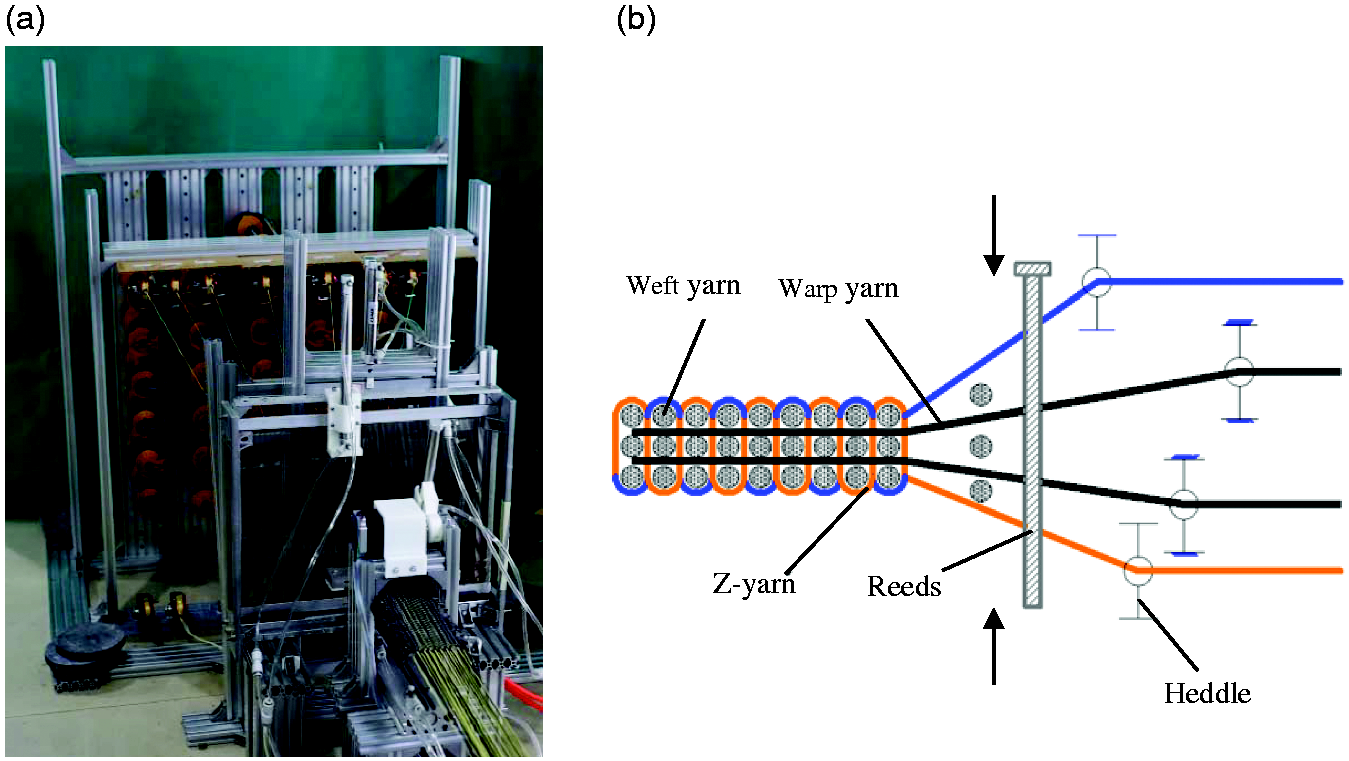
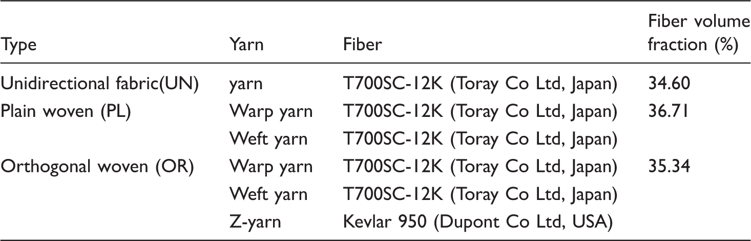
In Figure 2(a), the unidirectional fabric consists of parallel T700SC-12K carbon fibers that are fixed by fine nylon threads. Its reinforcement is stacked in [0/90] alternation for five layers. The plain woven fabric made up of three layers of plain fabric that was manufactured by T700SC-12K carbon fiber is presented in Figure 2(b). As shown in Figure 2(c), the 3D orthogonal woven consists of fibers in three directions, the T700SC-24K carbon fiber for warp, the T700SC-12 K carbon fiber for weft yarn and the 950 Kevlar for Z-yarns. The 3D orthogonal woven fabrics were manufactured by a home-made loom. The loom and its working principle are shown in Figure 3. Two layers of warp yarns are arranged in parallel and straight through reeds, while three layers weft yarns are driven back and forth by a rapier along vertical direction. The Z-yarn driven by heddles move up and down along the thickness direction to bind the warp and weft together and form a stable structure. The fabric types and the number of plies for the three fabric structures are listed in Table 1.
Structure of fabric reinforcement: (a) unidirectional reinforcement fabric; (b) plain woven fabric; (c) orthogonal woven fabric. The 3D orthogonal loom. (a) Prototype photograph and (b) schematic of weaving process. Specifications of the woven fabric.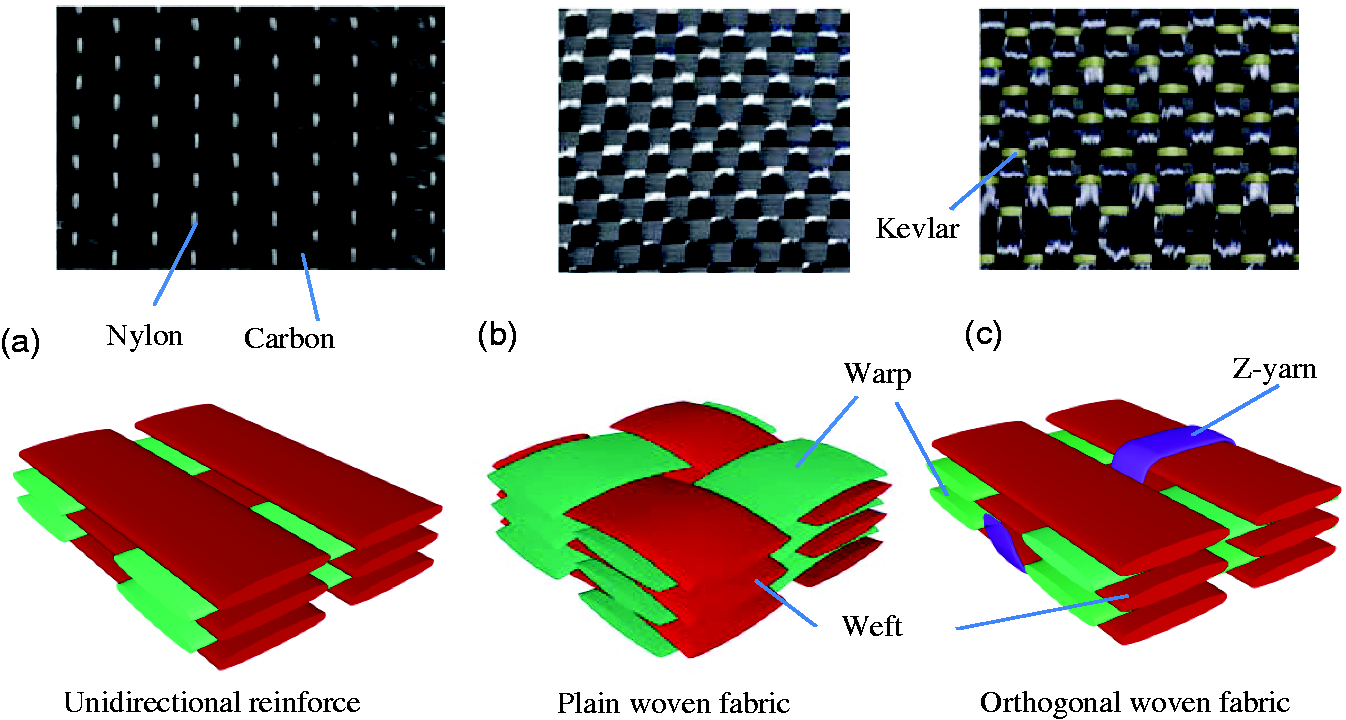
Peak load predicted by the models with different element number.

Testing procedure
Quasi-static compression tests were carried out on all the samples under the same condition, the speed of 2 mm/min over the distance of 20 mm, using a universal material test machine equipped with a 100 kN load cell. Three samples were tested for each configuration in order to ensure the repeatability of the experiment. The following mechanical characteristics were calculated from force–displacement curves.
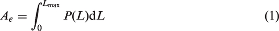
The peak load Pmax (kN) is the maximum force at the peak of curve. The absorbed energy Ae (J) is the area under the force–displacement curve and calculated in equation (1), where P is the force value and L is the collapse displacement.
The mean load of crush process is Pmean (kN), which is defined as the absorbed energy per sample length Lmax (mm)

The specific energy absorption (SEA) (J/g) is the energy absorption per unit of crushed sample mass M (g), calculated as
Numerical method
To further characterize the mechanical behaviour of semi-hexagonal composite structure, a full scale finite element technique was employed to simulate the crushing process on commercial platform ABAQUS. Taking the orthogonal woven fabric composite as an example, the modelling method is introduced in the following sections.
Geometrical model
The geometric model of orthogonal woven fabric (Figure 4(a)) composite is composed of two parts, namely fabric reinforcement and resin. The fabric reinforcement was assembled by three sets of yarn involving warp, weft and Z-yarn as shown in Figure 4(b). The warp yarn path is straight and parallel to the load-direction, while the weft yarn in transverse direction of semi-hexagonal structure is represented by a segment polyline. They are locked by Z-yarn that undulates along the warp direction. To reduce the computational cost and improve the calculation convergence, weft, warp, and Z-yarn are assumed to be perpendicular to each other and have an unchanged rectangular cross-section. The cross-section size of warp, weft and Z yarn are 2 mm long and 0.4 mm wide, 2 mm long and 0.4 mm wide, 0.5 mm long and 0.2 mm wide, respectively. A cross-section was swept along a centreline to form yarn geometry. Those yarns were assembled into a fabric reinforcement in a 3D CAD platform Solidworks. Then the geometry model in STL format was exported into a finite element pre-processor Hypermesh. In order to improve the mesh quality in the space between yarns and avoid interference among yarns, the fiber volume fraction was reduced in the geometric model. The resin could be obtained by extracting the geometric model of fabric reinforcement from the semi-hexagonal profile.
Geometry of orthogonal woven fabric composite and material orientation: (a) geometry model of orthogonal woven fabric composite; (b) geometry model of fabric reinforcement; and (c) material orientation definition of one Z-yarn treated as transversely isotropic composite.
The two parts are discretized with tetrahedral mesh for good fitting characteristics. The fabric reinforcement and resin were meshed together to obtain common interfacial nodes, which ensure that they have the same strain at the interface. In the numerical model, the total number of elements was around 650,000, and all the simulations were run on a workstation with an intel (R) Xeon (R) CPU E3-1230 v3, 3.30 GHz and 16 GB RAM. In order to assess the mesh sensitivity of the models, a convergence study was conducted, and the results are summarised in Table 2.
Constitutive law of textile composite
Mechanical properties of the resin.


Mechanical properties of dry fibre.

Ductile and shear damage failure criteria in ABAQUS are employed to calculate the damage initiation and progressively development of impregnated yarn and resin. The two kinds of failure criteria are simplified by Hooputra et al. [24] for making it easy to obtain relevant parameters through simple experiments. The parameters of the damage criterion in this work were set according to Zhou et al. [25].
For the ductile damage criterion, the equivalent plastic strain is a function of the stress tri-axially


The damage initiation criterion is met when the following condition is satisfied

After damage initiation, the material stiffness was degraded gradually according to the specified damage evolution law based on the energy dissipated during the damage process. The damage evolution law describes the rate of degradation of the material stiffness once the corresponding initiation criterion has been reached. It assumes that the degradation of the stiffness associated with each active failure mechanism can be modelled using a scalar damage variable, di(i∈
At any given time during the analysis, the stress tensor is given by the scalar damage equation

Result and discussion
Experimental results
Results of quasi-static compression test.

SEA: specific energy absorption.
Figure 5 plots typical load–displacement curves for three types of composites under quasi-static compression. All curves could be divided into three regions, namely the linear increasing, rapid falling and stable platform. In the linear increasing region, the loading climbs straightly to the peak loading, in which the ratio of loading increment to displacement increment is defined as compression stiffness. There is a slight difference of compression stiffness between the three types of material due to the variation of reinforcement structure. The highest stiffness exists in the unidirectional fabric sample, while the orthogonal woven fabric has the lowest stiffness.
Force–displacement curves of composite part under compression.
After reaching the peak loading, all curves drop down suddenly. With respect to unidirectional fabric composite, the curve falls to a specific point and then enter stable platform, which means the material owns the ability to absorb energy continuously during damage propagation. By contrast, the longer transition phase is observed in the curve of orthogonal woven fabric composite and this phase indicates that the materials progressively lose the capacity of supporting load. As for the plain woven fabric composite, the load–displacement curve presents a moderate trend to stable platform.
Crushing failure mode
In order to study the influence of fabric on failure modes of composite materials, the influence of semi-hexagonal structure on failure modes should be eliminated. Thus, a numerical model of semi-hexagonal structure with homogeneity property was built in ABAQUS, and the stress distributions and deformation process are exhibited in Figure 6. At the beginning of compression, the stress concentration was observed in the middle area of concave surface. With the increase of the loading displacement, a transverse crack occurred at the concave surface. Therefore, the failure mode of the semi-hexagonal structure is inclined to buckling, as shown in Figure 6(b).
The numerical mode crushing process of isotropy semi-hexagonal structure: (a) the stress concentration in the middle area of concave surface; (b) a transverse crack at the concave surface.
The mechanical performance of composites heavily depends on its failure mode. The onset and propagation of damage in three types of composite are examined in the following. A typical load–displacement curve of unidirectional fabric composite and damage photos at three displacement points is depicted in Figure 7. At point A where the peak loading is just exceeded, a crack occurred at bottom of the sample, followed by the debonding between fiber and resin. The sample was delaminated, causing the fiber to spread over the fixed tool. As the compression increased, the sample was divided into two parts and gradually formed a stable failure mode, which is defined as splaying mode.
The failure process of unidirectional fabric composite under compression. The displacements are: (a) 1.0 mm; (b) 5.4 mm; (c) 7.8 mm respectively.
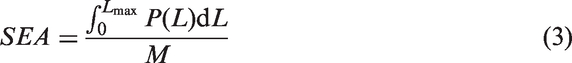
For the orthogonal woven fabric composite, the initial crack along transverse direction was found in the middle of sample in Figure 8. When the compression displacement is 1.2 mm, a local buckling generated, which lead to a buckling mode. The sample fractured in the middle part, which caused instability that made the reinforcement fiber partially lose its ability to absorb the energy and lowered the SEA value of the orthogonal woven fabric composite.
The failure process of orthogonal woven fabric composite under compression. The displacements are: (a) 1.2 mm; (b) 5.0 mm; (c) 11.2 mm respectively.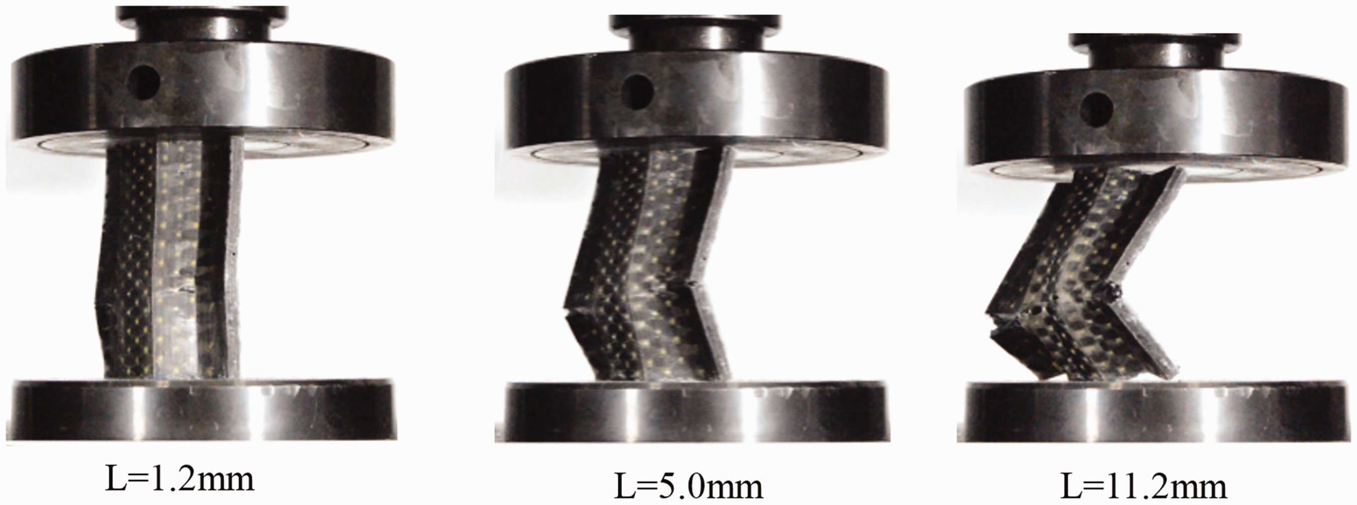
The delamination and local buckling were simultaneously found in the samples reinforced by plain woven fabric, which is defined as mixture mode (as shown in Figure 9). The delamination of sample with plain woven fabric is assumed to be attributed to the lack of interlayer constraint, which is similar to the unidirectional fabric composite. In the late stage of destruction, the filaments that had lost the support from resin were still interwoven and prohibited from moving aside. This phenomenon impeded the further delamination and created the possibility for the generation of buckling.
The failure process of plain woven fabric composite under compression. The displacements are: (a) 2.4 mm; (b) 9.4 mm; (c) 14.5 mm respectively.
In the previous discussion, there are two types of damage behaviour in terms of delamination and transverse cracking found in the axial compression process. The behaviours are induced by the structure of reinforcement and play a decisive role in the axial crushing response. For further understanding the effect of fabric structure on the damage behaviour, it is necessary to compare and analyze the unidirectional woven fabric composites without constraint and orthogonal woven fabric composites with perfect interlayer constraint.
Effect of fabric structure
To further investigate the effect of fabric reinforcement on the damage behaviours found in axial compression of semi-hexagonal component, two full-scale FEMs for unidirectional fabric composite and orthogonal woven fabric composite were developed. Figure 10 illustrates a good agreement between numerical and experimental results. For the unidirectional fabric composite, additional support is provided in axial compression experiments by nylon monofilament which was used for fixing carbon fiber in the sample as shown in Figure 10(a). The discrepancy between numerical and experimental results might come from the use of an oversimplified constitutive law, the lack of simulated confinement tension from the reinforcement and a subsequent increase in frictional forces between yarns.
Load–displacement curves comparison between experiment and simulation: (a) unidirectional fabric composite and (b) orthogonal woven fabric composite.
For the sake of discussing the formation mechanisms of two failure mode, the stress distributions and deformation process of fabric reinforcement extracted from geometric model are exhibited in Figures 11 and 12 for two types of fabric composites, respectively. As indicated in Figure 11(a) and Figure 12(a), the stress in warp yarn of orthogonal woven fabric reinforcement is obviously higher than that of unidirectional fabric reinforcement at the peak loading point. This contributes to the difference of peak loading between two types of fabric reinforcement. It is also observed that there is a certain amount stress in Z-yarn that restricts the separation of weft yarns. It leads to the increase of weft yarn tension due to mutual restraints between weft yarns and Z-yarns in orthogonal woven fabric, which supplies more sustentation on warp yarn than the counterpart in unidirectional structure does. Therefore, the orthogonal woven structure grants warp yarn better bearing capacity. Besides, due to the binding of Z-yarn, the orthogonal woven fabric obtains greater integrity, which means that the sample presents a buckling failure mode under the compression.
The comparison between simulation and experiment for composite part with unidirectional fabric (a) stress distribution in reinforcement; (b) stress distribution of composite part; and (c) experimental photos. The comparison between simulation and experiment for composite part with orthogonal woven fabric (a) stress distribution in reinforcement; (b) stress distribution of composite part; and (c) experimental photos.

Figure 11(b) shows that at the point A (the initial damage state of unidirectional fabric composite), the cracks occurred at the ends of unidirectional fabric composite. These were caused by stress concentration. As the compression displacement further increased, the cracks gradually propagated along the loading direction. Due to the lack of the constraints, the warp yarn in loading direction was pushed to both sides, as shown in point B (Figure 11(b)). It in turn formed a high stress area in the middle of separated layers, which increased the crack growth. Finally, the end of material formed continuous fronds, which was bent against the structure surface as multi-layered composite delaminated into separated layers (Figure 11(b) point C). With the splaying mode, the unidirectional fabric composite shows great energy absorption characteristics, as proved in Table 4.
However, due to the existence of Z-yarns, the orthogonal woven fabric composites exhibit buckling failure modes different from unidirectional fabric composites. Figure 12(b) shows that at the point A, the load was mainly sustained by the fabric reinforcement. It can be observed from the stress distribution of resin that the stress accelerated within the middle area compared to the two ends. For the strong inter-layer constrain provided by Z-yarn in the orthogonal woven reinforcement, the cracks were prevented from spreading along the load direction, and hence the separation between layers was inhibited. Since the delamination failure could not be initiated, the structure was kept in one piece and the buckling phenomenon would emerge with the increase of displacement.
As shown in Figure 12(b) point C, a transverse crack was nucleated in the middle area of the concave surface. The reason for this phenomenon is that the semi-hexagonal structure under axial compression is prone to bend kinking. The stress near the crack dropped rapidly and the bearing area reduced towards the opposite surface. At point C with the propagation of crack throughout the thickness direction, the sample finally lost the bearing capacity.
Conclusion
This work comprised a complete study of quasi-static behaviour of semi-hexagonal part reinforced by three different types of fabric, namely unidirectional fabric, 3D woven fabric and plain woven fabric under axial compression loading. The axial compression tests were carried out on samples to understand their mechanical response and failure modes. Numerical models were also developed and its results were compared with the experimental data. The main conclusions drawn from this work are the following:
It was found that the highest peak loading was in the 3D orthogonal fabric and the lowest loading was in the unidirectional fabric. An increase of peak loading could be caused by the increasing mutual restraints among yarns from stack-up unidirectional to 3D orthogonal woven fabric, via stack-up plain woven fabric. There were two failure modes occurring in the crush tests of the three different composite samples: A splaying mode for samples with unidirectional fabric, a buckling mode for samples with orthogonal woven fabric and a mixture of both buckling mode and splaying mode for samples with the plain woven fabric. A numerical model was used to demonstrate the role of z-yarn. The zig-zag z-yarn in loading direction confines the separation of weft yarn, which in turn provides more support for the warp yarn, which leads to a better load-bearing capacity and buckling failure mode. On the contrary, the lack of restriction between yarns in different directions leads to a trend to delamination phenomenon.
Footnotes
Declaration of conflicting interests
The author(s) declared no potential conflicts of interest with respect to the research, authorship, and/or publication of this article.
Funding
The author(s) disclosed receipt of the following financial support for the research, authorship, and/or publication of this article: This work was supported by the National Natural Science Foundation of China (Grant No. 51775514 and 51705466) and Zhejiang Provincial Natural Science Foundation of China under Grant No.LR18E050001.