
Abstract
Electrically nonconductive composites are required in various engineering applications ranging from radome, antenna and many more. This research aims at investigating the mechanical properties of electrically non-conductive hybrid composites (thin carbon non-crimp fabric, Kevlar and E-glass fabrics) in combination with thermosetting epoxy resin. The composites comprise of multi-axial textile reinforcement carbon fabrics in the middle section with symmetrical quasi-isotropic layup, sandwiched with Kevlar fibre for improved impact performance and E-glass fibre at the outermost parts for electrical insulation. The fabrics are injected with room-temperature-cure epoxy using economical and energy saving resin transfer moulding manufacturing process. Electrical continuity tests and mechanical properties including vibration damping response, flexure and impact were studied to investigate the performances of the manufactured hybrid composites. Three hybrid laminate configurations were manufactured, and experimental results showed that hybrid composite with more number of Kevlar layers performed better for vibration and flexure testing. For impact performance, results showed that the absorbed impact energy improved with the inclusion of more glass layers, whereas configuration with more Kevlar layers experienced greater peak load to failure. The details of the composites fabrication, manufacturing and experiments conducted and the related findings with underlying reasons for the improvement offered by particular group of laminate configuration are discussed in the article.
Introduction
Fibre reinforced composites are widely used in weight sensitive industrial applications due to excellent stiffness and strength combined with low density [1–3]. However, fibre reinforced composites usually have low toughness accompanied with the high strength properties. Many researchers have carried out the study on toughening strategies of composites, making the composite to be more damage resistant and less brittle. The revival of research interest in ‘hybridization’ led to the re-emergence of hybrid composites. Variants of hybrid composites were introduced to satisfy the need of new lightweight materials with improved toughness, catering specific industry requirements. The most economical production method is the interply method. This type of hybrid composite is produced by layup of dry fabrics or prepreg. Several studies had been done to investigate the effect of fibre dispersion on mechanical properties of hybrid composites [4–6]. Fibre dispersion was defined as reciprocal of the smallest repeat length [7,8]. For many years, pre-impregnated fibres or prepreg were favoured in industrial applications due to their high fibre content and part strength but conventional prepreg technique involved high capital investment for autoclave and running cost for cool storage. It proved to be less relevant to the industry with the introduction of new injection methods, such as vacuum assisted resin infusion (VARI) and resin transfer moulding (RTM) [9]. Liquid injection processes are much economical, energy saving. Lesser initial cost are required, and post curing with oven is sufficient to achieve composites with high fibre volume fractions [10]. The emergence of carbon fibres with high performance resin matrix and new technologies helped the aerospace industry to overcome some of the challenges posed by complex design of modern aircraft [11].
Several mechanical test results are available in literature for hybrid composites. Flexure test were performed for composites to determine the flexural modulus and strength. Flexural modulus of hybrid composites is highly dependent on the configuration lay-up, distance of each material from the neutral axis. The flexural modulus of the composite laminate can be increased by placing the fibre layer of stiffer materials at distance further from the neutral axis. In an experiment by Dong et al. [12], it was shown that flexural strength of laminate decreases with partial laminas from carbon/epoxy laminate being substituted with glass/epoxy, which is less stiff. Several experiments were done by past researchers to investigate the effect of fibre layer lay-up and ply orientation on the flexural stiffness of the hybrid composite laminate. Giancaspro et al. [13] discovered that glass fibre composites failed on the tension side, while carbon composites fails on the compressive side. Thus, adding carbon fibre on tensile side and glass fibre on the compressive side will improve the flexural strength of the composite. Davies et al. [14] demonstrated that replacement of carbon fibres on the compressive side with higher compressive-to-tensile strength fibres increases flexural strength. Hybridization mostly led to performance in between the performance of both the constituent type of fibres. Impact resistance of hybrid composite has been researched extensively, and in general can be characterized by three ways: energy absorbed during a penetration impact, damaged area after a non-penetration impact and residual properties after impact. Two important parameters in impact analysis for fibre reinforced hybrid composites are dispersion and positioning of fibre layer [1]. Various researches have been done on impact performance due to effect positioning of symmetric and asymmetric layup in an interlayer hybrid composites. Enfedaque et al. [15] and Sevkat et al. [16] found that positioning glass on the outside layer for a carbon/glass hybrid resulted in hybrid composite configuration of better penetration impact resistance. The results were attributed to the delay in onset of damage, due to higher failure strain of glass fibres. Sevkat et al. [17] reaffirmed the hypothesis in another impact experiment. They found that damage accumulation after repeated impact tests on carbon-fibre reinforced composites were slowed down by adding glass layer at outside of the composite. A similar test on penetration impact resistance was also conducted by Onal and Adanur [18].
Few researchers have investigated thin plies as an approach to improve the impact resistance of composite laminate. Dessouky et al. [19] investigated mechanical properties of ultra-lightweight composites using spread tow technology. Experimental results showed that spread tow laminate has several improvements such as better mechanical properties, lower void contents and lower level of crimp. Yokohezi et al. [20] studied the damage characteristic of quasi-isotropic carbon fibre/toughened epoxy-thin ply laminates under transverse loading. They identified that there exist clear difference on damage accumulation process between plies of standard thickness and thin plies.
Carbon fibres alone are electrically conductive and not suitable for certain applications where electrical insulation is of paramount importance. Therefore, there is a need to develop a hybrid composite system comprising of carbon, Kevlar and glass, which will be thin and non-electrical conductive as well as non-compromising in important mechanical properties for various industrial applications. Thin carbon non-crimp fabric was chosen as the main material due to its light weight, high compactness, high strength and high fibre dispersion. It was shown in experiments conducted by Bhudolia et al. [21], there are improvements in mechanical properties for thin plies compared to thick plies. It offers stronger laminates due to improved resistance to matrix cracking and lesser resin-rich areas [22]. E-glass fabrics are used on the top and bottom most layer to provide electrical insulation to the composite structure. Besides, Kevlar fabric was introduced between glass and carbon layers to improve impact performance. In current research, thin hybrid composites of 2 mm thickness are manufactured using cost efficient and energy efficient RTM process. Three hybrid configurations are studied in detail for their flexure, vibration and impact performances.
Materials and methods
Materials
Hybrid fibre-reinforced composites fabricated for this research comprises of thin epoxy-sized carbon NCF, twill weave Kevlar and plain weave E-glass fibres. The areal weight of glass fibres and Kevlar fibres were 200 g/m2 and 165 g/m2, respectively. Figure 1 shows the types of fabrics used in current research. In total, three types of non-crimp carbon fibres are used in this experiment ( Types of fabrics used in fabrication of hybrid composite. (a) E-glass (plain weave), (b) Kevlar (twill weave) and (c) thin carbon non-crimp fabric.
Characteristics of fibre reinforcement used in current research.

Manufacturing of hybrid composite
Specification and design of test specimens
Vibration and flexural test specimens are prepared in accordance to procedure A of ASTM: D790-10 [23], and impact test specimens according to ASTM: D7136/D7136M-12 [24]. The span-to-depth ratio for three-point bending test specimens were set to be 60:1 as recommended by the ASTM standards to eliminate the shear effect in highly anisotropic composites [23].
Lamina stacking and lay up configuration
Configuration and fibre volume ratios of manufactured hybrid composites.


Pictorial view of laminate stacking sequence.
Composite manufacturing
RTM process was chosen as a manufacturing technique as it provides good control over the laminate thickness and also results in smoother surface finishing. Fabrics were first cut according to the configuration required, and kept dry in a dry cabinet. Fabric preform was laid on the working space of the bottom flat mould followed by the tightening of the mould and fitting of flow pipe. After preparation of the mould, the epoxy resin and hardener were prepared in the same cup with a ratio of resin: hardener is to 3:1. Proper mixing of 5 min was done to ensure hardener is fully miscible in the mixture. Degasification was carried out for the mixture in a pressure pot with vacuum pump for 20 min. The injection pressure used was 2 bars and injection process was considered completed when resin reached outlet of the mould. Both inlet and outlet were clamped and left for curing at room temperature for 20 h. The mould was then placed in a binder oven for post-curing at temperature of 60℃ for 2 h. Demoulding was carried out when mould was cooled to room temperature after post-curing. Figure 3 shows the experimental set-up of RTM resin injection process.
Experimental set-up of RTM resin injection process.
Specimen preparation
The specimens fabricated in panels form were outsourced for water-jet cutting. This cutting method was preferred as it ensures that the specimen will not experience thermal stresses, which may cause undesirable deformation. The layup configuration of the carbon section in the composite for vibration and flexure testing was
Experiments
Electrical continuity testing
All the fabricated hybrid composite panels were tested with continuity testing method before cutting to check for electrical conductivity. This method allowed testing for continuity of materials to trace where electrical connections have been made or not made. An ISO-TECH IDM 93 N digital multi-meter was used for this test. The multi-meter is set to continuity mode before test. The test was done for top, bottom and through the laminate at several locations to ensure the composite laminate is functioning as an insulating material according to the design requirement.
Vibration testing
A vibration test was conducted to investigate the structural damping response of manufactured hybrid composites with obtained frequency response function (FRF). The single degree of freedom (SDOF) method was used for analysis in FRF near locality of first harmonic frequency or resonance. A rigid test fixture has been designed for this experiment (refer Figure 4). The end of the specimen was clamped at the fixture to act as a cantilever beam. Forced vibration tests were carried out by giving excitation using an impact hammer. The hybrid composite specimens were clamped 15 mm from one end. The impact position was set to be 35 mm from the same end and output response was measured at centre of specimen (75 mm from the same end).
Location of accelerometer, position of clamp and point of impact in vibration test fixture.
Three-point bending test
Three-point flexural bending test was carried out to investigate flexural properties of fabricated hybrid composites. Failure strength (a) Three-point bending test set-up and (b) hybrid laminate under bending.


FEA – Flexure tests
FEA was carried out using ABAQUS™ to investigate the flexural properties of the designed hybrid composites. In total, three parts were created: a rectangular part for the composite specimen, a cylindrical part for load and a cylindrical part for support rod. The specimen was modelled as a 3D-deformable body with composite continuum shell section, with lamina material properties. Both the load and support rod were assigned as 3D discrete rigid body section. It was assumed that deformation in the load and support rod is negligible compared to deformation experienced by composite specimen during flexure.
Low velocity impact test
The low velocity impact test was carried out to investigate impact resistance of manufactured hybrid composites under low velocity impact. Impact resistance of hybrid composites can be characterized in three ways: energy absorbed during impact, damaged area after impact and residual properties [1]. Peak load, energy absorbed during impact and damaged area after impact was analysed in this project. The impact test was conducted on a Cadex impactor machine equipped with rigid base customized in accordance to ASTM D7136/D7136-12 standards [24] (refer Figure 6).
Cadex impactor machine and the test fixture.
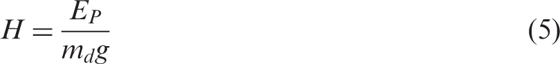
The required energy level was first estimated by using equation (4) and readjusted until visible damage was well observed. The required drop height was calculated using equations (4) and (5). Visible damage is vital for better analysis to be carried out on impact damage mechanism on the specimens. An energy level of around 27 to 28 J was chosen to be carried out on nine specimens, three for each configuration.

Results and discussions
Electrical continuity testing
Testing result of manufacture hybrid composites showed that there was no continuity in current flow across the hybrid composite (refer Figure 7). A piece of pure carbon laminate was manufactured with the same method and tested according to the same procedures. It was found that the carbon laminate is electrical conductive although there is a layer of epoxy resin sheltering above the first and last layer of carbon fibres in the laminate.
Electrical conductivity test conducted for hybrid composite panel.
Vibration test
Introduction
The experimental data were analysed and plotted in Figure 8. Figure 8(a) shows the resonance frequency of each hybrid composite configuration under excitation. Amplitude history output extracted from DEWEFRF 6.6 software is shown in Figure 8(b). Figure 8(c) shows the experimental data of percentage in structural damping for each hybrid composite configuration obtained from MODENT post-processing software.
Vibration test results: (a) amplitude vs. frequency, (b) amplitude decay curve and (c) percentage structural damping.
Amplitude history output
Results obtained from Figure 6(a) and (b) shows that the presence of high stiffness materials in the hybrid composite laminates increased natural frequency and reduced time required for energy/amplitude damping back to zero. The natural frequency of hybrid composites increases with the number or amount of high stiffness Kevlar. This indicated that adding the material of high stiffness in a laminate structure will delay the occurrence of resonance through increase of natural frequency. Higher the stiffness, the higher is the natural frequency. Higher external energy is required to stimulate the composite to vibrate in resonance. The amplitude time history obtained from DEWEFRF 6.6 illustrated the rate of decay of amplitude (energy) during vibration. For the case of
Percentage of structural damping
The results showed positive correlation with the analysis of resonance frequency and rate of decay of amplitude. It was found that
Three-point bending test
Stress–strain relationship and flexural strength
The stress–strain curve showed results of good correlation with stiffness of materials (refer Figure 9). The Stress–strain curves of hybrid composites under flexure. Flexural strength and modulus of hybrid composite laminates.

Flexural modulus
The experimental results showed that the amount or percentage content of Kevlar fibres has a proportional relationship with the tendency of composite laminate to resist bending. The more the amount of Kevlar fibres, the higher is the flexural modulus. The
FEA
The maximum displacement obtained from flexure test was set as boundary condition. It was found out that the continuum shell element used in this modelling generated inaccurate results for stress analysis due to large distortion in shell elements. The load-displacement for the models were analysed instead of stress-displacements.
The composite laminate undergoing flexural test is shown in Figure 11 while an example of the modulus correlation for experimental and FEA is shown in Figure 12. The FEA data from the linear/elastic portion were extracted and flexural modulus calculated from standard equations in ASTM standards. The flexural modulus calculated from FEA method were compared with values obtained via experimental method as shown in Figure 13. Results show that FEA calculations overestimated the value of flexural modulus. Flexural modulus of hybrid composites calculated from simulation load-displacement data are greater than the flexural modulus value obtained through experiment. The percentage of deviation of FEA results to experimental values for Laminate undergoing flexure load modelled in ABAQUS. Example of FEA flexural modulus correlation. Comparison of flexural modulus (FEA and experimental).


Low velocity impact test
Impact load response
The hybrid composite specimens were impacted with energy values ranging between 27 and 28 J obtained by fixing the height, which is expected to experience supercritical impact. Figure 14(a) presents the load-time response for various hybrid laminate configurations. Indeed the experimental results showed that the peak load coincided with the incipient damage load. The averaged peak load values of composite specimens were calculated from raw data obtained from the impulse data acquisition system. Peak load corresponds to the onset of material failure during an impact. The averaged peak load for Impact response of hybrid composites: (a) Load-time curve and (b) energy-time curve.
Energy absorption
Energy absorbed by the hybrid composite during penetration impact was analysed (refer Figure 14(b)). Energy absorbed was used to characterize the toughness of hybrid composites. In the definition of material science, toughness is the ability of the material to absorb energy and plastically deform without fracture. As shown in the figure above, the impact energy was first absorbed elastically by the composite specimen during elastic deformation in bending. Elastic energy,
Damage area
The damaged area of post-impact specimens was analysed (refer Figure 15). In total, three types of comparison were carried out. First, the delamination at the impacted surfaces for all three configurations was analysed. Next, a comparison was made in between (a) Impacted side of hybrid composite specimens and (b) bottom side of hybrid composite specimens.
The conditions at the impacted side of specimens are generally the same, having some delamination and fibre breakage in the dented region (refer Figure 15(a)). Some fibre breakage was observed in the glass and Kevlar layer. Carbon layer may have experienced fibre breakage but not found to be visible. The extent of delamination in the 0° direction at impacted side (compressive side) was found to be greater in configurations with more Kevlar layers. This may be due to the combination of delamination in the Kevlar and 0° carbon non-crimp fabric at the compressive side. Carbon and Kevlar fibres are excellent in tensile strength but weak in compression.
In general for the damage in the bottom side of the impacted specimens, the damaged area for
Conclusions
Electrically non-conductive hybrid composites have been manufactured successfully using RTM process. E-glass layer at the outermost layer provided electrical insulation to the composite structure. This was validated through continuity testing. Manufactured hybrid composite was also characterized through mechanical testing to determine the optimal configuration depending on the type of loading. Following are the main findings of the research:
Vibration test with SDOF analysis method showed that the percentage of structural damping and natural frequency of hybrid composite increased with the number of Kevlar layers. The presence of Kevlar fibres improved the damping properties of the hybrid composite structure. The The flexural strength and flexural modulus was found to have a proportional relationship with the amount of Kevlar fibres. The impact peak load of hybrid composites was found to be affected by total number of layers of fabrics. However, for the case of same number of fabric layers, increase of peak load was observed with the increase of Kevlar fibres and reduction of E-glass fibres. The absorbed energy was found to depend strongly on number of glass layers due to its ductile behaviour. More severe fibre breakage was observed at the bottom side of the specimen with the increase of E-glass fibres and reduction of Kevlar fibres.
Vibration and mechanical performances of hybrid composites.

The hybrid composites configuration are rated with Grade 1 (best) to Grade 3 according to their vibration, mechanical performances and post-impact damaged area. It is only comparable within these three configurations only. The
Footnotes
Declaration of Conflicting Interests
The author(s) declared no potential conflicts of interest with respect to the research, authorship, and/or publication of this article.
Funding
The author(s) disclosed receipt of the following financial support for the research, authorship, and/or publication of this article: The authors would like to acknowledge the financial support from Nanyang Technological University, Singapore.