
Abstract
High temperature three-dimensional (3D) braided seals are required for advanced hypersonic airframe applications to avoid a lot of hot air leaking into the internal structure. The gas permeation of 3D braided seals at room temperature was studied. According to Darcy’s Law, we present a computational model based on K-C equation and Kozeny theory for prediction. The model is combined with microstructure of the 3D four-directional braided seal and 3D five-directional braided seal, to predict the gas permeation as a function of fiber volume fraction, compression ratio, and pressure drop across the seal. The comparison showed that the predictions are in good agreement well with the experimental data. The 3D four-directional braided seal and 3D five-directional braided seal were fabricated and their gas permeation was measured in order to verify the prediction model.
Introduction
Heat seal is installed in the joint parts of the spacecraft, when the shuttle in the extreme thermal environment, which is used to reduce airflow. These seals are necessary to limit the ingestion of high temperature gases into the gaps between panels or in control surface locations. Incursion of high temperature gases into vulnerable areas could result in reduced vehicle stability or potentially even loss of the vehicle and crew [1,2]. X-51A Waverider hypersonic flight failed the first test just because the thermal seal between the rear of the fuel-cooled engine and its vehicle mounted nozzle was not as tight as it needed to be. This caused some of the hot gases that should have provided thrust to leak into the rear of the cruiser [3]. The study of air permeability in high temperature seal has been the key to the development of space vehicle.
A number of experimental studies have been conducted to understand the mechanical behaviors and gas permeation of high temperature seals. NASA Glenn Research Center (GRC) became involved in the development of high temperature structural seals in the late 1980s and early 1990s during the National Aerospace Plane (NASP) program [4]. Dunlap [5,6] showed that a system composed of monolithic silicon nitride wafers was an excellent candidate to meet the sealing needs of future hypersonic vehicles. But the ceramic wafers were brittle material, so they cannot be used in the corner. Current seals did not meet the demanding requirements of some application, so NASA Glenn Research Center developed the braided rope seals to overcome these shortfalls. Steinetz et al. [7,8] described the types of seals being developed and assessed the performance of seal. They presented leakage flow data under representative pressure, temperature, and scrubbing condition. It was feasible of the braided rope seals for both an industrial tube and turbine vane seal application. Cai et al. [9] and Mutharasan et al. [10] proposed an empirical leakage preload model to characterize the observed decrease with increasing preload and compared to experimental leakage measurements. But the braided rope seals may be eliminated with larger preload. Then a more flexible thermal barrier was developed. The baseline seal consisted of an Inconel X-750 spring tube stuffed with Saffil batting and over braided with two layers of Nextel 312 ceramic sleeving. Demange J, et al. [11] found resiliency improvements measured in the spring tube component translated into enhanced performance for the full construction seal. Unfortunately, these seals lost their resiliency and took on a large permanent set when they are compressed at high temperatures [1].
Three-dimensional (3D) braided preforms using high-performance fibers was receiving great attention as a result of a number of advantages, including through-thickness reinforcement, structural integrity, processability, and excellent transverse strength, which have been increasingly incorporated into aerospace and military [12–14]. Compliant seals require high temperature, low-leakage to mitigate thermal stresses and control between structures. For the use of thermal seal properties, a new type of thermal seal with 3D braided structure was introduced [15]. In this study, we develop a quantitative model to predict changes gas permeation of 3D braided seals with increasing preload. Then, we compare the predictions of that model to experiments. The model developed prediction of the gas permeation as a function of fiber diameter, fiber volume content, gas properties, specific surface of microstructure, and pressure drop across the seal. The purpose of this paper is to provide an analytic means of predicting the gas permeation through these braided structures and to determine quantitatively the relationship between gas permeation and the structure of the 3D braided seal.
Theory
In this study, the main steps in developing the model are to select appropriate variables to describe the permeability and specific surface of 3D braided seal.
On the basis of representative volume cells of 3D braided seal, we obtained the quantitative relationship between gas permeation and the pore structure of the seal, write the balance equation for these variables, and develop transport equations to describe the gas permeation.
Permeability
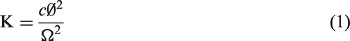
Permeability is an important property parameter of porous media. It represents the difficulty levels of fluid flowing through porous media with certain driving force. 3D braided preforms were braided with a number of fiber tows, which are formed through multidirectional yarns interlaced with each other, so it is a typical porous structure. Permeability is obtained by statistical method and determined by the geometry structure of pore media. A number of experimental studies have been conducted to establish a theory of linking the geometry structure of pore media and permeability. Among them Kozeny theory is most common [16]. It takes pore media as a bundle of parallel capillary tubes of the same size, which must have circular cross section. It is assumed that the fluid in this system is in a slow steady flow state and permeability is given as follows
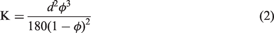
Another kind of empirical expression is used to calculate the absolute permeability of porous media, which is K-C (Kozeny–Carman) equation
Wittmann-Ténèze et al. [18] investigated the relationship between gas permeability and microstructure of porous media (porosity) under normal temperature and used the K-C equation described the mass transfer process. Although this study did not refer to the structural parameters of the material, the relationship between permeability and porosity was given. The different data showed that the evolution of the gas permeability with the porosity follows the Kozeny–Carman equation.
At present, there is no equation for the gas permeability of the 3D braided seal. Equation (1) clearly expresses that ϕ, Ω, and K are interrelated. But equation (2) does not show the relationship between the specific surface and the permeability. The 3D braiding seal is a typical porous structure. Different braided structures have different specific surface and their permeability are not the same. According to equation (1), the 3D braided seal of different structures with different specific surface characteristics, modified equation (2) to apply to 3D braided seal, which is given as follows

Specific surface and assumption
The specific surface, Ω is defined as the total surface area per unit volume of particles in porous media or internal surface area of the total pore per unit volume of particles in porous media [19]

Specific surface of porous media is a very important structural parameter in heat and mass transfer. It is related to the permeability of the porous material. Within a certain range, the specific surface of porous media become larger, the adsorption capacity of the fluid is greater, the permeability is lower.
This paper calculate specific surface of 3D braided preforms produced by the four-step 1 × 1 method. The topological structure of 3D braided preforms is determined by row and column track movements of yarn carriers on a machine bed [20]. Four steps of motion as one machine cycle are imposed to braid the tows, which move throughout the cross-section and are interlaced to form the structure. In this scale, the representative volume cells (RVC) structure of 3D braided preforms is a periodical cycle. In addition, the yarn cross sections of braiding yarns and axial yarns become complicated due to their mutual squeezing.
Chen et al. [20–22] have done a lot of analysis of microstructure about 3D braided preforms. On the basis of these analysis, combining the characteristics of the gas through 3D braided seal, the following assumption have been made of the geometrical representative volume cells structure of a braided seal.
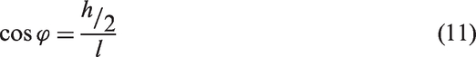
Multifilament braiding yarns are straight in the representative volume cells, whose cross-section is elliptical with major and minor radii, a and b, respectively. The braiding process is quite stable and the braided structure is uniform. All yarns in the braided preform have identical constituent material and size. The yarn packing factor is The interior RVC plays a major role in gas resistance, and hence it has been chosen to analyze the whole structure.
Specific surface of 3D four-directional braided seals
The four-step 1×1 braiding pattern of 3D four-directional braiding process are illustrated in Figure 1(a). After these four-steps, the yarn carriers on the machine bed return to the original pattern, completing one machine cycle and forming a pitch length of preform. According to the above braiding process, the orientation and the position of each yarn in the space can be defined, then the topological structure of interior RVC can be established (see Figure 1(b)). Figure 1(c) is real yarn cross section and Figure 1(d) is ideal shapes of braided yarn.
Detailed structural information of 3D four-directional braided composites: (a) yarn moment traces in x–y plane, (b) topological structure of interior RVC, (c) real yarn cross sections, and (d) ideal shapes of braided yarn.


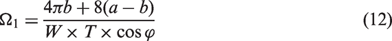
Combining equations (4) and (5–11), we expect the specific surface
Specific surface of 3D five-directional braiding seals
The four-step 1 × 1 braiding pattern of 3D five-directional braiding process are illustrated in Figure 1(a) [21]. The carriers on the machine bed are different from 3D four-direction. There are two carriers on the machine bed, one is braided yarn carrier and the other is axial yarn carrier. The braiding process is the same as 3D four-direction preform, the topological structure of interior RVC can also be established (see Figure 1(b)). Figure 1(c) is real yarn cross section [20], [23] and Figure 1(d) is ideal shapes of braided yarn.
Five-directional 3D braided seals contain the axial yarn and the braiding yarn. Similar to the 3D four-directional braiding process, a certain “jamming” action is imposed on all the yarns, which makes the yarns more or less closely intertwined. The cross-sectional dimension of braiding yarn is an elliptical and the axial yarn can be considered as quadrangle [24].


Combining equations (4), (9–11), and (13–16), we expect the specific surface

Gas permeation
Liquid into porous medium was usually modeled using Darcy’s law. Gas belongs to compressible fluid, if using Darcy’s law, it must satisfy two conditions: (1) gas flows is based on a continuum assumption in the flow, which is only applicable if the ratio of the mean free path of the molecules to aperture of porous media is less than 1. Under these conditions, the mass transfer mechanism of gas through porous media is viscous [25]. (2) The Reynolds number is less than 10. When the Reynolds number increases up to a critical value, which usually varies for different cases, the microscopic inertial effect becomes apparent, and the Darcy law is found to be inaccurate [26].
For 3D braided seals, the diameter of monofilament is greater than 9
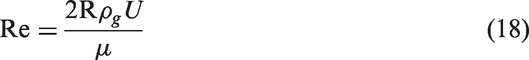
By calculation, we obtained the Re of air through 3D braided seals less than 10, so Darcy law is found to be accurate to calculate the gas permeation of 3D braided seals.
Gas permeation of 3D braided sealing strip
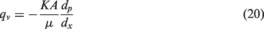
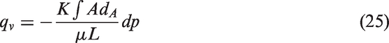
Figure 3 is schematic diagram of gas flow through the seal. Gas flow is regarded as a continuum assumption in the flow, so for this process, Darcy’s law can be expressed [19]
Schematic diagram of gas flow through the sealing strip.

Because the fluid is gas and flow horizontally, it can ignore the gravity effect. An improved equation is as follows
Both ends of the equation (19) are multiplied by
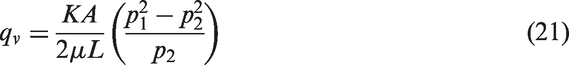
Combining equations (3) and (21), the permeation of gas through the 3D braided sealing strips can be expressed as

In this model, we consider cs value of 3D four-direction braided seal strips equals 1. So the gas permeation of 3D four-direction braided sealing strip can be expressed as
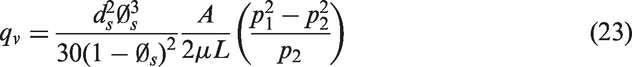
Because cs is a dimensionless constant only relating to specific surface of 3D braided seals, so the gas permeation of 3D five-direction braided seal strips can be expressed as
Gas permeation of 3D braided sealing ring
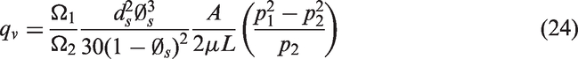
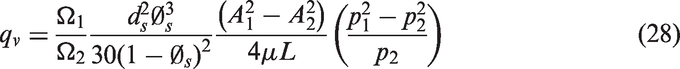
Figure 4 is schematic diagram of gas flow through the sealing ring. Because the cross-sectional area of air through the sealing ring becomes gradually larger along the radius direction, the gas permeation equation of sealing ring is
Schematic diagram of gas flow through the sealing ring.
Both ends of the equation (24) are multiplied by
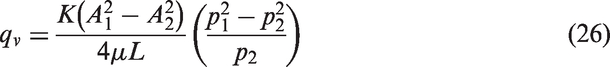
Combining equations (3) and (26), the permeation of gas through the 3D four-direction and five-direction braided sealing rings can be expressed as

Experimental
Braided seal specimen
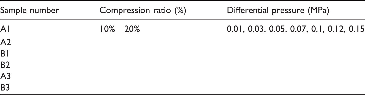
3D braiding seals were fabricated using the 3D braided machine at the Institute of Composite Materials of Tianjin Polytechnic University (China). Six seal specimens (Figure 5) were made using 190 tex quartz fiber bundles. The materials properties of yarns are summarized in Table 1 and specifications of test samples were labeled A1 (A1, A2, A3 is 3D four-direction structure) through B3 (B1. B2, B3 is 3D five-direction structure) in Table 2, which is used to calculate the gas permeation of 3D braided seals in the subsequent sections.
Specimen of 3D five-directional braided preforms (A is 3D four-direction, B is five-direction, and C is the sealing ring. Materials properties of yarns. Parameter tables of 3D braided seals.


Flow measurement
Since there are no definite standards of flow tests for 3D braided seal, the test procedures are conducted according to the standard of GB/T 25077-2010/ISO 9053:1991 and ASTM C522-03 (reapproved 2009). Flow test is carried out at room temperature, as shown schematically in Figure 6 [30]. Seal specimens were mounted in a specially developed test fixture, which were leak tested at various pressure conditions in the range of 0.01–0.15 MPa and different amounts of linear compression. Air flows through the gap between the cartridge and the cover plate, passes through the seal, and then flows out of the top of the fixture (Figure 5). A flow meter upstream of the flow fixture measures the amount of flow that passes through the test seal [31]. The flow meter has a range of 0–100 standard liters per minute (L/M) and accuracy of 1% of full scale. Test conditions and parameters are listed in Table 3.
Schematic of the flow fixture. (a) Flow fixture. (b) Isometric. (c) Cross section. Test conditions and parameters.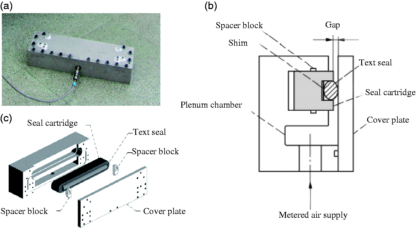
Results and discussion
Comparison of measured and predicted gas permeation
In Figures 7–10, typical gas permeation–pressure curve are plotted as a function of the difference compression for specimens A1, A2, B1, and B2 at pressures of 0.01–0.15 MPa. Both 3D four-direction braised seal and 3D five-direction braised seal showed a gradual increase with differential pressure increase from 0.01 to 0.15 MPa. Compared with A1, A2 and B1, B2, the gas permeation of the same structure seals decreased at the same pressure with increasing volume fraction due to decreasing porosity. However, compared with 3D five-direction braided seal, 3D four-direction braided seal exhibit lower gas permeation (Figures 8 and 10). Moreover, the volume fraction 50% of 3D four-directional braided seal shows the lowest gas permeation at the same pressure and compression. 3D four-direction braided seal showed better air tightness which may be attributed to the difference of the representative volume cells. 3D four-direction braided seal consists of braiding yarns, which are crisscross, and the internal yarns interwoven more closely to meet the compressive deformation under transverse compression, which making it more difficult for the air to flow around the fibers.
Seal A1 measured gas permeation compared to predictions. (a) Compression 10%. (b) Compression 20%. Seal A2 measured gas permeation compared to predictions. (a) Compression 10%. (b) Compression 20%. Seal B1 measured gas permeation compared to predictions. (a) Compression 10%. (b) Compression 20%. Seal B2 measured gas permeation compared to predictions. (a) Compression 10%. (b) Compression 20%


The predicted linear relationship between gas permeation and 3D braided seal parameters is indicative of the validity of the pressure dependency presented in equations (22) and (23). Both models predict the gas permeation reasonably well with the measured data over the full pressure range. At differential compression and pressure, the discrepancy between the measured and predicted gas permeation were only between 0.38 and 10.12, even though the overall gas permeation differed by a factor of 0.11.
In the equations (21) and (22), we can found the gas permeation decreased with the increasing volume fraction and specific surface under the same temperature and yarn diameter. Models predict the gas permeation reasonably well with the measured data.
Potential sources of modeling discrepancy
A potential source of the discrepancy between the measured and predicted gas permeation is the specific surface, especially the theoretical data and experimental data of the five-directional preforms with the increase of the pressure drop. With the compression increasing, the fibers are urged closer to one another and the adjacent surface making real yarn cross sections more complex. The choice of porosity has a considerable effect on the predicted gas permeation. In this model, selection of the porosity is based on the volume fraction. For example, since in equations (22) and (23), increasing it from 0.5 to 0.51 increases the predicted gas permeation by 10%. As improved measured values of porosity become available, it is expected that the porosity could more accurate and narrow errors.
Summary and conclusion
Both models are based on the Kozeny–Carman relations for flow through porous media, which predict the gas permeation reasonably well with the measured data. Basing on the findings from the comparison between measured and predicted gas permeation, the following results were obtained:
Increasing volume fraction and compression, the gas permeation will be decreased. When the volume fraction of fiber was increased, the volumetric flow of gas decreased by an average of 7.91 M/L at different pressure difference, and decreased by 12.42 M/L at 0.15 MPa. The influence of the fiber volume content on the gas permeation is more significant. The gas permeation of 3D four-direction braided seal is lower comparing with 3D five-direction. The volume fraction of 50% of 3D four-direction braided seals shows the lowest gas permeation at the same pressure and compression. The average minimum volume flow is 29.2 M/L. With the compression and volume fraction increasing, model predicted values reasonably well with the measured data. The equations (23) and (24) can be used to predict gas permeation of 3D braided seal at different compression and pressure, which can be used as the input model of the sealing structure parameters. By changing the parameters of the 3D seal structure, the gas permeation of 3D braided seal can be reduced in unit time and pressure, which provides the some structural design basis for the braided seal.
Footnotes
Declaration of Conflicting Interests
The author(s) declared no potential conflicts of interest with respect to the research, authorship, and/or publication of this article.
Funding
The author(s) disclosed receipt of the following financial support for the research, authorship, and/or publication of this article: supported by Seed Foundation of Tianjin University (No.15ZCZDGX00340).