
Abstract
This paper deals with the fracture failure analysis on plain woven laminated fabrics used in stratospheric airship structures. A series of uniaxial tensile and central slit tearing tests were carefully conducted on bias specimens, and the corresponding tensile and tearing properties, including failure mechanisms and material strengths, of a laminated fabric were discussed. Results show that laminated fabrics are typical direction-depended materials, and their failure characteristics vary greatly with the bias angles. Typical tearing stress–displacement curves of the laminated fabric could be defined as four characteristic regions: a co-deformation region, a yarn extension region (or shear deformation region), a plateau region, and a post peak region. Among bias specimens, there are many obvious differences in tearing behaviors in terms of maximum displacement, damage mode, curve slope, and number of stress peaks, which could be attributed to the material orthotropy and different failure mechanism of constituent materials. Unlike results of tensile strength, there is a W-shaped relationship between tearing strength and off-axis angle, with a local strength peak at 45° angle. Based on the Tsai-hill criterion, a new tearing strength criterion consisting of two parts, including a U-shaped and an inverted V-shaped part, is proposed for this laminated fabric. Comparisons between the experimental and calculated results for the laminated fabric are performed, and the strong agreements demonstrate that the proposed criterion is feasible and accurate.
Introduction
There has been a considerable interest in stratospheric non-rigid airships as a cost effective alternative to earth orbit satellites for telecommunication and science observation. Due to its greatly expected usage, NASA, ESA, JAXA, etc. have developed plans to utilize stratospheric airships (SSAs) [1–3]. The envelope of the non-rigid airship structure is made of ultra-light and high strength laminated fabrics [3]. The laminated fabrics provide structural strength for the system and act as the primary barrier between the outside air and lifting gas. Therefore, the laminated fabrics have attracted widespread attentions due to its importance in SSAs manufacturing [4,5].
Most known failures of fabrics have been caused by tear propagation, which is known to be the most common failure mode for fabrics [6]. The issue is particularly important in SSA structures, where rapid tear propagation initiating at sites of local damage or stress concentration is accompanied by a hazardous explosive release of compressed air. For the SSA structures, a tear or slit in laminated fabrics may lead to the material fracture, and even a collapse of the major airship structures under some extreme conditions, e.g. low pressure of the stratosphere, ozone oxidation, and high-low cyclic temperatures. Therefore, for the purpose of maximizing damage tolerance and preventing catastrophic tear propagation, it is imperative to investigate tearing mechanism of laminated fabrics used in the SSA structures.
The studying of tear propagation is an important subject due to its use in industrial applications. For instance, Krook and Fox [7] already discussed in 1945 the tongue tearing behaviors and described the del-shaped opening observed in the tearing damage. In the last several decades, this topic has received even more attention due to the increasing use of composite materials. Several kinds of tear methods are proposed and used to study the tearing behaviors of dry fabrics and coated (or laminated) fabrics. Some are in plane, such as trapezoidal tear method [8–12], central slit tear method [13–16], single edge notch tear method [17] and wing-shaped tear method [18,19], while other are out of plane, such as tongue tear method [20–23] and lounge-shaped tear method [18]. To date, the methods most widely used in tearing investigations of fabrics are the trapezoidal, central slit, and tongue tear methods, which have been adopted by some design code or guide [24,25]. The sample configurations of these tearing test methods can be found in Forster and Mollaert [25], Ennouri et al. [26], and Huntington [27].
The trapezoidal tear method forming the basis of most design norms [25] has been studied extensively. Hager et al. [8], Turl [9], Chu et al. [10], Wang et al. [11], and Wang [12] conducted trapezoidal tearing tests, and some of them proposed analytical models to study the fracture failure and tearing strengths of the fabric materials. According to the results from their works, the tearing strength of a fabric material is dependent mainly on the weave texture, geometry of specimens, weaving density, elastic modulus, and breaking strength of the yarns.
As an out of plane method, tongue tear method was originally applied to characterize tearing properties of fabrics in the garments industry. Tongue tearing behaviors of woven fabrics have also been investigated by many researchers through experimental and analytical approaches. For instance, Teixeira et al. [20] and Scelzo et al. [21] analyzed the contributions of structural parameters, including yarn type, weave pattern and weave structure, to the tongue tearing resistance of woven fabrics. Zhong et al. [22] employed a stochastic approach, using the Ising model combined with the Monte Carlo simulation, to study the tongue tearing behaviors of coated fabrics. The theoretical model was effective to predict the mechanical characteristics of heterogeneous materials. Lately, Wang et al. [23] investigated the tongue-tearing damage of woven fabrics from an FEA approach at the microstructure level. The friction coefficient, fabric construction, and weaving density were found to be the main factors influencing the tongue tearing strength and tearing load–displacement curves of woven fabrics.
For the central slit tear method, several investigations have been conducted on dry fabrics, coated, or laminated fabrics. Godfrey and Rossettos [14] and Godfrey et al. [15] proposed a micromechanical model to predict the onset of tear propagation at slits in biaxially stressed uncoated and coated woven fabrics. The model was shown to capture the onset of tearing in these fabrics quite well over a range of slit lengths. Bigaud et al. [16] experimentally investigated the tear propagation behavior of coated fabrics. They discussed the effects of initial slit length, slit orientation, and coating material on the tear propagation, and they observed two failure modes (brittle and progressive) depending on the initial slit length, its orientation and the loading ratio applied in warp and weft directions. Maekawa et al. [13] carried out biaxial central slit tearing tests and pressurized cylinder tests to obtain the tearing strength of an airship’s envelope material. Empirical formulas of the tearing strength, such as Thiele’s empirical equation and stress field consideration, were evaluated to be applicable to the Zylon envelope material. Chen et al. [28] and Chen and Chen [29] tested central slit tearing behaviors of a laminated fabric with different slit lengths under uniaxial and biaxial tensile loads and proposed an analytical model to evaluate the uniaxial tearing strength of the laminated fabric with a slit oriented at 0°.
Apart from the aforementioned work [8–16,20–23], some other studies [17,30,31] have reported on less frequently-used tear methods. Topping [30] conducted comparisons among four different theories predicting the burst strength of longitudinally slit pressurized fabric cylinders. Burst strengths were found to be independent of the width of the slit and the cylinder length in the ranges investigated. Liu et al. [17] developed a physical model to analyze the tearing strength of a laminated fabric with an initial single edge notch. Bai et al. [31] evaluated the notch sensitivity and tearing resistance of the Kevlar-PWF-reinforced TPU film applied in high altitude balloon.
Differing types and sizes of local flaws, damages, or tears have been found to produce different tearing behaviors, including tearing strength or tearing force, and tear propagation properties. Therefore, it is necessary to select a suitable tear method to determine the tearing properties of the membranes, which should then be used for design purpose. Unfortunately, most of the common tear methods (the trapezoidal tear method, tongue tear method, and wing-shaped tear method) are typically intended for the garments industry rather than as appropriate methods for structural fabrics. In particular, the tongue tearing test is inappropriate [25].
As for the laminated fabrics used in airships, there have also been studies focusing on tensile properties, temperature dependency, reinforcing methods of an opening, and long term weathering characteristics of envelope fabrics. Komatsu et al. [5] evaluated the bonded strength of some high-specific-strength laminated fabric for stratospheric platform (SPF) airships, focusing on the high-temperature tensile strength and creep properties because the strength of the envelope structure was determined by the joint shear strength. Wanggu et al. [3] studied the uniaxial tensile characterization of a laminated fabric developed for SSA envelopes. They performed uniaxial tests in the thermal chamber at low, room, and high temperatures to investigate the temperature dependency. Nakadate et al. [32,33] investigated the reinforcing methods of an opening on two kinds of laminated Zylon® fabrics for SPF airships and studied the long term weathering characteristic of those laminated fabrics.
According to the aforementioned literatures, an experimental investigation is the main way to determine tearing behaviors of the woven fabrics and the data are often used as a standard for verifying the calculated results of the corresponding analytical or FEA models. Therefore, those tearing tests which can simulate the actual tear propagations in SSA structures are the most direct and effective means to determine tearing mechanism of laminated fabrics. Among all the tear methods, the central slit tear method is considered to obtain closer tearing characteristics of the laminated fabrics to the engineering practice than the tongue, trapezoid, and wing tear methods in terms of the tension distribution and slit-opening shape. Thus, design criteria for non-rigid airships, such as FAA-P-8110-2 Airship Design Criteria [24], specify the method to measure the tearing strength of an envelope material (almost all of them are laminated fabrics) through central slit tearing tests.
Proper design and analysis of membrane structures require a fundamental understanding of their mechanical behaviors [34], including the tear propagation, damage morphology and tearing mechanism, which represent the simplest, but most important, mechanical behaviors of laminated fabrics. To the best of our knowledge, there are not enough studies focusing on the central slit tearing behaviors such as tearing stress–displacement relationships, tearing strength criterion, and damage morphology of laminated fabrics.
Moreover, as we all know, the woven fabrics, including laminated fabrics, are highly anisotropic, so that their mechanical properties, including tensile/tearing behaviors and strengths, are inevitably a function of direction. However, few investigations have been conducted on central slit tearing behaviors of laminated fabrics influenced by different off-axial angles. Definitely, more researches are required to figure out how and to what extent the anisotropy and off-axis angle affect the tearing behaviors and tearing strength. The findings would be of significant interest to the understanding on the tearing mechanism of laminated fabrics and to the structural safety assessment of membrane structures.
Additionally, the tearing strength criterion deals with the failure of materials with slits under complex stress states and is an important foundation for theoretical research and engineering application. Several fracture models have been proposed to predict tearing strengths of woven-fabrics under uniaxial loads [13,30]. However, all these fracture models apply only to on-axial tearing specimens and the tearing strength of off-axial specimen cannot be predicted by these models. Nowadays, as for the tensile strength, there have been several classical strength criteria for predictions of the bias tensile strength of fabrics, including Tsai-hill criterion, Yeh-Stratton criterion, Hashin criterion, and Zhang criterion [35–38]. All these criteria for tensile strength are popular macroscopic criteria due to their operationally simple expressions, and most of them could present relatively accurate predictions for engineering design. Besides, the tearing characteristics of woven composites have close relations with their tensile properties, and the tearing behaviors and strengths of the woven composites are mainly determined by their tensile behaviors and tensile strengths [28]. There are some researchers [39] who concluded that for a specified range of load ratios, the uniaxial tensile tests can describe the behavior of certain coated fabric under biaxial tests. For this study, the uniaxial tensile tests could provide enough information of mechanical properties for the tearing analysis. So in order to achieve a better understanding on tear mechanism and a feasible bias tearing strength criterion for laminated fabrics, it is necessary to conduct not only the tearing study but also the uniaxial tensile research of the same woven fabrics.
This paper presents an experimental study on bias tensile and tearing properties of the typical airship envelope fabric Uretek3216LV under uniaxial tensile loads. The aim of this study is to expose the fracture failure characteristics and bias tearing mechanism of laminated fabrics. Initially, uniaxial tensile and tearing tests are carefully carried out on the laminated fabric, including on-axial and off-axial tests, and the corresponding test data are obtained. Afterward, the failure behaviors, characteristics of load-displacement curves and material strengths of on-axial and off-axial samples in tensile and tearing tests are described in detail, and the effects of yarn orientation, i.e. off-axis angle of yarn, on the failure mechanism, tearing propagation and material strength of the laminated fabric are analyzed. Finally, a modified tearing strength criterion is proposed based on the Tsai-hill criterion, and the predictions are then compared with the experimental data, along with discussions on some key issues. It is hoped that this investigation could provide a good understanding on fracture failure behaviors, direction-dependence, and central slit tearing mechanism of laminated fabrics.
Material and methods
Materials
The envelope of SSAs is made of laminated membrane materials. In addition to containing the lifting helium gas, it is also required to protect the airship from ultraviolet (UV) and visible radiation and environmental degradation, and sustain external forces such as buoyancy, aerodynamic, and inertia forces. Different materials are laminated to realize each functional requirement of the envelope. For SSAs, the envelope material must exhibit low gas permeability, high environmental resistance, high strength-to-weight ratio, and excellent tear resistance. Excellent environmental resistance protects the system from environmental degradation, which ultimately leads to longer system life and low system maintenance. A low gas transmission rate through the hull material is required to minimize lift loss and maximize on station time. The envelope material must also be lightweight to minimize envelope size and weight, while exhibiting sufficient strength to overcome aerodynamic stresses and the pressure differential acting on the envelope. Furthermore, high tear resistance is necessary to maximize damage tolerance and prevent catastrophic tear propagation which is the focus of this study. In addition, the material must be structurally bondable on one side or both sides.
In order to meet the above mentioned requirements, the typical envelope material layout is shown in Figure 1(a). The envelope material generally consists of components, which permit tailoring of the various material properties to optimize the resulting balance between tensile strength, service life, weight, gas retention, and flexibility [3]. In this paper, the envelope material Uretek3216LV shown in Figure 1(b) consists of five functional layers, including the wearable layer, the U-ultraviolet layer, the structural layer, the gas retention layer, and the sealing layer (shown in Figure 1a).
The envelope materials. (a) Typical envelope fabrics layout and (b) macro morphology.
The structural layer is composed of Vectran fiber plain weave fabric. The plain weave pattern is shown in Figure 1(a). The high-performance thermoplastic multi-filament yarn is spun from Vectran® liquid crystal polymer (LCP). Vectran® fiber exhibits high strength to weight ratio, low creep, low moisture regain, improved hydrolysis resistance, and excellent cut resistance. The overall properties make the Vectran® fiber a good choice for SSA structures.
Specifications of the laminated fabric.

Tedlar PVF film is selected as the helium barrier and the UV radiation protection. It is laminated to the structural layer by polyurethane adhesive matrix. The Tedlar film is well known for its excellent resistance to weathering, outstanding mechanical properties, very good UV protection capability, and inertness toward a wide variety of chemicals, solvents, and staining agents [3].
Specimens
In accordance to the standard of ISO1421-1998, the strip specimen for uniaxial tensile tests was made to be 200 ± 1 mm (effective length) by 50 ± 0.5 mm (width). To test the tensile behaviors of laminated fabrics in different directions, seven groups of specimens were prepared in such a way that the weft direction was biased 0°, 15°, 30°, 45°, 60°, 75° and 90° angle, respectively, against the loading direction. For each bias direction, five specimens were prepared.
The uniaxial tearing tests were performed on rectangular specimens with a central slit. The photograph and geometrical dimension of tested samples which is based on the ‘airship design criteria’ FAA-P-8110-2 [24] are illustrated in Figure 2. The shadow zones in Figure 2(b) represent clamping areas in the upper and lower jaws, and the effective area of the specimen is 76.2 × 101.6 mm2. As shown in Figure 2(b), the slit was made by striking the fabric with a utility knife at an angle of 90° to the loading direction, and the off-axial samples were prepared by cutting the fabrics at the off-axis angles of 0°, 15°, 30°, 45°, 60°, 75°, and 90° from the warp direction. In other words, the tests of off-axis angles of 0° and 90° indicate the on-axial tearing tests in weft and warp directions, respectively.
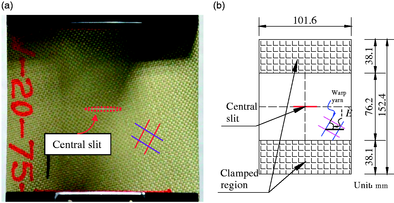
The specimen of the central slit tearing tests: (a) photograph of the specimen and (b) geometrical dimension (mm).
Layout of the experimental protocol.

Testing process
The uniaxial tensile tests were carried out using the computer operated strength testing machine ZWICK/ROELL-Z100 (Figure 3) in laboratory. The load was recorded by a 50 kN load cell and the strain was measured by a 50 mm grip extensometer (shown in Figure 3). Laminated woven textile has undulation on its surfaces due to the fiber architecture, which makes the use of strain-gauges impractical for strain measurements. In addition, the inherent large deformation of the envelope material gives another advantage of the use of the extensometer.
The ZWICK/ROELL-Z100 tester.
The uniaxial tearing tests were carried out on MINEBEA CHA-20 tester. The tensile speed for all tests was set to 100 mm/min according to the MSAJ/M-03 [41]. The initial tearing and the tear propagation of the specimens with different slit lengths were observed using a camera device.
Due to the existence of a central slit, the strain is uneven in the center of the specimen, or in the area near the slit. It is difficult to measure the representative strain of the sample. What’s more, in this study, the main purpose of the tearing tests is to determine the relationship between the tearing strength and off-axis angle. Hence, the tearing tests are carried out without extensometer. However, for the uniaxial tensile tests, as we all know, the stress distribution in the sample presents a uniform strain area in the central part of the specimen. The strain measured within this area presents a considerable increase in the level of reliability, and a more accurate correlation with the estimated stress in that area. Therefore, the tensile tests are carried out with the extensometer to obtain the proper stress–strain curves of the uniaxial tensile tests.
Environmental conditions
All tests were done at a relative humidity of 65 ± 4.0% and a temperature of 20 ± 2.0℃ according to the ISO 139-2005 standard [42].
Results and discussions
Tensile properties
Off-axial tensile behaviors
As shown in Figure 4, this material is typically orthotropic and the tensile behaviors depend strongly on the yarn orientation angle. The statistical results of off-axial tests are shown in Table 3. With the bias angle increasing, the tensile strength and modulus gradually decrease, while the breaking strain increases. The on-axial tensile strength, i.e. the strength in the direction parallel to yarn orientations, is the highest, and the breaking strain is the lowest. In the direction of 45°, the tensile strength is the lowest, but the breaking strain is the highest.
Tensile behaviors of off-axial samples. Statistical results of tensile tests.

The mechanical properties of laminated fabrics, such as stiffness, deformation, and strength, are strongly determined by the weave parameters (weave geometry, yarn spacing, yarn crimp, and yarn orientation) and the inherent material properties of yarns and other laminated layers. These different results of the tensile stress–strain curves in the two principal directions, i.e. the warp and weft directions, should be attributed to the inherent unbalanced structure of the laminated fabric resulting from the production of the woven fabric and laminating process [34,43,44]. During the material manufacturing process, the warp yarns are often pre-tensioned and the weft yarns are winded alternately around the warp yarns, and therefore the initial waviness of the warp yarns is much lower than that of the weft yarns. Hence, it is unavoidable to observe the significant differences between the tensile behaviors of warp and weft directions, just as shown in Table 3 and Figure 4. In addition, there are also some differences between the results of a pair of ‘symmetrical’ bias angles, such as 15° and 75°. These differences should also be attributed to the inherent unbalanced structure of the laminated fabrics, where both the yarn crimp and yarn spacing in weft direction are much higher than the corresponding value in warp direction [29,43,45–47].
As for the failure process, take as an example off-axis angle 45° as shown by Figure 5, there are three phases in the failure process of the laminated fabric, including fracture of several yarns, propagation of damage, and complete failure. All three phases are related with the mechanical properties of yarns, substrates, and interfaces. The laminated fabrics are composed of relatively brittle yarns with high strength, and few brittle yarns may fracture first in the low-stress phase. Once the yarns fracture, the yarn stress near the end of fracture crack reduces to zero and the deformation energy is released. As the bonding between yarns and adhesives could prevent the contraction of the fracture end of yarns, stress concentration starts to occur in the adjacent interface and adjacent laminated films, and then the released stress mentioned above is transferred to adjacent yarns, leading to ‘overstress’ of the adjacent yarns [35]. When the overstress approaches the ultimate strength of the yarns, the adjacent yarns will fracture and the damage starts to propagate (the second phase). After the second phase mentioned above, as the damage propagates, more and more principal yarns rupture. Moreover, the tensile stress of the specimen plunges to zero immediately after the peak, without any fluctuations prior to reaching the failure of the whole specimen (see Figure 4). The reason for this is that the failure process in the laminated fabric is very sudden with a rapid propagation across the center section of the specimen, and most of principal yarns often fracture simultaneously during the tests. It should be noted that, for the off-axial samples, due to the high shear deformation, the yarn–adhesive interface debonding occurs gradually and produces some partially intact interfaces, and then some of broken yarns or incomplete yarns could be pulled out against the frictional stress along the debonding interfaces. Therefore, for the off-axial samples, especially for the angle of 45°, at the last stage of a tensile test, the yarns in the last surviving zone are damaged not so much in a rupture manner as in a pullout manner (see Figure 5c), which is similar to the phenomenon of tearing tests obtained in Chen et al. [28].
Three phases in the tensile failure process of the laminated fabric: (a) fracture of several yarns; (b) propagation of damage; and (c) complete failure.
Figure 6 shows the fracture configurations of specimens for off-axial tensile tests. Three types of failure modes could be observed in Figure 6, namely pure tensile failure (yarn fracture), pure shear failure (yarn pullout), and mixed failure of tensile and shear. The propagation always happens parallel or perpendicular to the principal yarn directions, which is in line with the results of previous studies [35,37,44]. The pure tensile failure takes place in on-axial specimens, i.e. off-axis angle θ = 0° or θ = 90°, in which the damage propagation is perpendicular to the loading direction. During the tests, part of principal yarns, i.e. the yarns to resist most of the tensile forces, first rupture and the unloading will be transferred to the adjacent yarns with the aids of the secondary yarns and other laminated layers which can deliver the shear stress to other principal yarns. Due to the high adhesive strength, both crossover point slip and yarn–adhesive interface debonding only occur in a very small region near the ends of fractured yarns. As the principal yarns are difficult to be pulled out from the adhesives, most of them fracture, and therefore this failure mode could be named ‘yarn fracture’ [37].
Failure modes of bias samples: (a) yarn fracture; (b) mixed failure; and (c) yarn pullout.
A typical pure shear failure is shown in the specimen of θ = 45°. Under pure shear stress, yarns with fairly large debonded lengths are observed to be drawn out from the adhesives. Failure happens at the interface between the yarns and adhesives. The mixed failure takes place in the specimens other than those mentioned, particularly when θ = 15° or θ = 75°. The most obvious feature of the mixed failure is that a part of yarns is pulled out from the adhesives and the remaining yarns break at the their tensile strength.
In the bias specimens, there are two types of yarns, including complete ones and incomplete ones. With bias angle increasing, the number of incomplete yarns increases, while the number of complete ones decreases. Especially for the samples of θ = 45° angle, when loaded, no yarn is held by both ends, so that all the yarns (belonging to incomplete type) build up stress entirely via yarn–yarn friction and yarn–adhesive cohesive force [15,48]. As a result, only the yarns with enough embedded length can reach the stress level high enough to break, whereas the shorter yarns resulting from yarn fracture or other factors (referring to the incomplete yarns mainly) can be pulled out probably, contributing much less toward material strength [48]. From Figure 6, due to high shear force, the incomplete yarns are easily pulled out and then the failure mode changes from ‘yarn fracture’ to ‘mixed failure of tensile and shear’, and then to ‘yarn pullout’, i.e. ‘pure shear’ of angle 45°. Compared with the on-axial specimens, the number of pulled-out yarns in bias specimens increases and the number of fractured ones decreases, resulting in a relatively higher strain at break and a lower tensile strength. Specifically, when the bias angle increases from 0° to 45°, the strain at break increases by 26.5 mm and the strength decrease by 47.8 kN/m, about 390% and 55.4% of the corresponding average values of the on-axial specimens, respectively. The main reason is that the shear deformation gradually becomes the dominant factor and the interaction of tensile stress and shear stress is increasingly obvious with the increase of the bias angle, which could exert negative effects on the yarn–adhesive bonding.
Off-axial tensile strength criteria
The strength and failure mechanisms of composites are a complicate issue, which is associated with plenty of effecting factors, such as the mechanical properties of their constitutive materials, loading conditions, environment, and specimen’s geometry, etc. Strength criteria deal with the yield or failure of materials under a complex stress state. It is of great significance in theoretical study and engineering application, and is also very important for the effective utilization of the materials. Especially for the laminated fabrics, whose complex weave structures and multiple components lead to complex mechanical characteristics, the accurate and operational simple strength criteria are essential for practical engineering and the numerical simulation. The main intent of a feasible criterion is to predict the material strength under different stress states by knowing the basic material properties. The accuracy of a failure criterion can be validated only through the experimental tests. Due to the lack of sufficient experimental data of the laminated fabrics, although there are some existing failure criteria for composites [35], a validation study is worthwhile for the strength prediction of laminated plain woven fabrics.
In the existing failure criteria for composites, the Tsai-hill criterion is the most popular one for its concise expression and general applicability [35–37]. For the bias tensile strength, Tsai-hill criterion can be expressed as follows [44]:


Once X, Y and S are known, the relationship between Comparison of test data and predictions by the Tsai-hill criterion.
Tearing properties
Failure performance and tearing propagation
Similarities
Typical tearing damage morphologies are shown in Figures 8 and 9. Comparing these images in Figure 8(a) to (c) shows that there are many similarities in the failure performance and tearing propagation of the studied materials. First, as the load increases, the initial slit progressively takes an elliptic shape and the inelastic deformation and yarn slippage start to occur in the vicinity of slit tips. These increasing deformation and slippage could lead to the formation of large deformation regions bounded by an ellipse shown in Figures 8 and 9.
Typical tear propagation processes of on-axial (a) and off-axial samples (b). Schematic drawings of typical damage modes of the tearing specimens: (a) line-shaped opening; (b) Z-shaped opening; and (c) parallelograms-shaped opening.

Second, as shown in Figures 8 and 9, with the increasing of the uniaxial tensile force, two local tearing delta zones, i.e. the stress concentration regions, in which load bearing yarns have been pulled out of the adhesives by the concentrated tensile stresses, will take shape in the large defamation regions. The progressive delta zone of the tear tip develops gradually and the load bearing yarns break one by one at the tear tip. As shown in Figure 8, the failure of load bearing yarns in the delta zones is mainly due to direct tensile fracture. Here, the yarns in the delta zones can be generally divided into two categories: the principal and secondary yarns. Specifically, the load bearing yarns are the principal yarns and the non-load bearing yarns or less important yarns belong to the secondary ones. As the load increases, slippage on the principal yarns becomes more and more difficult, and thus the load is progressively delivered to the secondary yarns. The load transferred by the secondary yarns or other laminated layers (including adhesives) is delivered to other principal yarns again which are beyond the first intact yarn in the delta zone. And therefore, the pulled-out length of adjacent principal yarns increases and then the size of the delta zone is enlarged. As the load builds up further, some of the principal yarns fail once more and again yarns slip by each other to produce a new delta zone, and so on, in a cycle, until the failure extends over the length tested. For the uniaxial tests, in fact, the local delta zone is the symptom of the approaching tearing in the laminated fabric.
Differences
Nevertheless, some differences still exist between the tearing specimens with different slit parameters or yarn orientations.
The most significant is the slit-opening shapes due to the rotation of slit or yarns. As shown in Figure 9, the uniaxial tearing of the laminated fabric could produce three kinds of appearance in terms of the orientation of the tear: line-shaped, Z-shaped, and parallelograms-shaped opening. Specifically, for on-axial specimens, a slit could result in a line-shaped opening or a Z-shaped opening depending on their slit orientation [29], whereas, for off-axial specimens, their slits could form parallelogram-shaped openings.
Another key difference lies in the area and shape of the deboned regions. The surface of the laminated fabrics can be divided into three kinds of regions: perfect adhesion, partial debonding, and total debonding. In the perfect adhesion region, which corresponds primarily to most of the specimen’s surface except the area of the large deformation zones and delta zones shown in Figure 9, the composite behaves as a undamaged, elastic material, and the laminated film and yarns are elongated together. In the partial debonding region or the large deformation zones (indicated by the dark ovals in Figure 9), yarn–adhesive interface debonding and rupture of some filaments of yarns take place in the stress concentration area due to the defects and curvatures of the filaments assembling the yarns [28]. In these partial debonding regions, inelastic or even plastic deformation occurs in the yarns and other laminated layers, which indicates that the tearing probably will happen during the tests. As above existing debonding and slippage may reduce the barrier for yarn pullout, many yarns are pulled out in the tearing delta zone and the vicinity of the slit tips (the area indicated by ‘yarn pullout’ in Figure 9c). The tearing delta zone and the ‘yarn pullout’ area constitute the total debonding region. The Z-shaped opening (Figure 9b from the reference [29]) shows larger partial debonding regions, i.e. the large deformation zones, than the line-shaped opening. Among the three kinds of slit appearances, the parallelogram-shaped opening (Figure 9c) gives the largest total and partial debonding regions, and is the only kind that produces large area of yarn pullout. What’s more, for the Z-shaped and line-shaped samples (Figure 9a and b), the slit propagates simultaneously in the structural layer and other laminated layers, and the slit openings of the yarns and laminated layers coincide with each other. However, for the parallelogram-shaped samples (Figure 9c), the slit openings of the yarns and other laminated layers do not coincide with each other, which can be attributed to the occurrence of the yarn pullout region (see Figure 9c).
According to Bigaud et al. [16] and Chen and Chen [29], the failure mode and the slit propagation direction can be mainly decided by these factors as follows:
Slit equivalent length (related to the effective length and orientation), Loading ratios, Mechanical properties of the yarns in both directions, The orthotropy of the material.
Besides the factors mentioned above, the tearing failure of the laminated fabrics possibly involves a variety of factors: yarn orientation, specimen size and geometry, displacement versus load control, compliance of test fixture and test machine, etc. For the central tearing method, both the dimension of specimen and dimension of slit length directly affect the stress distributions in the vicinity of slit tips, and thereby affect tearing behaviors of the material. For a given specimen, the tearing resistance of the material will decrease significantly with the increasing ratio of the initial slit length over the width of the specimen. Although, some kinds of specimens have been used to determine the tearing behaviors of fabric materials, there has not been a widely accepted specimen to accurately estimate the tearing behaviors of fabric materials. In the authors’ opinion, a suitable specimen with appropriate dimensions and slit length which can simulate the real tear propagation in fabric materials is needed for the fabric structures’ design and should be investigated in the future work.
As off-axial specimens could show great shear deformation and large area of yarn pullout, when the slit starts to propagate, these shear deformation and yarn pullout could absorb more energy and reduce the stress concentration in the yarns at the slit tip and, therefore, during the tests, most of the specimens failed in a progressive mode, and they exhibited progressive damages of the yarns and other laminated layers before the failure of these specimens.
Figure 10 shows the typical damage modes of tearing specimens with different slit orientations and yarn orientations. Here, the results shown in Figure 10(a) is a summary of on-axial tearing tests with different slit orientations [29]. It is obvious from Figure 10(a) that for uniaxial tearing tests, whatever the orientation of the initial slit is, the propagation is always perpendicular to the tensile loading direction. Consequently, only lengthways yarns are broken, and the path is thus as energetically economical as possible. Unlike the slit orientation, the off-axis angle of yarns could affect the slit propagation direction of the laminated fabric significantly. As shown in Figure 10(b), with the increase of off-axis angle changing from 0° to 90°, the slit propagation angle, which is the angle between the loading direction and slit propagation direction, first decreases and then increases. As the local delta zone is the symptom of the approaching tearing in the laminated fabric, the variation of the slit propagation angle could be attributed to the rotation of principle yarns in the local delta zone.
Schematic drawings of typical damage modes of the tearing specimens with different slit orientations (a) and off-axis angles (b).
Due to the yarn rotation, the contributions to bearing capacity of warp and weft yarns vary with the bias angle. For the specimens of bias angle 45°, the yarns in two directions can take joint action to offer the resistance to tear propagation. During the tearing propagation, not only the warp yarns but also the weft yarns are pulled out or broken by the combined tension and shear, and therefore, the specimens of bias angle 45° could exert more load carrying capacity of the material than some other angles. The effects of the yarn rotation on tearing strengths will be discussed later.
Tearing behaviors affected by off-axis angles
The tearing stress–displacement curves of different bias specimens with a slit length of 20 mm (Figure 11) are chosen for detailed study. According to Figure 11, the studied laminated fabric is typically orthotropic and the tearing behaviors depend strongly on the yarn orientations. The peak stresses (or tearing strengths) and slopes of tearing stress–displacement curves before the corresponding peak stresses vary markedly with increasing bias angles. As the true stress varies greatly throughout the specimens, here the use of ‘stress’ is an average stress.
The tearing stress–displacement curves of the central slit specimen with different off-axis angles.
The average tearing strengths and corresponding displacements for specimens with different off-axis angles are given in Figure 12. Here 0° and 90° angles indicate uniaxial tearing tests along the weft and warp directions, respectively. Overall, with the increase of the off-axis angle, the tearing strength of the laminated fabric first decreases severely to the bottom and then increases to the highest value (35.2 kN/m, the tearing strength of 90°). However, there is a minor fluctuation at the off-axis angle 45°, and a local peak strength (13.3 kN/m) can be observed at this off-axis angle. In warp (i.e. 90°), the tearing strength is corresponding to the highest peak, and its corresponding displacement is lowest. In weft (i.e. 0°), the tearing strength is close to that in warp, but its corresponding displacement is higher than that in warp. In 45° direction, the tearing strength is lower than those in warp and weft, but the corresponding displacement at its peak stress is highest.
Test results of tearing strengths and corresponding displacements (units: kN/m (strength), mm (displacement)).
From the outcome of the tests, it can be shown that the tearing response of the woven fabrics follows a similar pattern to that of tensile results obtained in Zhang et al. [34] and Ambroziak [45], except for the off-axis angle 45°. Specifically, Ambroziak [45] and Zhang et al. [34] found that the relationship between tensile strength and strain of the bias specimen is U-shaped, declining from a moderate level at 0° and then increasing steadily up to the highest level at 90°. However, the results of the tearing tests show a W-shaped relationship between tearing strength and off-axis angle, with a local strength peak at 45° angle. The main reason for this is that the angle of 45° has bigger large deformation zones than most of other bias angles, such as 30° and 60°. These large deformation zones could absorb lots of energy through inelastic or even plastic deformation occurring in the yarns and other laminated films, which is key to reducing the stress concentration in the yarn at the slit tip and, therefore, inhibiting the onset of tearing failure. It should be noted that, during the tests of 45° angle, the large deformation zones of the laminated films were shaped by the shear due to the relative displacements between the yarns and neighboring adhesives.
According to Figures 11 and 12, the tearing behaviors of the laminated fabric exhibit significant orthotropy. As listed in Figure 12, the average tearing strength at 90° reaches 35.2 kN/m with a displacement of 5.59 mm, while the average tearing strength at 0° reaches 29.5 kN/m with a displacement of 7.58 mm. Although the equivalent slit lengths in warp are as great as those in weft, it can also be observed that the tearing strengths in 75° and 60° could be up to 22.7% (75°) and 16.5% (60°) higher than those in 15° and 30°, respectively. However, the displacements do not show the similar tendency to the tearing strengths. More precisely, the displacements in 75° and 60° are 27.1 % (75°) and 38.3% (60°) smaller than those in 15° and 30°, respectively. As we all know, the unbalanced properties (i.e. orthotropy) of the fabric material mainly originate in the different weaving parameters, such as yarn densities, levels of the crimp, and yarn looseness, resulting from manufacturing process of the laminated fabrics. Due to the orthotropy of the fabric material, the tearing behaviors are not balanced in two directions. Generally, balanced tearing behaviors will be better for the application of fabric materials, and therefore, elimination of unbalanced mechanical properties in the principal directions is necessary during the material manufacturing process. Concerning the design practice and structural safety assessment, it might be recommendable in light of the great variation of the tearing strengths to conduct fabric structures analysis with a lower limit of tearing strength. For the studied material, the lower limit could be obtained from the tests of 30° or 60° off-axis angle.
Model for the tearing stress–displacement curve
Figure 13 presents three typical models for the average tearing stress–displacement curves, including two on-axial curves and an off-axial curve. Just like tensile curves of the same material [28,43], the typical tearing curves of the laminated fabric can also be modeled with several characteristic regions.
Typical model of tearing stress–displacement curves. (a) On-axial model and (b) off-axial model.
From Figure 13, similarly to the results of prior work [28], the average tearing stress–displacement curves of the laminated fabric could be defined as four characteristic regions, including a co-deformation region, a yarn extension region (or shear deformation region), a plateau region, and a post peak region. These four characteristic regions are displayed.
The co-deformation region
The composite behaves as a virgin, undamaged, elastic material, and the PVF laminated film and the yarns are deformed together. The yarns in two directions, making up of the structure layer, show minor deformation and have very low resistance to the force. In this region, the tensile and shearing behaviors of the laminated fabric are mainly dominated by the other functional layers, such as the PVF film; and thus the typical tearing stress–displacement curves of on-axial and off-axial samples are similar to each other in terms of the tendency and slopes of curves.
Here, the tearing stress–displacement curve of the on-axial sample shows a relatively great increase in displacement in the case of a slight increase in load. As the woven fabrics inherently have crimp defined as the initial curvature of the weaving pattern, the load in this region essentially straightens the yarns by removing the crimp, namely decrimping.
The yarn extension region (Figure 13a) or the shear deformation region (Figure 13b)
A quasi-linear stage. For the on-axial samples, the mechanical behaviors are mainly controlled by the yarns. As the yarn’s elastic modulus is fairly larger than the other layers’, the curve slope is greater than that of the co-deformation region. In this region, yarn–adhesive interface debonding occurs and rupture of some yarns takes place in the vicinity of the tear tips.
For the off-axial samples, the shear deformation due to the distortion of the angle between the warp and weft yarns should be considered. As long as the warp and weft yarns do not obstruct each other, the resistance to shearing forces is only provided by the adhesives and other laminated films. Resulting from the low shear stiffness of the laminated fabric, the curve slope of the AB is less than that of OA in Figure 13(b), which is one of the main differences between on-axial and off-axial curves.
The plateau region
Due to the yarn rupture and translation of the delta zones with a nearly approximate area, the curves show oscillation behaviors in this region (see Figure 13). After reaching the critical stress
Although both the on-axial and off-axial curves experience fluctuations during the plateau region, there are also some differences between these two curves. One of the most significant differences is the number of peaks. There are more peaks in the curves of off-axial specimens, which is mainly attributed to the different phenomenon of yarn failure and durations of the plateau region.
Specifically, for the central silt samples under bias tensile loading, there are two types of failure mechanism, i.e. the pure tensile failure and mixed tensile and shear failure, which is in general agreement with tensile results mentioned above. Pure tensile failure takes place in the specimens of θ = 0° and 90°, i.e. the on-axial specimens, in which the tear propagation is perpendicular to the principal yarns. For the on-axial samples, during the experiment, lots of yarns broke almost simultaneously and therefore the tearing stress of the specimen plunged to a residual strength immediately after the peak, which leaded to less peaks and shorter duration of the plateau region. The mixed failure takes place in the off-axial specimens, particularly when the off-axis angle θ equaled 30° or 60°. The most obvious feature of the mixed failure is that a part of yarns is drawn out from the adhesives and the remaining yarns break at their breaking strengths. The yarn pullout process needs to absorb more energy than the rupture process [28,53,54] and yarn slip at crossover points may significantly toughen tear damaged woven fabrics against tear propagation; therefore, the plateau region of off-axial specimens could last much longer and present more peaks than those of on-axial specimens.
The post-peak region
After the plateau region, as the tear propagates, more and more principal yarns rupture. During the tests, two or three yarns (or, even more) often ruptured simultaneously. Therefore, the tearing stress of the specimen plunges to a lower level, namely the residual strength of the specimen. Prior to reaching the failure of the whole specimen, the tearing stress–displacement curves exhibit another fluctuation stage. This is possibly attributable to the pullout of yarns in the last delta zone. Actually, at the last stage of a tearing test, the yarns in the last delta zone are damaged not so much in a tearing manner as in a pullout manner. This is due to the yarn–adhesive interface debonding that occurs gradually with producing a partially intact interface, which allows a broken yarn to be pulled out against the frictional stress along the debonding interface.
Proposal of new tearing strength criterion in laminated fabrics
The tear propagation in woven-fabric materials has been the subject of a number of investigations during the past several decades. Many fracture models have been proposed and used to predict the tearing strength for woven-fabrics under uniaxial loads. Among these fracture models, Hedgepeth’s stress concentration factor [30], Thiele’s formula [13] and method of stress field consideration [13] are three typical theories predicting the tearing strength. According to prior researches, Thiele’s formula and the method of stress field consideration could give predictions showing good agreement with the test data, and the Hedgepeth theory is found conservative for all the slits, which is attributable to inelastic effects [30]. However, it should be noted that all these fracture models apply only to on-axial tearing specimens and tearing strength of off-axial specimen cannot be predicted by these models. So it is necessary to explore a new fracture model or a new tearing strength criterion for the accurate predictions of bias tearing strengths.
The tensile strength criterion, which deals with the failure of materials with slits under complex stress states, is an important foundation for theoretical research and engineering application. Several tensile strength criteria used in composite materials may be applicable, such as the maximum stress criterion, the maximum strain criterion, Tsai-hill criterion and quadratic interaction criterion [44]. Among them, Tsai-hill criterion and the quadratic interaction criterion have both taken the interaction item of the two principal stresses into consideration, and they are more convenient to use than the others. To date, Tsai-hill criterion has been widely used to predict the tensile strength of coated fabrics in many studies [34,44]. As there are many similarities between the tensile and the tearing tests, in terms of loading conditions, characteristics of load–deformation curves, the tearing strength of bias specimens also could be predicted by the Tsai-hill criterion. Therefore Tsai-hill criterion (expressed by equations (1) and (2)) will be chosen to predict the tearing strengths of laminated fabrics.
Figure 14 shows the comparison between the results of the tests and Tsai-hill criterion. Here, for the prediction of bias tearing strength using equations (1) and (2), X, Y and Results of the tearing strengths of the laminated fabric from tests and predictions.
As illustrated by Figure 14(a), although the results predicted by the Tsai-hill criterion can present similar trends with the test data, there are many obvious differences between them, especially for the off-axis angles between 30° and 60°. The test data rise and decrease more dramatically than the predictions of Tsai-hill criterion, and the values of Tsai-hill criterion are consistently higher than the corresponding test data. For purpose of more accurate predictions, it is necessary to conduct the modification of the Tsai-hill criterion. The modified Tsai-hill criterion for tearing strength can be expressed as follows:

Another difference between the test data and predictions of Tsai-hill criterion lies in the shape of curves. Specifically, the results of the tearing tests show a W-shaped relationship between strength and off-axis angle, with a local strength peak at 45° angle. For the sake of accurate predictions, the W-shaped relationship between the strength and off-axis angle is regarded as a superposition of two parts: one is a U-shaped relationship from the Tsai-hill criterion, and another is an inverted V-shaped relationship from the off-axial constitutive relationship for shear modulus of orthotropic materials (see the curve of Gxy in Figure 14b). As shown in Figure 14, the modified Tsai-hill criterion (equation (3)) could give proper predictions for the part of U-shaped relationship(see Tsai-hill(M) in Figure 14a).
The off-axial constitutive relationship for shear modulus of orthotropic materials can be expressed as follows [44]:

Based on equation (4), the tearing strength 
As shown in Figure 14(b), the off-axial constitutive relationship for shear modulus could present a similar strength peak at off-axis angle 45°. However, the values of the predictions for angles ranging from 30° and 60° angle are too large for the test data. Therefore, similarly to the Tsai-hill criterion, equation (5) for the inverted V-shaped part also needs to be modified for accurate predictions, and the modified equation could be expressed as follows:


According to the predictions shown in Figure 14, two parts of the tearing strength mentioned above could give proper predictions for the part of U-shaped relationship and inverted V-shaped relationship, respectively. The results of tearing strengths obtained from central slit tearing tests are compared with the predictions in Figure 15. As detailed in Figure 15, it is evident that the predictions are fairly similar to their test counterparts, and the proposed tearing strength criterion could accurately represent test data, especially in the range of 15° to 60°. The high similarity confirms the feasibility of the proposed criterion, and the current findings expand prior work.
Comparison of the tearing strength between test data and predictions by the proposed criterion.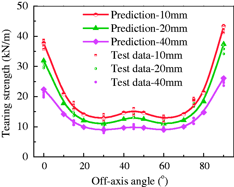
Overall, both the test data and predictions show typical W-shaped curves in Figure 15 for different slit lengths, which is not consistent with the results for bias tensile strengths obtained in previous researches [34,35,45]. There is a local peak at off-axis angle 45° in every curve, which is probably attributed to the yarn pullout and joint action of yarns of two directions in the vicinity of the slit tips. In fact, during a tearing test, most of the principal yarns in off-axial samples are damaged not so much in a tearing manner as in a pullout manner. This is due to the yarn–adhesive interface debonding that occurs gradually with producing a partially intact interface, which allows a broken yarn to be pulled out against the frictional stress along the debonding interface. Compared with the pure tensile failure of on-axial specimens, the mixed tensile and shear failure of off-axial specimens is more likely to give rise to the yarn pullout and yarn–adhesive interface debonding (see Figure 16), especially for the bias angle 45°. The yarn in the pullout process needs to absorb more energy than that in the rupture process [28,53,54] and yarn slippage at crossover points may significantly toughen tear damaged woven fabrics against tear propagation. Therefore, there would probably be a local peak at 45° angle in the curves of tearing strength-off-axis angle.
Typical tear propagation of off-axial specimens.
In addition, for the specimens of 45° angle, the yarns in two directions could take joint action to offer the resistance to tear propagation. As mentioned above, yarns in the samples could be divided into two kinds, namely, the principal yarns and secondary yarns. For the specimens of 30° or 60°, the principal yarns are mainly broken and the secondary yarns are pulled out or peeled off in the plateau region. Of the two kinds of yarns, the secondary ones could offer significantly less resistances to tear propagation than the principal ones. However, for the tests of 45° angle, all yarns in two directions are principle yarns, and they could give play to their joint action effect. During the tearing tests, not only the warp yarns but also the weft yarns were pulled out or broken by combined tension and shear. Owning to the effective joint action of the yarns in two directions, specimens of off-axis angle 45° could exert more load carrying capacity of the structural layer than some other angles, such as 30° and 60°, leading to a local strength peak in the curves shown by Figure 15.
This W-shaped relationship revealed by the formulas is useful in structural safety assessment, and the proposed formulas extend some existing criteria for tensile strengths [34,44,45] to predict the tearing strengths of laminated fabrics. Concerning the design practice and structural safety assessment, it might be recommendable in light of the great variety of the tearing strengths to conduct fabric structures analysis with a lower limit of the tearing strength. For the laminated fabrics with similar weaving structures, their lower limits of tearing strength can be obtained from the corresponding off-axial tests of 30° or 60°. If the variability is not so pronounced, then an average of both values might also be used for the lower limit value of material tearing strength.
Conclusions
This paper presents the research on fracture failure analysis and tearing strength criterion for laminated fabrics used in airship structures. The following conclusions can be drawn from the present study.
In the bias tensile tests, as the bias angle increases to 45°, shear deformation gradually becomes the dominant factor and the interaction of tension and shear stresses is increasingly obvious, and therefore, the failure mode of laminated fabrics changes from ‘yarn fracture’ to ‘mixed failure of tensile and shear’, and then to ‘yarn pullout’. According to the comparison between test data and predictions, Tsai-hill criterion is found to be a generally feasible theory to predict the bias tensile strengths for laminated fabrics.
For the model of tearing stress–displacement curves, it is found that a typical tearing stress–displacement curve could be defined as four characteristic regions: a co-deformation region, a yarn extension region, a plateau region, and a post peak region. Some differences exist between the on-axial and off-axial tearing behaviors, especially in the yarn extension region (or shear deformation region) and the plateau region of the tests. In the shear deformation region, for the off-axial samples, the shear deformation should be considered, and owing to the introduction of shearing stresses and the low shear stiffness of the woven fabrics, the slopes of the off-axial curves are obviously less than those of on-axial curves. In the plateau region, as the displacement increases, curves of both the on-axial and off-axial specimens experience fluctuations; however, there are more peaks in the off-axial curves, which should be attributed to the different phenomenon of yarn failure and durations of the plateau region. As there are obvious yarn pullout and yarn slippage, the plateau regions of the off-axial specimens could last much longer and experience more peaks than those of on-axial specimens whose yarns mainly break almost simultaneously.
For the tearing strength criterion for laminated fabrics, there is a W-shaped relationship between tearing strength and off-axis angle, with a local strength peak at 45° angle, which is not consistent with the results for bias tensile strengths. This local peak at off-axis angle 45° could be mainly attributed to the positive effects of yarn-pullout and joint action of the yarns in two directions. The W-shaped relationship could be regarded as a superposition of two parts: one is a U-shaped relationship from the Tsai-hill criterion, and another is an inverted V-shaped relationship from the off-axial constitutive relationship for shear modulus of orthotropic materials. Accordingly, a new tearing strength criterion is proposed and validated due to the high precision between the calculated and experimental results for the laminated fabric. Concerning the design practice and structural safety assessment, it might be recommendable in light of the great variation of the tearing strengths to conduct fabric structures analysis with a lower limit of tearing strength. For this kind of fabrics, the lower limit can be obtained from the off-axial tests of 30° or 60°. If the variability is not so pronounced, then an average of both values might also be used as the lower limit of material tearing strength.
Although this research is involved in one type of laminated fabric, the conclusions can also be applied to the similar laminated fabrics in the same woven technology to much extent. Based on this study, we can predict the stress reduction factor of tearing resistance and the critical slit length for a certain uniaxial stress state, and then we can further study the safety assessment of the airship structures.
Footnotes
Declaration of Conflicting Interests
The author(s) declared no potential conflicts of interest with respect to the research, authorship, and/or publication of this article.
Funding
The author(s) disclosed receipt of the following financial support for the research, authorship and/or publication of this article: This work was supported by the Fundamental Research Funds for the Central Universities (Grant No.30916011342), the National Natural Science Foundation of China (Grant No.51608270), the Fundamental Research Program of Jiangsu Province (Grant No.BK20150775), and the China Postdoctoral Science Foundation (Grant No.2016M601816).