
Abstract
The inkjet-printing technique was used to deposit a commercial silver nanoparticle ink in order to fabricate the electro-conductive layers directly on the different natural, synthetic, blend and mineral textile fabric surfaces with simultaneous sintering at 130℃ during printing process. This modification eliminated the necessity of sintering of silver prints in a box oven and significantly minimised ink spreading over the fabric. The silver nanoink used was characterised by means of ultraviolet-visible spectrometry, dynamic light scattering and transmission electron microscopy. The changes in surface resistance of the fabrics with the silver-deposited layers have been measured by means of the four-probe method. The morphology of the silver layers has been observed by optical microscopy and scanning electron microscopy. The conducting layers were also characterised chemically by means of energy dispersive spectroscopy. The changes in surface resistance of the silver inkjet-printed textiles were evaluated in the bending tests and after the rubbing, washing and dry-cleaning processes. The obtained results proved that the proposed shape-programmed inkjet-printing method was very simple, giving an excellent adhesion of the inkjet-printed silver layers to the substrates and ensuring a very low surface resistance. The studies have confirmed the usefulness of the ink applied for inkjet printing of silver electrodes and their good tolerance to bending, washing and dry-cleaning processes.
Keywords
Introduction
Textronics is a rapidly growing field that is a synergic combination of electronics, information technology and textiles. It allows for designing useful applications in which the textile product is used as a flexible substrate for the integrated active and/or passive components, or as a flexible substrate and a part of an electronic circuit. From the viewpoint of a textronics-based inkjet-printing technique, the key elements fabricated on textile substrates are the shape-programmed wires and electrodes, which allow one to fabricate electronic elements and sensors and to connect these elements with a main electronic processing circuit and power supply system by tracks printed on the textile substrate. Generally, the wires and electrodes should ensure a high conductivity – in an ideal case similar to the conductivity of silver or copper, which are usually used as a material for wires and electrodes in electronics. The most common and simple method used for fabrication of shape-programmed high electro-conductive layers on textile fabrics is screen printing. Some advantages of this method are high throughput, mature technology and simple tooling. The disadvantages that limit its use in fabrication of precision conductive layers on textile fabrics are low printing resolution and poor layer thickness control. This method was used for fabrication of silver-based transmission lines [1–3], electro-conductive tracks [3, 4], electrodes [5, 6] and antennas [7, 8] on different textile substrates. The most promising method to obtain highly conductive wires and electrodes on textile substrates consists of deposition of silver shape-programmed layers using silver-based inks and the inkjet-printing technique. Inkjet printing has advantages, such as low-cost, high-speed patterning and applicability to various substrates. Bidoki et al. [9] deposited silver patterns on cotton (CO) fabrics by using the reactive inkjet-printing technique. In experiments, aqueous solutions of silver nitrate and ascorbic acid were loaded into separate cartridges and printed sequentially on CO fabrics. The same method was used for printing silver patterns on paper and polyester (PET) fabric by Ghahremani et al. [10]. It was found that the conductivity of silver prints was dependent on concentration and repeating the printing sequence of each ink. Irurzun et al. [11] printed micro-sized lines on glass fibre fabrics by using a commercial silver nanoparticle ink and inkjet-printing technique. Prior to deposition, the substrate holder was heated to 70℃ in order to minimise ink spreading over the fabric. The deposited silver ink was sintered at 210℃ for 60 min. It was shown that the ink used spreads over hydrophilic glass fibre fabric, not allowing a continuous conductive line to be printed. This problem was solved by pre-treating the substrate with hexamethyl disilizane or amorphous teflon. Chauraya et al. [12] and Whittow et al. [13] reported a novel method of fabricating wearable microstrip patch antennas on PET/CO (65/35) fabric using inkjet printing and a commercial silver nanoparticle ink sintered at 150℃ for 10 min. Prior to ink deposition, the ultraviolet (UV) curable interface layer was screen printed on textile fabric. The efficiency of the fully fabric patch antennas was improved with the second layer of ink. The printed antenna did not significantly change its performance after bending around a 125-mm radius cylinder. Li et al. [14] reported a method of fabricating flexible capacitor for wearable applications, which has been all-inkjet printed on a standard PET/CO (65/35) fabric using a poly(4-vinylphenol) (PVP) dielectric material and a commercial silver nanoparticle ink sintered at 150℃ for 10 min. Prior to ink deposition, the UV curable interface layer was screen printed on textile fabric. Recently, the reactive inkjet-printing method using an aqueous silver ion-containing ink has been proposed [15]. In this research, the modified Tollens’ process for the preparation of a suitable and a low-cost water soluble silver ion-containing ink for the inkjet printing of textile substrates as a tool for the fabrication of different sensors, actuators and electronic devices for textronic applications was successfully applied. The observed changes in surface resistance confirmed that the reactive silver ink ensured very good inkjet printability of textile surfaces with simultaneous silver sintering at low temperature not exceeding 90℃.
As can be seen, it is possible to print silver-based layers on fabric substrates using the inkjet-printing technique but, due to the penetration of ink into the textile structure during printing, cutting an interface layer or many layers being printed is needed to achieve high layer conductivity. The use of interface layers causes the textile substrates being, in practice, totally insulated from the layer deposited, and the ink not to penetrate into the textile structure. The main disadvantage of this solution is that the interface layers lead to an increase in the stiffness of textile fabric. Practically, the silver layers printed on different textile substrates with using a silver nanoparticle ink were sintered at a temperature of about 150℃ for a few minutes in a box oven. In view point of textronic applications, the electrical conductivity of the silver inkjet-printed textiles should be stable after the bending, washing and dry-cleaning processes. In case of silver inkjet-printed textiles, the evaluation of changes in their electrical conductivity after these processes was not reported or in a very limited range.
Here, the inkjet-printing technique was used to deposit commercial silver nanoparticle ink in order to fabricate the electro-conductive layers directly on the different natural, synthetic, blend and mineral textile fabric surfaces with simultaneous sintering at 130℃ during printing process. This modification eliminated the necessity of sintering of silver prints in a box oven and significantly minimised ink spreading over the fabric. The silver nanoink used was characterised by means of ultraviolet-visible (UV-Vis) spectrometry, dynamic light scattering (DLS) and transmission electron microscopy (TEM). The changes in surface resistance of the fabrics with the silver-deposited layers have been measured by means of the four-probe method. The morphology of the silver layers was observed by optical microscopy and scanning electron microscopy (SEM). The conducting layers were also characterised chemically by means of energy dispersive spectroscopy (EDS). The changes in surface resistance of the silver inkjet-printed textiles were evaluated in bending tests, after the washing and dry-cleaning processes.
Materials and methods
Textile substrates
Characteristics of textile substrates used.

PAN: polyacrylonitrile; PET: polyester; CO: cotton; AR: aramid; WO: wool; PP: polypropylene.
Before printing, the textile substrates were ultrasonically cleaned with methanol and isopropanol for 20 min in each bath and then rinsed in an ultrasonic bath with deionised water and dried in an oven at the temperature of 40℃. In the final step, the residual organic contaminations were subsequently removed from textile substrates by 6 s UV radiation with an energy density of 0.5 W/cm2 using the stand presented in detail by Stempien et al. [16].
Conductive ink
Amepox MC NANO INK AX JP-60 n electrically conductive silver nanoink, a product of Amepox Microelectronics, Ltd., Poland, was used as received [17]. The average size and the concentration of the silver nanoparticle in this ink were around 50–60 nm and 20 wt%, respectively, as specified by the supplier. The viscosity and the surface tension of nanoink used were 5.5 cP and 35 mN/cm, respectively. The recommended short sintering temperature and duration time for the silver nanoink used are 130℃ and 20 min, respectively.
Deposition of silver layers on textiles
Electro-conductive layers on flat textile surfaces were printed using the inkjet-printing technique, in accordance with the scheme presented in Figure 1(a).
Silver deposition on textile surfaces using inkjet printing with simultaneous sintering: (a) scheme of deposition and (b) view of digital inkjet printer used.
For this purpose, a prototype of a digital inkjet printer shown in Figure 1(b) was used. It contained (Figure 1(b)): (1) nanodispensing hardware, represented by a one-nozzle valve-jet print head (ReaJet SK 1/080, Germany); (2) drive electronics for generating electrical signals to the print-heads; (3) an ink pump system and two ink reservoirs; (4) a two-axis (x-y) motion system for print head positioning with a step resolution of 35 µm, based on stepper motor linear drives; (5) a computer control system with software allowing the selection of a printing pattern and triggering of drops.
Before printing, the ink reservoir of the print-head was filled with silver-based ink. The print pattern was designed using a vector graphic editor and then converted to a line-art bitmap using raster image-processing software. The resolution of the line-art bitmap was 100 dpi and was the same as the resolution of the x-y print-head positioning system (100 steps per inch in the x and y axes). On the basis of the line-art bitmap, the drive-electronics system controlled the position of the print-heads and the release of the drops. The speed of the print-head during printing was 5 cm/s. The volume of the released drops was ∼30 nl. The electro-conductive silver layers were deposited line-by-line by inkjet-printing onto the surface of the fabrics placed on the hot-plate heated to a temperature of 130℃, ensuring simultaneous sintering of the silver-printed patterns. Due to the specific textile structure and its morphology, the inkjet-printing process was repeated several times to ensure the proper conductivity of the silver-printed patterns. The silver nanoink was deposited on the substrates specified in Table 1 at an ambient temperature in air. The amount of silver deposited on textile substrates was determined as the ratio of difference in weight of sample after and before printing and a silver layer surface.
Characterisation
UV-Vis spectrometry
The absorbance of the silver nanoink was characterised by the UV-Vis spectrophotometer. To adjust the absorption maximum between 0.2 and 1.2, the product was diluted with 96 vol.% ethanol properly. The UV-Vis spectrophotometer model JASCO V-530 (Japan) was used to record the silver plasmon band.
Dynamic light scattering
Because the silver nanoparticles’ size and the size distribution significantly influence the sintering process, which strongly affects the conductive properties of the Ag layers obtained, DLS was used to determine the size and the size distribution profiles of Ag-nanoparticles in Amepox ink. It was determined using the particle sizing system Nicomp 380, a product of Nicomp (Santa Barbara, CA, USA).
Transmission electron microscopy
TEM was used to determine the size and shape of Ag-nanoparticles in Amepox ink. It was determined using the Tecnai F20 X-Twin microscope, a product of FEI (USA).
Scanning electron microscopy
SEM with EDS was used to determine the silver layers’ morphology and to assess the distribution of silver on the textile surface. Energy-dispersive X-Ray spectroscopy extends the usefulness of SEM investigations by enabling elemental analysis within the regions at the level of a few cubic micrometres. The material was characterised by SEM using a field emission S-4700 microscope (Hitachi, Japan) equipped with an energy-dispersive spectrometer (Thermo-Noran, USA).
Surface resistance
For measuring the resistance of the printed samples, two- and four-point-probe methods were used. The surface resistance of the printed samples was estimated using the four-point method adapted to textiles. The four-point-probe setup used was presented in detail by Stempien et al. [18]. For each fabric, three independent silver prints were tested. The surface resistance was finally calculated as an average value of the measurements, and the standard deviation (SD) was determined. The two-point-probe method was used in order to evaluate the changes in electrical resistance of the silver prints in bending tests.
Tolerance to bending
The bending tests equipment is shown in Figure 2. It consisted of the rotating bending system with a stepper motor controlled by a computer system. The textile sample was mounted between the fixed and rotating clamps. The mounting edge of the rotating clamp acted as a bending line. It is situated in the rotation axis of the stepper motor, which allows for repetitive sharp bending of the sample by ±30°. The electrical resistance of the tested sample was measured in real time using the ohmmeter Picotest M3500A. On the basis of these measurements, the relative resistance R/R0 was determined, where R denotes a resistance measured during sample flexing, and R0 is the initial resistance of sample, respectively.
Principle of multi-cyclic bending of textile sample (on the left) and textile sample mounted in clamps during testing (on the right).
Rubbing fastness
The fastness of conductive properties of the silver electro-conductive prints to rubbing was estimated using the motorised AATCC crock meter CBT507, a product of CBT (Poland), according to scheme presented in Figure 3.
Fastness testing of silver conductive lines to rubbing: (a) scheme of the experimental set-up, where the rubbing finger was moved across and along the electro-conductive lines and (b) view of sample tested.
Prior to rubbing fastness testing, silver electro-conductive line (14 cm length and 3 mm width) was inkjet-printed on two separate samples of fabric and then two metal snaps (nickel finishing) were inserted at the two ends of each electro-conductive lines. A white CO lawn (5 cm × 5 cm) was mounted on the rubbing finger. The rubbing procedure consisted of 2000 cycles of the finger across the electro-conductive line for the first sample and along line for the second sample. A white CO lawn was replaced every 200 cycles. The electrical resistance of each tested electro-conductive line was measured in real time, after each rubbing cycle using the ohmmeter Picotest M3500A. On the basis of these measurements, the relative resistance R/R0 was determined, where R denotes a resistance measured during the rubbing process, and R0 is the initial resistance of sample.
Washing and dry-cleaning processes
The changes in surface resistance of the silver electro-conductive layers were estimated after washing and dry cleaning. Details of the washing and dry-cleaning procedures are specified as follows:
The washing process was carried out in the laboratory washing machine Linitest (Germany) for 30 min at 40℃. The liquor to sample weight ratio was 100:1. The samples with silver-deposited textiles were washed separately in distilled water containing 0.5% of non-ionic surfactant (MARLIPAL O13/70). The dry-cleaning process in tetrachloroethylene (PER) was carried out in the laboratory washing machine Linitest (Germany) for 30 min at ambient temperature. The liquor to sample weight ratio was 100:1. After dry cleaning, the samples were left for several hours at room temperature for the solvent to evaporate completely.
Results and discussion
UV-Vis silver nanoparticle ink characterisation
The distinctive colours of colloidal gold and silver are due to a phenomenon known as plasmon absorbance. Incident light creates oscillations in conduction electrons on the surface of nanoparticles, and electromagnetic radiation is absorbed. The wavelength of the plasmon absorption maximum in a given solvent can be used to indicate particle size. In general, as the particles become larger, the plasmon peak shifts to longer wavelengths and broadens [19]. The spectrum of the pale yellow Amepox nano-silver ink in 96 vol.% ethanol is shown in Figure 4. The UV-Vis spectrum recorded exhibits a plasmon absorption band at ∼427 nm that is characteristic of silver nanoparticles.
UV-Vis spectrum of the silver nanoink showing the surface plasmon band of silver nanoparticles.
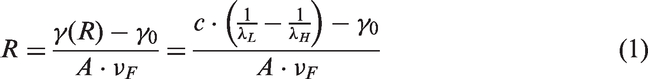
On the basis of Mie theory and its expanded versions [20–22], the Ag particle size R can be derived from the analysis of UV-Vis spectrum from equation (1)
Characterisation of silver nanoparticles in Amepox ink by DLS
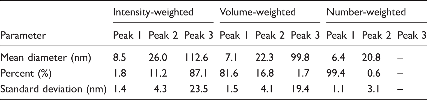
In Figure 5, the Nicomp distribution analysis of the intensity-, volume- and number-weighted data collected for the sample containing nano-Ag particles dispersed in ethyl alcohol is presented. As can be seen, the Nicomp distribution analysis of the size profiles revealed that there are no distinct changes in the intensity-, volume- and number-weighted profiles of the nano-Ag particles investigated. Detailed analysis of the all data obtained and shown in Table 2 confirms that the mean diameter size of the nano-Ag particles in Amepox ink is approximately 6–8 nm, taking into account the number- and volume-weighted intensities and their respective SDs. It should be noted that the average size of silver nanoparticles in this ink, specified by a supplier, was around 50–60 nm. The difference in our data and those delivered by supplier results from the application of the Malvern instrument by the supplier, giving the Gaussian distribution profile, which ensures the general information is in the broad range only. The special Nicomp distribution program is more informative and allows for obtaining the more detailed fraction distribution of the sample studied.
Nicomp distribution analysis of the intensity-, volume- and number-weighted data for the sample Amepox ink dispersed in ethanol. Nicomp distribution analysis of the intensity-, volume- and number-weighted data collected for the nano-Ag particles in Amepox ink dispersed in ethanol.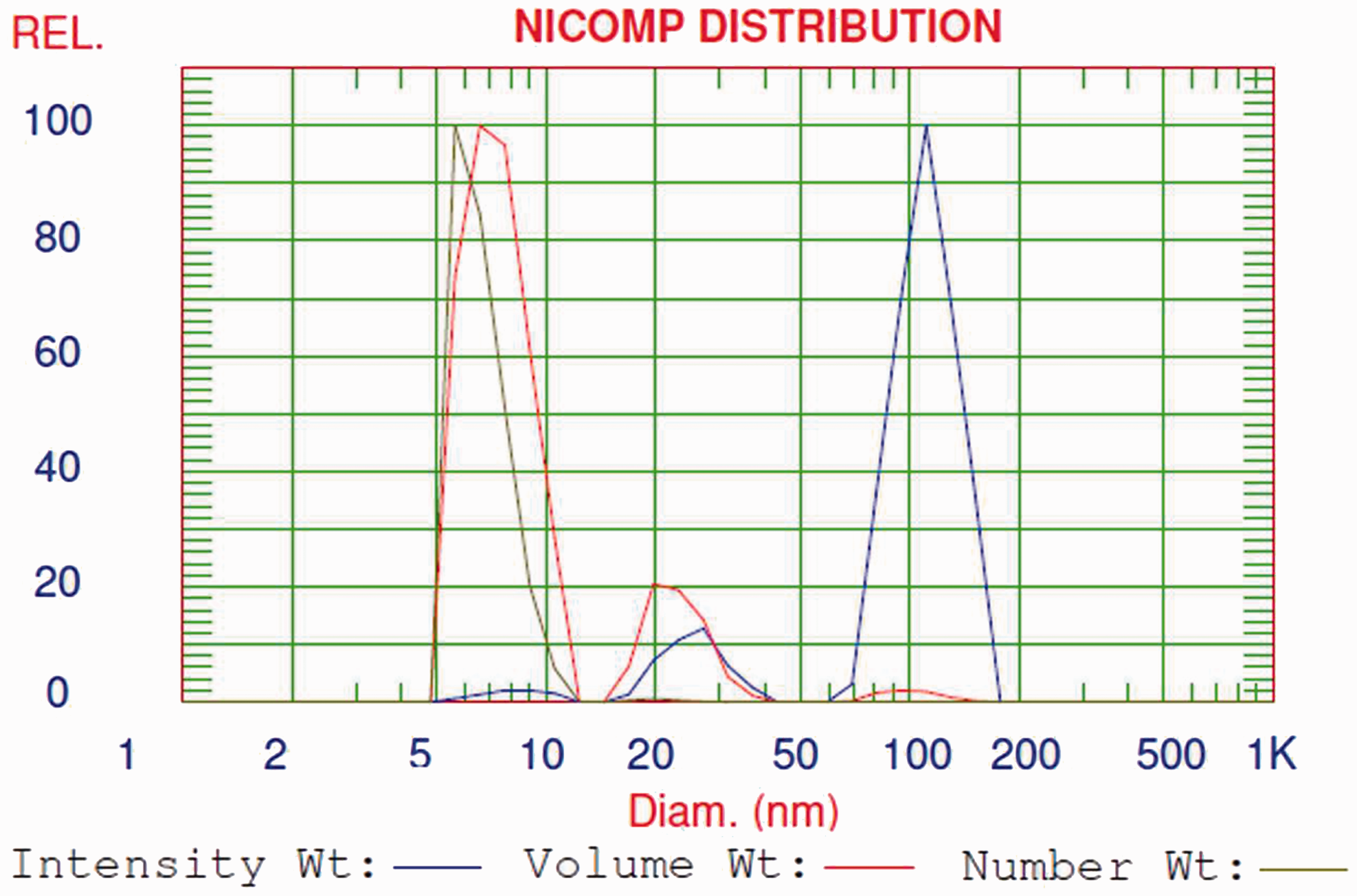
To confirm that the diameter size of the nano-Ag particles in Amepox ink was in the range of 6–8 nm, TEM was used. The TEM images of silver nanoparticles for the sample Amepox ink dispersed in ethanol are presented in Figure 6. As it can be seen, the silver nanoparticles are spherical in shape and have smooth surface and similar sizes. The diameter of silver nanoparticles was found to be approximately 8–9 nm as it was also determined by the use of DLS and UV-Vis spectrometry.
TEM images of silver nanoparticles for the sample Amepox ink dispersed in ethanol: (a) image of several silver nanoparticles and (b) image of a single silver nanoparticle.
Optical microscope images of silver-deposited textiles
Figure 7 shows photographs (taken with an Olympus stereomicroscope SZX-10) of a representative set of samples of silver printed (eight passes) and sintered on different textile substrates. Looking from the left side of each figure, the raw material, silver layer printed on the pre-treated fabric and view of printed surface magnified by 10× can be seen.
Optical microscope images of Ag/fabric composites: (a) Ag/PAN, (b) Ag/PET, (c) Ag/Basalt, (d) Ag/CO, (e) Ag/CO/PET, (f) Ag/Aramid, (g) Ag/WO and (h) Ag/PP.
The images show that the silver prints on different textile substrates have good uniform dark silvery hues, which are characteristic of silver formation. It should be noted that for all the textile substrates, the quite sharp edges of the prints were retained and the lack of silver spread and of the coffee-ring effect was observed. This is important from the viewpoint of fabrication of the precision electro-conductive wires and electrodes on textile surfaces by the inkjet-printing technique for textronic applications. It allows for fabrication on textile surfaces, the narrow and close-placed wires and electrodes having different shapes on regions of a textronic device. The magnified-printed surfaces show a quite good uniform distribution of silver on the textile surfaces after sintering.
Surface morphology of silver layers
The SEM images of the Ag/textile composites were taken at magnifications of 1000×, 2500× and 5000× for the samples prepared from the nanosilver ink with eight inkjet-printed layers and simultaneously sintered at temperature of 130℃ on the hot plate. The presence of Ag can be clearly seen on all the inkjet-printed textile fabrics. It is evident from Figure 8 that all the surface areas of the fabrics are fully coated with Ag and have a non-uniform and non-smooth surface. Some cracks on the silver surface are also observed. This phenomenon can be explained by the sudden evaporation of ink drops from the textile substrate during printing process due to a high temperature of hot plate. The overall SEM study proved that the fabrics studied were successfully covered with Ag, and that the Ag nanoink penetration into the structure of the fabric during inkjet printing.
SEM of Ag/textile composites: (a) Ag/PAN, (b) Ag/PET, (c) Ag/CO/PET, (d) Ag/CO, at magnifications of 1000×, 2500×, 5000×.
The Ag/polyacrylonitrile (PAN) composite sample, as an example, was also subjected to EDS survey analysis to identify the elements present on the fabric surface and their distribution. EDS studies revealed that the Ag print on PAN fabric contains mainly silver. Comparison of the SEM image, taken at a magnification of 1000×, with the EDS investigations of the analysed sample shows that, on the surface of the PAN fabric, a thick layer of Ag is clearly visible. Bright spots appearing on the X-ray maps (Figure 9) depict places with higher concentrations of the studied element, and also confirm the presence of a non-uniform Ag structure.
SEM micrograph (1000×) and EDS measurements of the Ag/PAN composite.
Surface resistance
Changes in the surface resistance of silver-finished textiles (Ω/sq.) including ±SD vs. number of layers deposited.

PAN: polyacrylonitrile; PET: polyester; CO: cotton; AR: aramid; WO: wool; PP: polypropylene.
Also, the inkjet printing of textile substrates revealed that all the natural, synthetic, blend and basalt fabrics can be efficiently printed with the silver ink. The inkjet-printing process carried out on textile substrates made of natural, synthetic fibres, e.g. CO and CO/PET mixtures, has shown that the silver layer prints achieved were characterised by sharp edges and without coffee-ring effects, ensuring the proper conductivity needed for textronics applications was achieved.
Tolerance to bending
Figure 10 shows the changes in the relative resistance of the silver-finished textiles (eight inkjet-printed silver layers) after 50,000 bending cycles. The initial resistances of PAN, CO, PET and CO/PET silver-printed textiles were 0.42 Ω, 0.44 Ω, 0.28 Ω and 0.52 Ω, respectively. After the 50,000 bending cycles, the final resistances of samples studied were ∼1.3 Ω, 2.6 Ω, 1.5 Ω and 2.5 Ω, respectively. Generally, the relative resistance for the silver-finished textiles increases with the number of bending cycles because of the fabric structure and silver layer damage processes. Wang et al. [23] reported that crack initiation in the Cu thin film deposited on a flexible substrate can be detected by the electrical resistance change. Based on this finding, for our tested silver-printed textiles, two distinct regions could be clearly seen in the relative resistance versus number of bending cycles (Figure 10). In the first region, no damage in the fabric exists, and the relative resistance increased slightly with the number of bending cycles due to the change in the fabric structure along the bending line caused by elongation of the yarns and the decrease in fabric cross-section. For the tested fabrics, the relative resistance in this region increased by 5%–10%. As the number of bending cycles increased, damage in the fabric structure was induced and the formation of cracks in silver layer caused the significant increase in the relative resistance. The values of fatigue lifetime for the tested PAN, CO, PET and CO/PET fabrics were ∼800, 200, 50 and 120 cycles, respectively.
Changes in the relative resistance of silver-finished textiles after multi-cycle bending.
Rubbing fastness
The four textile substrates (PAN, CO, PET and CO/PET) with silver electro-conductive lines were subjected to the rubbing fastness procedure. Figure 11 shows the changes in the relative resistance of the silver electro-conductive lines printed on selected textile substrates after multi-cycle rubbing, while the rubbing finger was moved across (a) and along (b) the electro-conductive lines.
Changes in the relative resistance of silver electro-conductive lines printed on textile substrates after multi-cycle rubbing, while the rubbing finger was moved: (a) across the electro-conductive lines and (b) along the electro-conductive lines.
Generally for the first 1000 rubbing cycles, the relative resistance of the silver electro-conductive lines increases gradually with an increase in the number of rubbing cycles for all textile substrates. The increase in resistance was higher when the rubbing finger was moved along the electro-conductive lines. It was caused by the progressive damage of the silver lines during rubbing on the longer distance. In Figure 12, the view of silver-printed PAN fabrics after 2000 rubbing cycles across and along the electro-conductive lines are presented.
View of silver-printed PAN fabrics after 2000 rubbing cycles: (a) rubbing across the electro-conductive line and (b) rubbing along the electro-conductive lines.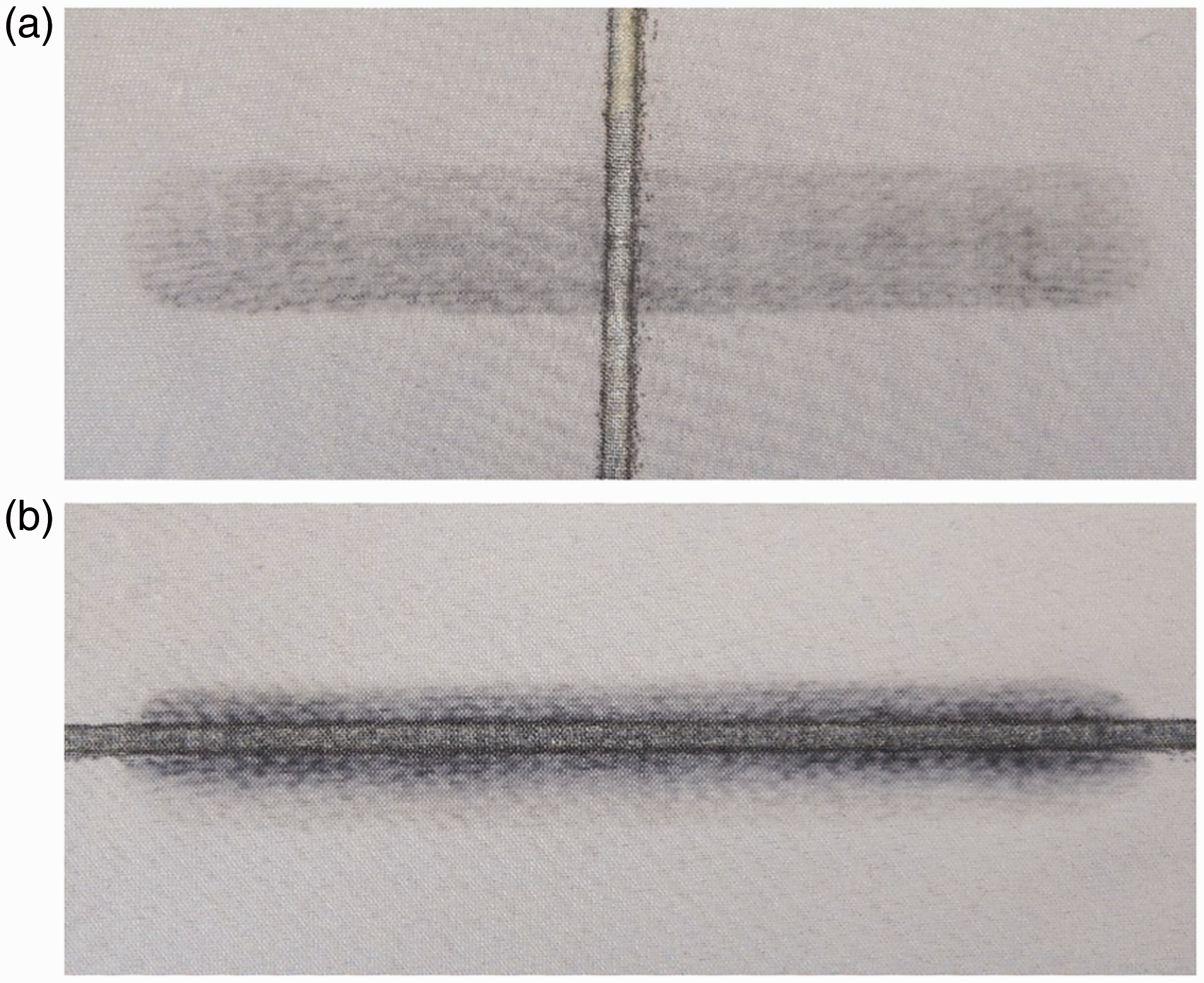
As it can be seen in Figure 12, reduction in conductivity of silver lines was caused by separation of some amounts of silver particles from the fabric surface. This process was much more meaningful for rubbing along the silver line. In the case of CO/PET fabric, the relative resistance increased suddenly after 1200–1500 rubbing cycles. It can be explained by the limited adhesion of silver layer to CO/PET fabric as well as relevant disintegration of fabric structure due to rubbing. Taking into account, the overall results of the measurements of rubbing fastness, it can be concluded that the rubbing fastness of the silver-printed fabrics was relatively good to meet the commercial requirements for a wide range of applications in textronic systems.
Washing and dry-cleaning processes
Changes in the surface resistance of silver-finished textiles (Ω/sq.) including ± SD after washing and dry cleaning.

PAN: polyacrylonitrile; PET: polyester; CO: cotton.
The greatest differences are observed in the washing process, especially for PAN fabric. In practice, the washing and the dry-cleaning processes only slightly affect the change in the surface resistance of the inkjet-deposited silver on textile substrates. The observed changes in the surface resistance caused by the dry-cleaning process are comparable to those observed in the washing process and can be neglected. The data obtained proved that all the textile substrates studied show a very good resistance to the washing and dry-cleaning treatment, and that all textile samples still retain a very good electro-conductivity, which is important from the point of view of their further application in textronics. However, it should be noted that the CO fabric has shown the highest resistance to the washing and dry-cleaning processes.
This is probably caused by the specific structure of the CO cellulose and its change during the inkjet printing of an alcohol- and ethylene glycol-containing nanosilver ink. It is known that CO fibres in their anatomy have the numerous micropores, microcapillary cracks and voids of very different sizes and shapes, significantly changing with various moisture ratios [24]. Also, using differential scanning calorimetry based on the Gibbs–Thomson effect, it was found that larger pores (>100 nm) appear when the moisture ratio of CO fibres increases, and a majority of pores of around 50 nm radius is observed [25]. Abu-Rous et al. [26] studied the anatomy structure of CO fibre using the TEM technique and demonstrated that CO fibre had a porous structure with a pore size in the nanometer scale. This characteristic feature of the structure of CO fibre was used previously to create silver nanoparticles in situ on and in the CO fibres by the reactive inkjet- and screen-printing methods, aimed at long-lasting antibacterial finishing [27, 28]. Earlier, and on this basis, the mechanism of anionic surfactants adsorption on CO was explained [29]. Hence, one can imagine that the nanosilver-containing ink of a low surface tension used in this work may easily penetrate the pores and voids in the supramolecular structure of CO fibres, thus causing a kind of anchor for the subsequent silver inkjet-printed layers.
Conclusions
The controlled deposition of silver electro-conductive layers in well-defined patterns on different textile fabrics by inkjet printing from a commercial silver nanoink has been demonstrated. It was found with UV-Vis spectrometry and DLS that the diameter size of the nano-Ag particles in nanoink was around 7 nm; however, according to the supplier specification, it should have 50–60 nm diameter. The observed changes in surface resistance confirmed that the silver ink used ensured very good inkjet printability of textile surfaces with simultaneous silver sintering at quite low temperatures not exceeding 130℃. SEM–EDS analysis revealed that silver can be found on different textiles after silver inkjet printing and sintering. To achieve proper conductivity of the textile patterns, several silver-printed layers are needed. The study confirmed the usefulness of the ink applied in printing silver patterns on textiles and their good tolerance to bending, rubbing and the washing and dry-cleaning processes.
Footnotes
Declaration of Conflicting Interests
The author(s) declared no potential conflicts of interest with respect to the research, authorship, and/or publication of this article.
Funding
The author(s) disclosed receipt of the following financial support for the research, authorship, and/or publication of this article: This research was supported by the Polish National Centre for Research and Development (NCBiR) Grant PBS3/A9/34/2015 in the framework of the Applied Research Programme.