
Abstract
Bi-functional nanofibrous membrane composed of polyurethane in one face and poly(2-acryloylamido-2-methylpropanesulfonic acid)-graphene oxide (PAMPS-GO) in another face has been fabricated using two opposite-nozzle electrospinning set-up. The effect of graphene oxide addition on morphology of PAMPS nanofibers and performance of membrane were investigated. Besides structure of graphene oxide layers, electrospun nanofibers were studied using TEM, X-ray, FTIR, and FE-SEM methods. To evaluate the nanofibrous membrane performance, their tensile strength, water vapor permeability, and contact angle were measured. An average diameter of 500 nm and 83 nm were obtained for PU and PAMPS nanofibers, respectively, through the optimized electrospinning process. Results show that PAMPS nanofiber diameters together with pore sizes of its mat decrease by increasing the graphene oxide content. Also, the dimensional stability of electrospun fibers against water vapor was strengthened in the presence of graphene oxide nanosheets. An improvement in tensile strength of PAMPS nanofibers was observed by the addition of graphene oxide up to 0.2 wt.%, while more addition caused a negative change. Studying water vapor permeability of PAMPS nanofibers showed that increasing the graphene oxide content, the water vapor permeability increases. However, it decreases by increasing the surface density of nanofibers. From a hydrophobic–hydrophilic perspective, an excellent dual-mode behavior on two opposite faces was observed that is already proper for water proof-breathable protective clothing and wound dressing applications.
Keywords
Introduction
Waterproof-breathable membrane is an important subject in protective clothing (PC) sector. Resisting against liquid and allowing water vapor to permeate through the clothing system are two main features providing protection and comfort for human body [1–4]. In order to provide protection and comfort simultaneously in PC, a protective medium with antithetical modes is needed. In the case of the water proof-breathable PCs, membranes with hydrophobic nature at the outer face (for protection against rain and wind) and a hydrophilic nature at the inner face (for moisture managing of skin sweat and evaporating cooling) are needed [5,6]. Generally, the trend toward more efficient performance for clothing systems has been aided by development of the so-called breathable membrane, based on microporous hydrophobic polymers such as polytetrafluoroethylene (PTFE) and polyurethane (PU). These materials retain excellent waterproof and windproof properties, based on their hydrophobic nature and transmit water vapor across the membrane pores.
Recently, breathable membranes have also been produced with electrospun polymers which offer a great potential for protective clothing [1,2,5,6]. Porous membrane-based on PU electrospun nanofibrous membranes (ENMs) by Gibson et al. [2], layered fabric systems based on PU electrospun nanofibers by Lee and Obendorf [5], wind proof electrospun nanofibrous PU membranes by Gorji et al. [1], waterproof electrospun layer composed of PU and Nylon 6,6 hybrid nanofiber by Amini et al. [6], superamphiphobic breathable membranes utilizing SiO2 nanoparticles by Wang et al. [7], hydrophobic-breathable membranes with water/windproof performance by Yang et al. [8], and tunable porous structure fibrous membranes by Li et al. [9] are some of the successful researches in this field. To the best of our knowledge, all of previous researches have focused on electrospinning of hydrophobic materials which are adapted well to waterproof property of clothing system. But the most important requirements for clothing in humid condition are fast water vapor permeation and comfort. Incorporating a hydrophilic electrospun layer gives an additional function to the clothing systems which can be easily developed by using a two opposite-nozzle electrospinning set-up.
Bi-functional water proof-breathable membranes with hydrophobic nature at the outer face and a hydrophilic nature at the inner face are aimed at this work, using two-nozzle electrospinning set-up. Here, polyurethane (PU) and poly(2-acryloylamido-2-methylpropanesulfonic acid) (PAMPS) were used as the polymers with hydrophobic and hydrophilic natures, respectively. PAMPS is a water-soluble and ionic polymer with high degree of hydrophilicity which has been paid great attention as superabsorbent matter for PC [10,11]. The sulfonate groups of PAMPS are responsible for high hydrophilicity and anionic character of the polymer. Hydrophilic nature of PAMPS leads to a final structure with enhanced water absorption and transport characteristics [12,13]. Despite of good water absorption and transport capacity of PAMPS nanofiber membranes, the mechanical and dimensional stability of these structures is not satisfying to apply in protective clothing. Graphene oxide (GO) was synthesized from graphite and used as PAMPS filler. GO is used for increasing mechanical and transport properties of PAMPS nanofibrous structures. It has been reported that GO sheets due to plenty of hydrophilic groups on their surface, could increase the water diffusion rate in nanocomposites [14]. A significant enhancement of mechanical properties also has been reported by researchers [15–17]. Tian et al. [18] prepared regenerated cellulose/graphene fibers and found that 50% increment of tensile strength was achieved by adding 0.2 wt% graphene oxide. Their results also showed that the composite fiber could remarkable absorb more heat from surrounding conditions. Xu and Gao [19] reported an increase of 2.1 and 2.4 folds for the tensile strength and Young’s modulus by adding 0.1 wt% graphene to melt-spun nylon-6 fiber. Milani et al. [20] proved that graphene nanosheets not only increased Young’s modulus but also enhanced the dimensional stability of polypropylene–graphene nanocomposite.
In this study, P(AMPS-GO) with a low GO content was synthesized by radical polymerization of AMPS and GO in DMF solvent. PU and P(AMPS-GO) nanofibers were electrospun individually by single electrospinning to detect the optimum production conditions. Then, using electrospinning set-up with two opposite nozzles, three-layer membranes composed of PU nanofibers on one side, bimodal fiber diameters PU/P(AMPS-GO) in the middle, and P(AMPS-GO) on the other side were fabricated. The effect of GO content on morphology, mechanical properties, and water vapor permeability (WVP) of obtained ENMs were measured.
Experimental
Materials
All chemicals were purchased from analytical sources and were used as received otherwise noted. Tetrahydrophoran (THF), N,N-dimethylformamide (DMF), sodium nitrate (NaNO3), concentrated sulfuric acid (H2SO4), hydrochloric acid (HCL) and potassium permanganate (KMnO4) were purchased from Merck (Germany). 2-Acrylamido-2-methyl-1-propanesulfonic acid (AMPS, monomer, ≥99%) and graphite powder were obtained from Daejong Co. (South Korea). Hydrogen peroxide (H2O2) and 2,2-azobisisobutyronitrile (AIBN) were purchased from Sigma-Aldrich (St. Louis, MO, USA). PU also was obtained from Byer (Leverkusen, Germany).
GO and P(AMPS-GO) synthesis
GO nanosheets were synthesized according to the Hummer method [21]. In brief, graphite powder (2 g) and NaNO3 (1 g) were dissolved into H2SO4 (46 mL) and were stirred in a three-neck flask placed in an ice bath for 2 h. Then, KMnO4 (6 g) was added gradually under stirring and the temperature of the mixture was kept below 20℃. The solution was heated to 35℃ and kept for 2 h. After that, distilled water (92 mL) was slowly poured into the suspension and the temperature was controlled to be below 100℃. After 15 min, adequate amount of distilled water and 5 mL of 30% H2O2 solution were added to wash the residual KMnO4. Finally, the mixture was filtered and washed with 5% HCl aqueous solution and water until the pH value of the upper layer suspension approached to 7. Furthermore, sonication with a cylindrical tip was used for exfoliation of graphite oxide to GO.
P(AMPS-GO) was synthesized according to the procedure reported previously [22]. In brief, AMPS (17.031 g) and DMF (40.623 g) and desired amount of GO were placed into a three-necked round-bottomed flask (100 mL). Then, 0.190 g of initiator (AIBN) was added under dry nitrogen atmosphere and the mixture was stirred for 10 h at 80℃ in water bath to form 30 w/v% PAMPS solution with different GO content.
Electrospinning
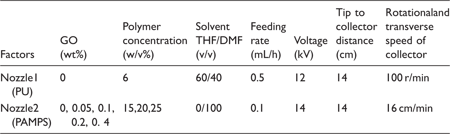
PU solutions were prepared by dissolving 6 w/v% of PU pellets in THF/DMF(60/40 v/v) solvent for all tests. Composite ENMs were fabricated using two-nozzle electrospinning set-up. Accordingly, PU nanofibers were electrospun on an aluminum foil first, and then PU/PAMPS nanofibers were provided by the simultaneous electrospinning of different precursor solution from two syringes and finally the procedure was followed by electrospinning of PAMPS nanofibers. Although the PAMPS concentration and GO loading were altered in different tests, in any given test, a unique solution was used for both middle and inner layers. The scheme of electrospinning process is presented in Figure 1.
Scheme of synthesize of P(AMPS-GO), electrospinning set-up and obtained three-layer membrane.
Electrospinning conditions for two opposite nozzles set-up.
Characterization
Transmission electron microscopy (TEM, Zeiss – EM10C) was employed to study the morphology of prepared GO, with an accelerating voltage of 80 kV. In order to determine the phase structure of the graphite and GO products, the X-ray diffraction (XRD) patterns were recorded using an INEL (Equinox3000, France) X-ray diffractometer with a Cu–Kα radiation (λ = 1.5418 Å) source.
The morphology of the electrospun nanofibers were characterized using scanning electron microscopy (FE-SEM, Mira3-XMU; SEM, Seron Technology, AIS2100; SEM, KYKY, EM3200). SEM images were processed using Image J software (National Institute of Health, Bethesda, MD, USA), reading 100 pixels in instance, leading to average fiber diameter and its distribution. Also, average pore diameter was measured by image processing method. After obtaining the average and standard deviation of light intensity of samples, SEM images were converted to gray scale with 256 levels. Three different thresholds were defined based on mean (μ) and standard deviation (σ) as below:
Threshold 1: (µ+σ)/255
Threshold 2: µ/255
Threshold 3: (µ-σ)/255.
Based on these thresholds, each sample’s image changed to three different layers [23]. The pore diameters were measured in 50 points of each layer using the Image J software followed by pore diameter average calculation.
The tensile strength of the nanofibrous membranes was determined using Instron 5560 instrument at room temperature at a crosshead speed of 50 mm/min. According to ASTM D-638, five dumbbell-shaped specimens were tested from each sample and the average values were reported.
Water vapor permeability (WVP) of samples was measured using a tester M261 (Atlas, England) according to ASTM E 96-00. The wettability of ENMs surfaces was studied by homemade contact angle test apparatus. For measurement, the water was dropped from a micro syringe needle on the membrane surface. Drop picture was captured using a digital microscope camera and then contact angles were calculated through analyzing the drop shape. An average of 20 measurements was reported.
Results and discussion
Characterization of GO and P(AMPS-GO)
Figure 2 shows TEM images of GO synthesized in this study with different magnifications. According to these pictures, the GO nanosheets are almost transparent, indicating that the graphite oxide is significantly exfoliated. Besides, as shown in Figure 3, the XRD patterns of the samples confirm the conversion of graphite oxide into graphene oxide. In Figure 3, the XRD patterns of graphite, GO, and P(AMPS-GO) before and after electrospinning are provided. The (002) diffraction peak of graphite appears at 2θ = 26°, corresponding to a lattice spacing of 0.3 nm. From this figure, it can be seen that after oxidization, the (002) diffraction peak of GO at 2θ = 26° intensely declines, and a new small peak at 2θ = 8° indicating an interlayer spacing of 1.0 nm appears. Increase of interlayer spacing in GO multilayers (1.0 nm) compared to that of graphite (0.3 nm) indicates that oxygenated groups cause the graphite oxide sheets to stack more loosely. On the other hand, the increased background noise from X-ray diffraction profile is related to weak signals which are assigned for graphite oxide (GtO) multilayers with different interlayer spacing. A weak and broad peak is replaced with the sharp peak of GO around 2θ = 8° in the case of P(AMPS-GO) before electrospinning. This result certifies that the polymer chains act as intercalating agent, penetrate between the GtO nanogalleries, and help neighbor sheets with more exfoliation. It seems that electrospinning process can assist the exfoliation of GO layers. Besides, if a possible polymer grafting on graphene oxide surface can be imagined so the average delamination of nanolayers of GO is forced during the electrospinning [24]. During electrospinning process, a considerable tension is inserted on the polymer chains which moves from Taylor cone toward collector; this tension consequently transfers to the GO lattice due to the grafted polymer chains.
TEM images of GO with different magnifications. XRD patterns of graphite, GO and P(AMPS-GO) (with 0.4 wt% GO) before and after electrospinning.

Morphology of nanofibrous sructures
Figure 4 shows the SEM images and diameter distribution of electrospun nanofibers (outer face) from a 6 w/v% PU solution, simultaneous electrospun nanofibers from a 6 w/v% PU solution, and 25 w/v% PAMPS nanofibers (middle layers) and nanofibers from a 25 w/v% PAMPS solution (inner face).
The morphology, average diameter and the standard deviation of nanofibers: (a) PU (Mean: 519 nm; SD:79); (b) PU/PAMPS (Mean: 528 nm, 87 nm; SD: 137, 20); (c) PAMPS (Mean: 126 nm; SD: 37).
As Figure 4 shows, successfully prepared bead-free fine uniform nanofibers were achieved for both PAMPS and PU. Interestingly, for PAMPS solution, fine electrospun nanofibers with average diameter of 126 nm were obtained while a larger diameter of 519 nm which is about four times that of average diameter was achieved for PU solution. This difference can be explained in part by this fact that PAMPS is an ionic polymer with high degree of sulfonic acid whose electrical charge causes to increase charge density in electrospinning solution. As the charges of electrospinning jet increased, higher elongation forces were imposed to the jet under the electrical field, resulting in thinner fiber diameters [25]. Figure 4(b) presents bimodal fiber distribution successfully fabricated by simultaneous electrospinning of PU and PAMPS by two opposite nozzles. According to the images, the mean diameter of PU nanofibers remains almost constant, but the mean diameter of PAMPS nanofibers dropped from 125 nm to 87 nm, when electrospinning was performed from one- to two-nozzle, respectively, at the same processing conditions. This reduction in mean diameter of PAMPS nanofibers can be related to the change of electrical field which is probably affected by other working nozzle.
Figure 5 shows the SEM images and corresponding nanofiber diameters distribution of electrospun mats for different concentrations of PAMPS. It is apparent from these images that the average diameter of nanofibers increased constantly from 75 nm to 93 nm, when the concentration increased from 15 to 30 w/v%. Increased viscoelastic force due to higher polymer concentrations can resist against the electrostatic force which leads to larger diameter in electrospun nanofibers.
The morphology of PAMPS nanofibers (left) and corresponding fiber diameter distribution (right) at concentrations of (a) 15 w/v%; (b) 20 w/v%; (c) 25 w/v% and (d) 30 w/v%.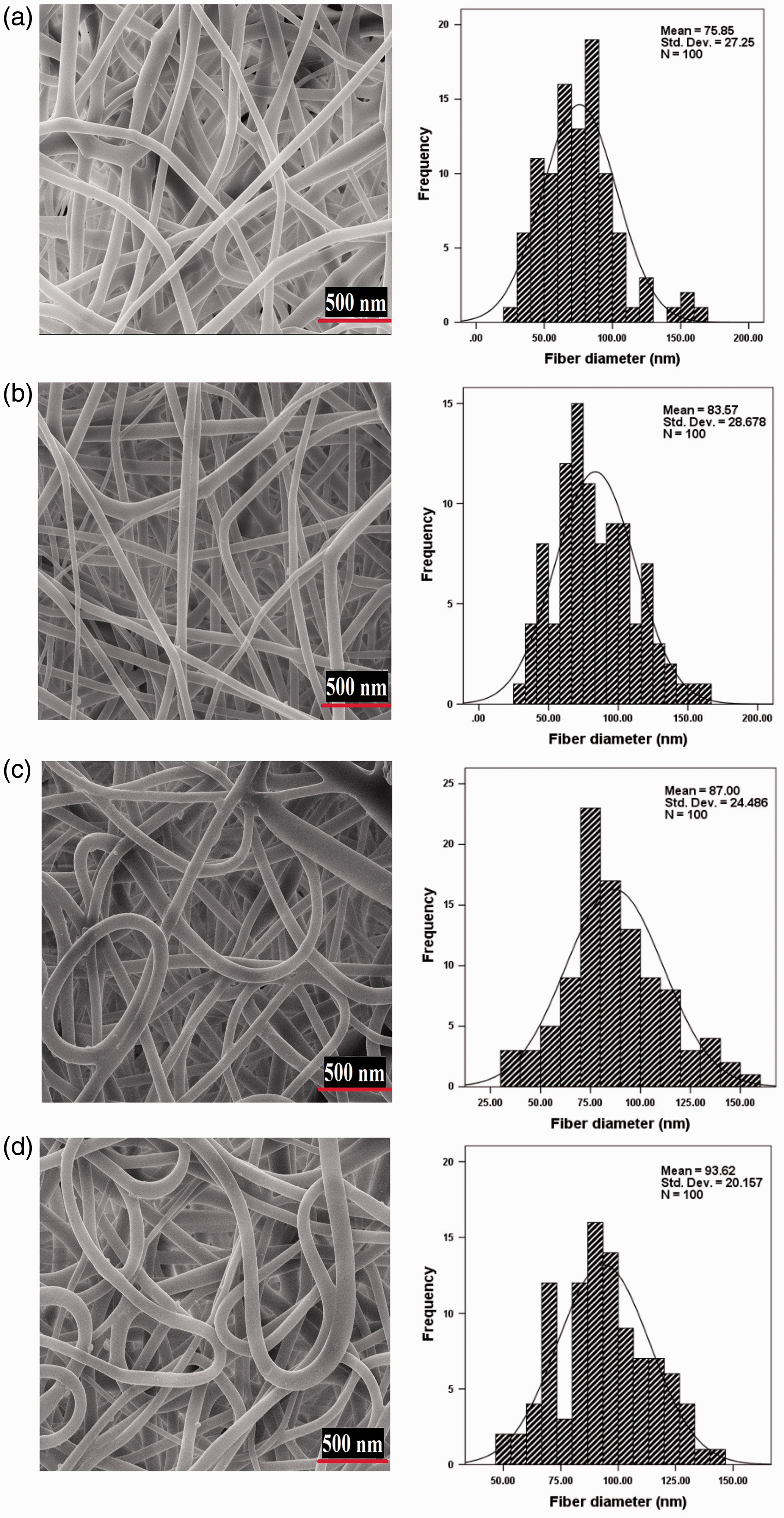
Figure 6 shows the morphology of electrospun PAMPS and P(AMPS-GO) nanofibers as well as nanofiber diameter distribution at high magnifications. The results attained for 30 w/v% PAMPS solution indicate a decrease in diameters of electrospun PAMPS nanofibers from 90 nm to 70 nm by increasing the GO content in range of 0.05–0.4 wt.%. The reduction in average diameter can be described by solution conductivity. GO content due to sp2 and sp3 carbon domains and accelerating electron transportation, increases the conductivity of electrospinning solution [26,27]. The increase in the solution conductivity led to more stretching of polymer solution under high electrical field due to the repulsion of the charges present on its surface and producing nanofibers with fewer diameters [28].
FE-SEM images of P(AMPS-GO) electrospun membranes (left) and corresponding fiber diameter distribution (right) from solution 30 w/v% PAMPS in the presence of (a), 0.05%, (b) 0.1% (c) 0.2% and 0.4% GO.
It is worth noticing that in samples in which GO was mixed with AMPS monomer for in-situ polymerization, exfoliation of GO nanosheets and also uniformity of resultant nanofibers are improved in comparison with the case in which GO was added to polymer solution, i.e. after polymerization. Figure 7 shows PAMPS/GO nanofibers electrospun from solution prepared by dissolving PAMPS and GO at 30 w/v% in DMF. As seen in Figure 7, semi-exfoliated graphite oxide was observed in the PAMPS/GO structures; in this case, GO was added into the PAMPS solution and dispersed by solution blending, resulting in formation structures with nanobeads. As a result, in-situ polymerization of AMPS/GtO causes more AMPS monomer diffusion between GO layers, widens them and supports more exfoliation which results in enhanced dispersion of GO in polymer network. The better exfoliation and dispersion of GO nanosheets led to more uniform nanofibers formation during the electrospinning process.
SEM image of nanobead(left) and semi-exfoliated GO (right) from solution of 30 w/v% PAMPS in blend with 0.2 wt% GO.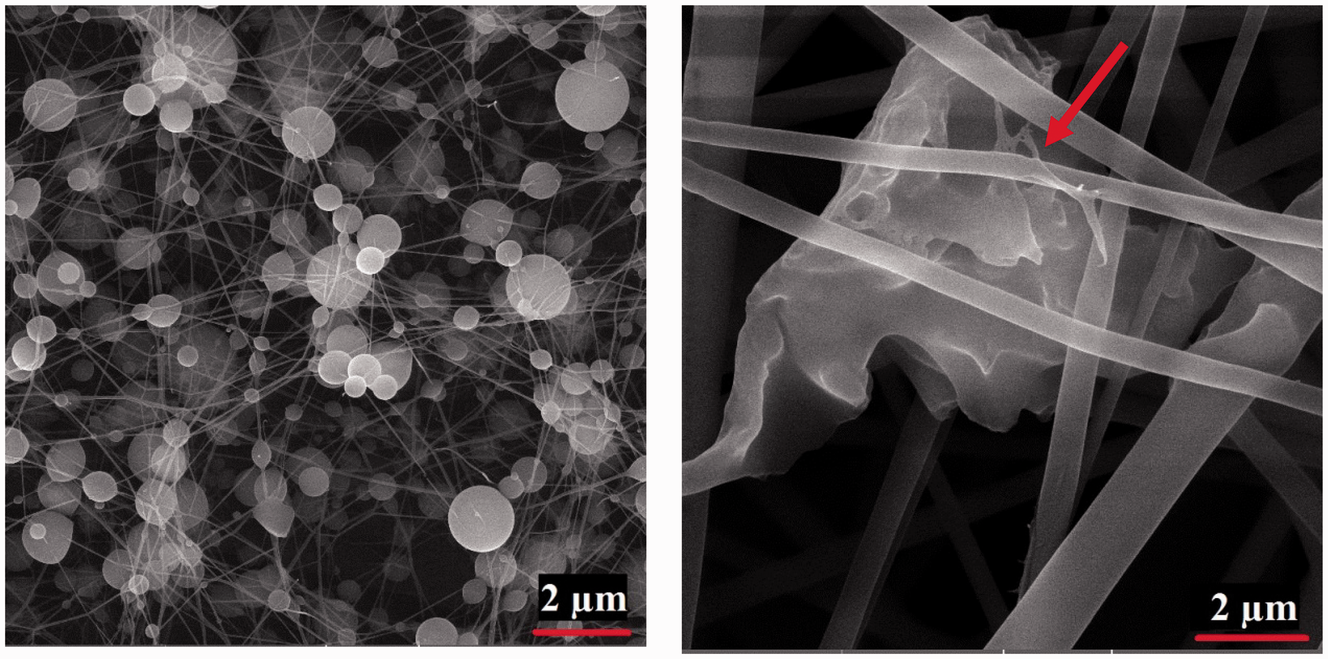
Pore diameter inspection
Threshold values for different layers of ENMs.


(a) SEM images and (b–d) different binary images ((b) binary image with threshold 1 (c) binary image with threshold 2 and (d) binary image with threshold 3).
Mean and SD of pore diameters in different nanofibrous mats.

Mechanical properties
Figure 9 provides the mechanical properties of PAMPS electrospun membranes produced from 30 w/v% solution with different GO contents. It can be seen that tensile strength and tensile modulus of the membranes are enhanced as the GO content increases. The increment in tensile strength can be described by mechanical incorporation of GO as well as molecular orientation electrospun nanofiber which is expected due to fiber diameter reduction. Increasing the tensile strength of nanofibers with increasing the GO content continues up to 0.2 wt.% GO and then drops. This result is consistent with those of other studies which suggest occurrence of a critical percolation concentration through using carbon nanofiller [29,30]. At this critical concentration, increasing the amount of GO reduces the mechanical properties of membrane. A possible explanation for the phenomena might be proposed by GOs restacking with further increasing amount, due to van der Waals forces of nanolayers [29] and weakening the tensile strength. In case of modulus, there is a clear rise in the Young’s modulus of nanofiber membranes in range of 0–0.4 wt.% GO loading. The modulus of the nanofiber membrane containing 0.4 wt.% GO is up to 3.0 MPa, while that of the sample without GO is 1.2 MPa, i.e. about 2.5 times greater. This increase can be explained in part by large aspect ratio of GO nanosheets and also strong interaction between GO and PAMPS nanofibrous membrane [27]. In spite of tensile strength and Young’s modulus, the tensile strain curve in Figure 9 does not show any clear trend which could be identified.
The mechanical properties of electrospun membranes with different GO content.
Moisture management behavior of nanofibrous membranes
Figure 10 illustrates the effect of PAMPS surface density and GO content on water vapor permeability (WVP) of PU/PAMPS nanofibrous membranes. By adding 1 g/m2 of PAMPS nanofibers to the PU, WVP reduces by 15%. The rate of reduction in WVP decreases with increasing surface density of PAMPS nanofibers. The most striking result that emerged from Figure 10 is that WVP of PAMPS electrospun membranes increases at presence of GO. Further, more increase in GO content leads to more increment in WVP of ENMs. On the other hand, in all cases WVP of electrospun membranes made of PAMPS are lower than PU; the WVP difference between PAMPS and PU electrospun membranes tends to become lower by increasing GO content in PAMPS nanofibers. Several reasons may explain this observation; the most important of them is morphological change of electrospun PAMPS during water vapor transfer across the membranes. It means that PAMPS is a water-soluble polymer which can absorb water molecules in vapor phase. Therefore, the absorption of water into the PAMPS can dissolve the electrospun PAMPS nanofibers and cause to form a barrier film across the membrane during the water vapor transfer process. Figure 11 represents the morphological structure of membranes after WVP test. It is observed that PAMPS fibers transform to film during the WVP test, preventing water vapor molecules to transfer easily; however, the water molecules can transfer slowly by solution-diffusion phenomenon [31]. Presence of GO improves the morphological stability of electrospun PAMPS nanofibers, as demonstrated in Figure 12.
The WVP of the PU/PAMPS nanofibrous membrane in various PAMPS surface densities and GO content. SEM image of membranes (a) before and (b) after WVP test (30 w/v% PAMPS). Stability of electrospun membranes after WVP test (a) 0.05% GO, (b) 0.1% GO, (c) 2% GO and (a) 4% GO.


Figure 12 shows the PAMPS ENMs structure, containing GO after WVP test. The results show that by increasing the amount of GO (0–2 wt.%) in PAMPS nanofibers, stability of membranes enhances. This phenomenon is in accordance with previous report [20]. Increasing GO content creates new physical cross-links through the PAMPS nanofibers’ network which improves the stability of structure [32].
As schematically presented in Figure 13, it seems that PAMPS and P(AMPS-GO) nanofibers due to their supper hydrophilicity can act as moisture sink. PAMPS nanofibers can absorb the moisture from the microclimate (the distance between skin and clothing) and release it during the time. This moisture regulating behavior helps to enhance the thermal comfort especially in the high level of wearer activity.
Schematic representation of WVP through PAMPS and P(AMPS-GO) nanofibers.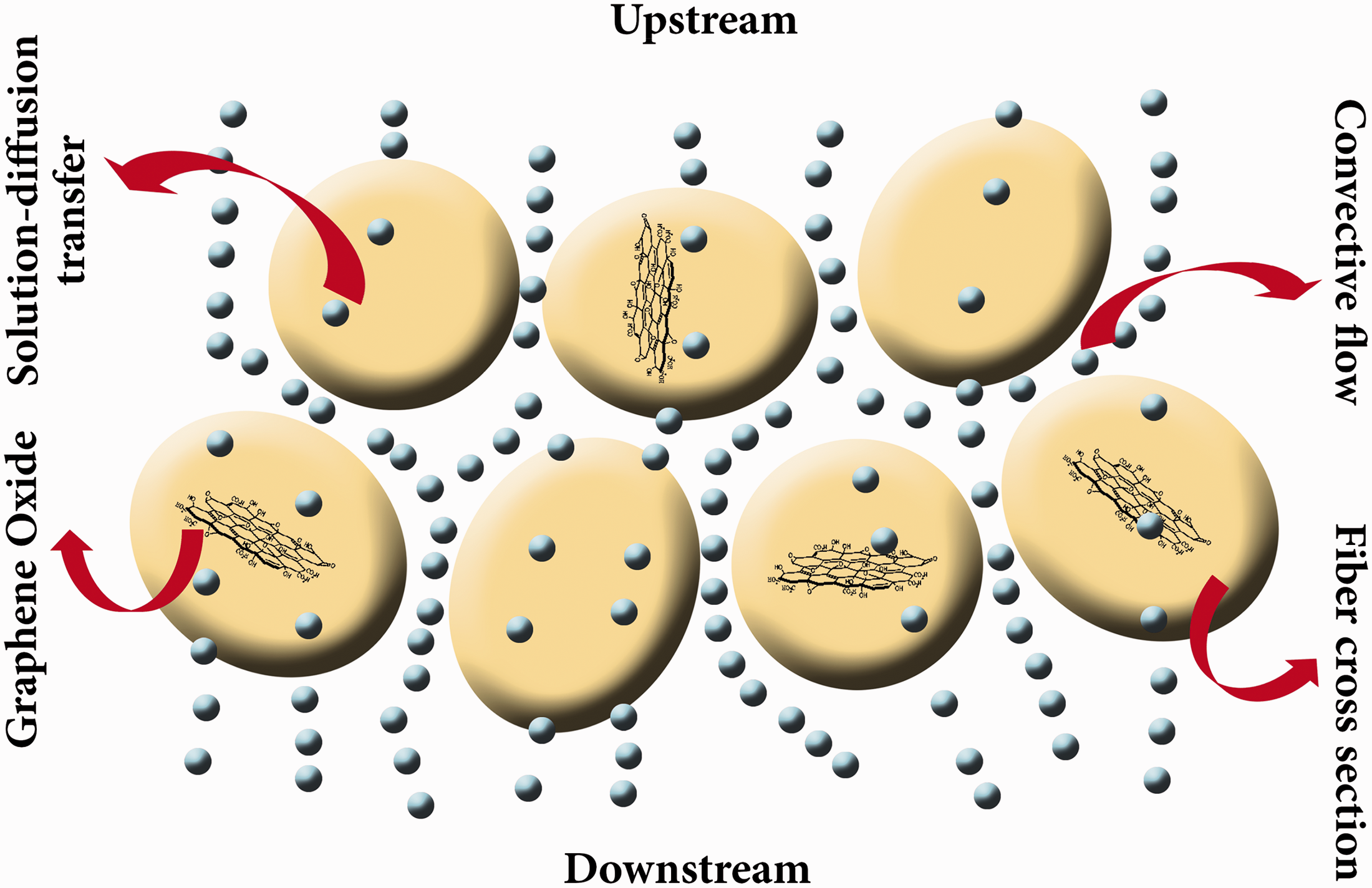
Moreover, the hydrophobic–hydrophilic behavior of membrane faces was assessed by contact angle test. Contact angle measurements on ENM’s PU face show the value of 140°, where the threshold value for hydrophobicity–hydrophilicity behavior is contact angle of 90°. The water repellency of PU nanofibers is reported by other research groups [1,6]. This comparable obtained result proves the hydrophobicity of membrane in PU sides. Instead PAMPS side of membrane is a super absorbent (with and without GO content) that measuring of contact angle is ever impossible. So the membranes show good enough dual-mode hydrophobic–hydrophilic properties which are desirable in PC applications.
Conclusion
In this paper, dual-mode hydrophilic–hydrophobic electrospun PU/P(AMPS-GO) nanofibrous membranes were fabricated and characterized. According to the FE-SEM studies, increasing the GO content leads to decrease in diameters of PAMPS nanofibers. Tensile strength of nanofibrous membrane rises from 1.4 MPa to 2.9 MPa with increasing GO content up to 0.2 wt.% and then falls. By increasing the GO content up to 0.4 wt.%, tensile modulus of the nanofibrous membranes increase up to 2.5 times greater than parallel samples without GO. However, by adding 1 g/m2 of PAMPS nanofibers to the PU, WVP reduced by 15% but increase in GO content led to more increment in permeability of membranes due to improvement in dimensional stability of ENMs. In demand, opposite hydrophobic–hydrophilic behavior was also successfully reached on two faces of ENMs by electrospinning of PU and PAMPS nanofibers, respectively. The produced nanofibrous membranes were assessed as good comparable candidates for breathable membranes used in protective clothing and wound dressing applications.
Footnotes
Acknowledgements
The authors would like to acknowledge Dr Soghra Ramazani for plotting some figures and also they thank Mrs Zahra Tafazoli for drawing schematic images of this paper.
Declaration of Conflicting Interests
The author(s) declared no potential conflicts of interest with respect to the research, authorship, and/or publication of this article.
Funding
The author(s) received no financial support for the research, authorship, and/or publication of this article.