
Abstract
In this paper, nylon 66/TiO2 composite nanofiber yarn has been developed using electrospinning method. The effect of the TiO2 nanoparticle content on the physical and tensile properties of the resulted composite nanofiber yarns has been extensively investigated using SEM, EDX, FTIR and mechanical testing machine. The probability density function is computed to model the diameter distribution of nanofibers constituent of the composite yarn for different percentages of TiO2. The addition of TiO2 nanoparticles into the electrospun composite nanofiber yarn decreases its tensile strength. The influence of thickness (diameter) and twist of the yarn on its tensile strength has been considered and the optimum conditions with improved tensile strength have been presented. Photoactivity of the composite yarns is tested against Rhodamine B (RhB). Results show that nanocomposite yarns are effective to be used as an economically and environmentally friendly photocatalyst in water remediation processes. They are not dispersed in the solution and can be removed easily without additional and costly steps of filtration or centrifuge.
Introduction
Nano materials with different dimensions (zero, one and two dimensional) have drawn great attention of researchers owing to their large specific surface area which make them appropriate for a wide variety of applications in energy storage, sensors, electronics, biomedical and photocatalyst [1]. Different methods including liquid phase deposition [2], chemical vapor deposition [3,4], ultrasonic irradiation [5], hard templates, soft template [6], centrifugal jet spinning [7], meltblowing, bicomponent spinning, forcespinning, and flash-spinning [8] have been used to synthesize one-dimensional nanostructures in the form of wires [9,10], nanotubes [11], rings [12], nanofibers [13], and so on. From these methods, electrospinning has been developed rapidly due to the versatility, ease of use, flexibility, and the ability to produce continuous nanofibers with diameters from submicron to nanometers [14]. High aspect ratio and high specific surface area of electrospun TiO2 nanofibrous mats make them a good candidate in water remediation processes. However, they need to be dispersed in the polluted water by stirring or sonication step to show a good photocatalytic activity. After water purification, a centrifuge step is additionally required to remove the catalyst from the solution [15]. Recently, fabrication of nanofiber yarns has attracted a lot of research groups due to their improved functions and mechanical properties [14–18]. Electrospun pure TiO2 nanofiber yarns have been fabricated by combining electrospinning and sol–gel method to overcome the nanofiber mat’s problems in photocatalytic tests. However, pure TiO2 nanofiber yarns need a calcination step to remove polymer and the solvent and obtain anatase phase of TiO2. Nanofibers inside the yarn also tend to shrink and become brittle during this heat treatment.
Developing composite nanofibers with the addition of the nanoparticles (NPs) to the polymer has increased the multi-functionality of the nanofibers [1,19]. They have flexibility and reflect the properties of its component (polymer and the NPs). The mechanical and chemical properties of the nanofibers vary due to the effect of intrinsic properties of the NPs and their amount used in the composition [20–23]. Different NPs have been used to fabricate electrospun composite nanofibers including Fe3O4 [24], ZnO [25], TiO2 [26], AgCl [27], CNT [28,29], and their effect on morphology and the mechanical properties of the composite nanofibers have been investigated [2–6,29–33]. On the other hand, NP inclusion in the electrospinning solution changes the viscosity and conductivity of the solution which alters the diameter of fabricated fibers and consequently affects the specific surface area of nanofibers and makes them useful for peculiar applications [30]. However, fabrication of composite nanofiber yarns composed of polymer/NP with considering the effect of NPs on the yarn structure has not been investigated yet. In this paper, composite nylon 66/TiO2 nanofiber yarns with improved mechanical and photocatalytic performance are produced. The effect of the presence of different percentages of TiO2 NPs on the physical and mechanical properties of the electrospun composite nanofiber yarns is investigated. The photocatalytic behavior of the introduced composite yarns is thoroughly considered.
Experimental
Materials
Standard TiO2 NPs (70% anatase, 30% rutile, specific surface area = 50 m2/gr), nylon 66 polymer (Mw = 30500 g mol−1), and its solvent formic acid were bought from Sigma-Aldrich, St. louis, United States.
Yarn fabrication
Nylon 66/TiO2 solutions were prepared by mixing different amounts (5, 10, 20, and 25 wt%) of TiO2 NPs with a 14 wt% nylon 66 solution prepared in formic acid and were used for the electrospinning of composite nanofiber yarns with two nozzles standing in front of each other. The schematic set-up used for making a continuous twisted nanofiber yarn was the same as it was reported before [15,18]. Nozzles with flat tipped needles (22-gauge, ID = 0.4 mm, OD = 0.7 mm) were installed at a distance of 18 cm. These syringes were fed using digitally controlled syring pump (TOP-5300, Japan) to provide a constant feed rate of 0.2 ml/h during electrospinning. DC high-voltage power supply was used to charge the needles oppositely with the same value of 17 kV.
A neutral cylinder (6 cm diameter × 30 cm length) was placed vertically at a distance of 3 cm from the middle of the distance between two nozzles. The take-up-twister unit was located at a distance of 24 cm from the syringe needles.
For inserting twist to the yarn, a rotating plate was used which was controlled by a three-phase motor and inverter to rotate from 1 to 440 r/min. Linear take-up speed could also been adjusted. Rotational speed and linear take-up speed of the rotating plate were used to insert different twist rates to the yarn.
Characterization
The diameter of composite nanofiber yarn was measured using a scanning electron microscope (Seron Technology, Model: AIS 2300C). The diameter of each specimen was the average of the diameters from five different samples. Seventy nanofiber diameters from each sample image were evaluated to obtain the average diameter of nanofibers constituting the yarn. The elemental composition of the composite nanofiber yarns was determined through energy-dispersive X-ray spectrometer (EDX) attached to the same SEM. The FT-IR spectral analysis was carried out using Perkin Elmer Spectrometer, USA.
Tensile test was carried out using an Instron Universal Testing Machine (model 5566, USA) at a crosshead speed of 5 mm/min and a gage length of 20 mm with a load cell of 2 kg to determine the mechanical properties of the as spun composite nanofiber yarns in accordance with ASTM D 3822 standard guidelines. The average of five specimens for each composite sample was measured and reported. The effect of the amount of TiO2 NPs on the tensile strength of nanofiber yarns was investigated by considering the stress–strain behavior of nanofiber yarns with different percentages of TiO2. The influence of yarn twist on tensile strength of composite nanofiber yarns was studied by considering the stress–strain behavior of composite yarns in different yarn twists of 2000, 3500, 5000 and 6500 tpm. In addition to the yarn twist, the effect of yarn diameter on its tensile strength was also investigated. Varying take-up speed (1.5 and 3.2 cm/min) was used to obtain composite yarns with different diameters. Decrease in the take-up speed and rotational speed of the twister unit was used for changing the yarn diameter while remaining the yarn twist constant, in regard to the following equation

Photocatalytic experiment
The photocatalytic activity of composite nanofiber yarns was investigated by carrying out a photodegradation study on the RhB dye with 10 ppm concentration. To prepare the nanofiber yarns for dye degradation tests, composite yarns were attached orderly on a 2 cm × 3 cm glass using a two-sided glue tape as shown in Figure 1.
Composite nanofiber yarns attached to a glass for photocatalytic test.
Then they were taken into a cubic beaker with catalyst to dye ratio of 10. A UV source (UV-A, 315 < λ < 400, 400 watt) was installed 9 cm above the cubic beaker. The lamp and the beaker were then placed in a chamber (10 × 20 × 30 cm3) covered with Al foil with a fan installed above the chamber to prevent the heating of the lamp and to stabilize the surrounding temperature during the test. A UV-Vis spectrophotometer (PD-303, APEL co, Japan) was used to measure the degradation rate at the maximum absorption wavelength of RhB (554 nm) after 1 h of UV irradiation.
Results and discussion
Composite nanofiber yarn characterization
SEM micrographs of the yarns and the nanofibers inside the composite yarns for different percentages of TiO2 NPs are shown in Figure 2. The composite yarns were constructed of a large number of nanofibers. As can be seen, TiO2 NPs were dispersed in the nanofibers of the composite yarn. Some clusters of NPs were formed among the nanofibers. TiO2 NPs in the form of dispersed or agglomerated could affect the diameter distribution of nanofibers composing composite nanofiber yarns.
SEM Images of the yarns and nanofibers inside the composite yarns for (a, b) 5% TiO2, (c, d) 10% TiO2, (e, f) 20% TiO2, and (g, h) 25% TiO2.
Average diameter of the nanofibers in the composite nylon/TiO2 yarns with different percentages of TiO2.

Statistical analysis of the data confirmed the significance of the average fiber diameter in yarns at 95% confidence level using univariate analysis of variance performed with SPSS software. Tukey’s test of the data categorized the fiber diameters into three groups. It indicated that the average diameter of the fibers composing the yarns increased with an increment in the amount of TiO2 NPs in electrospinning solution from 5 to 10 and 20 wt% which is predictable due to the increase in solution viscosity with the addition of TiO2. However, influence of higher than 20 wt% of TiO2 content to the solution was not significant on the average diameter of nanofibers.
The probability density of the nanofibers diameters for each specimen was calculated by differentiating from the fitted function to the cumulative distribution of nanofiber diameter which is shown in Figure 3. Probability density of fiber diameter showed the diameter distribution of the specimens. This method has been used earlier to model size distribution of comminution processes [35]. As can be seen in the figure, with addition of 5% of TiO2 to the solution, the diameter of the nanofibers inside the yarn was still distributed uniformly. However, increasing the amount of TiO2 to 10% and 20% increased the chance of fabricating nanofibers with greater diameters in the electrospinning which was the reason for the increase in the average diameter of the nanofibers. Increasing the chance of production of higher diameters had its effect on the diameter dispersion which reduced the uniformity of diameter distribution. The density function of nanofiber yarns with 25% of TiO2 indicated that frequency of fibers with higher diameter had increased. Increasing fiber diameter with an increased in amount of TiO2 in the electrospinning solution of nylon/TiO2 nanofibers has been reported before [31,36].
Probability density of the diameter of nanofibers inside the composite yarn for different percentages of TiO2.
The chemical composition of the as-spun composite nanofiber yarns was analyzed by EDX spectrum shown in Figure 4(a) to (d). The signals of C, N, O, and Ti were clearly observed for the composite nanofiber yarns. Ti wt.% in the EDX spectrum increased with an increase in TiO2 content of electrospinning solution which confirmed the successful embedding of NPs into nylon 66 nanofiber yarns. Au peaks in the spectrum are attributed to the gold coating of the specimens for taking SEM-EDX images.
Energy Dispersive X-ray Detector of composite nanofiber yarns with different TiO2 content. (a) 5 wt.%, (b) 10 wt.%, (c) 20 wt.%, and (d) 25 wt.%.
FTIR spectroscopy was used to identify qualitatively composition of TiO2 and nylon 66 in composite nanofiber yarns, and typical results are illustrated in Figure 5. Many absorption bands belong to organic groups such as OH and vibration bands of nylon 66. A very broad band emerges in the range of 500–700 cm−1 for all composite nanofiber yarns which is due to the vibration of Ti–O–Ti bonds in TiO2 lattice. In around 3300 cm−1 abroad, a band was observed which was related to stretching hydroxyl O–H representing water as moister. Peaks at 3085 indicated stretching of N–H. Peaks at 2926 and 2858 were related to the C–H stretching bond. Absorption peaks at 1416, 1262, and 1200 were assigned to CH2 scissoring vibration in Trans conformation, C–O stretching, and CH2 twist-wagging of nylon 66, respectively.
FTIR spectra of composite nanofiber yarns with different TiO2 content: (a) 5 wt.%, (b) 10 wt.%, (c) 20 wt.%, and (d) 25 wt.%.
Tensile behavior of composite nanofiber yarns
The tensile stress–strain behavior of composite nanofiber yarns with different percentages of TiO2 is shown in Figure 6. The composite nanofiber yarns showed less tensile stress value than the pure nylon 66 nanofiber yarns. Increasing the amount of TiO2 resulted in more decrease in the tensile strength of the composite yarns. This may be attributed to the presence of agglomerated TiO2 NPs between the polymeric chains of nylon 66 which inadvertently introduced potential weak points at the nanofiber yarns and consequently caused severe stress concentrations. This stress concentration points resulted in decreasing tensile strength of composite nanofiber yarns. Therefore, fracture of the yarn was occurred with exerting smaller forces. On the basis of this statement, it could be concluded that composite nanofiber yarns with 5% of TiO2 which had less addition of the NPs to the electrospinning solution would have less decrease in their tensile strength in comparison to other composite yarns. According to the previous study,31 the same results have been reported for composite nylon 66/TiO2 nanofiber mats which confirms the obtained results for the electrospun composite nanofiber yarns. On the other hand, addition of TiO2 to the yarn structure which increased the average diameter of the nanofibers inside the yarn might also be a reason for decreasing the yarn strength. Smaller fiber diameters resulted in higher specific surface area of the nanofibers. Consequently, the surface contact of the nanofibers increased and enhanced the electrospun nanofiber yarn strength. Generally, introducing TiO2 NPs into the nanofibers increased the strain capacity of the yarns. However, the tensile strength is very lower than pure nanofiber yarn. The nanofibers containing 5% of TiO2 NPs showed better strain capacity in comparison to other yarn samples.
Stress–strain behavior of nanocomposite yarn with different percentages of TiO2.
Yarns with 5% of TiO2 showed the best tensile strength among the composite nanofiber yarns with various percentages of TiO2. Therefore, it was chosen to consider the effect of yarn twist on its tensile strength. The stress–strain behavior of the nanofiber yarns with different twist rates is shown in Figure 7.
Stress–strain behavior of nanocomposite yarn with 5% of TiO2 with different twist rates.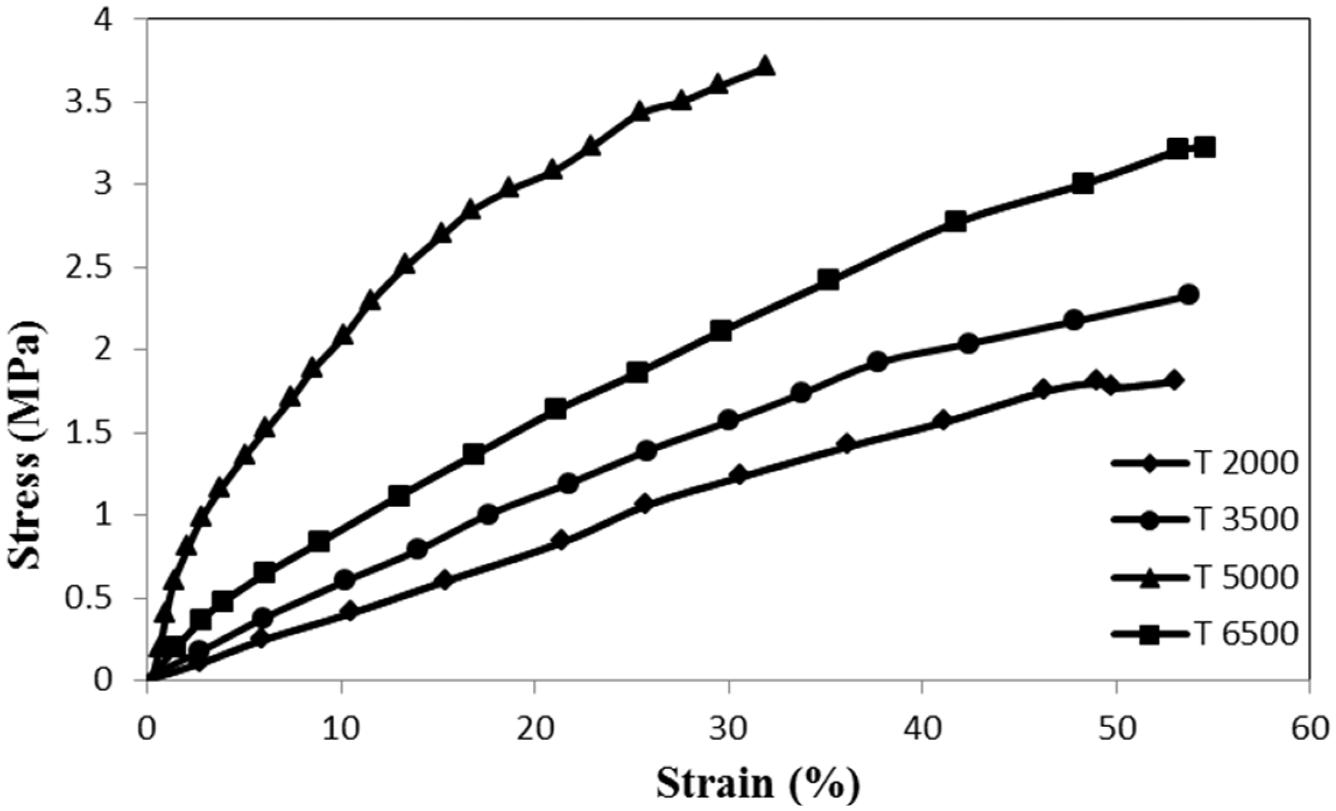
Strength properties of composite nanofiber yarns with different twist rates.
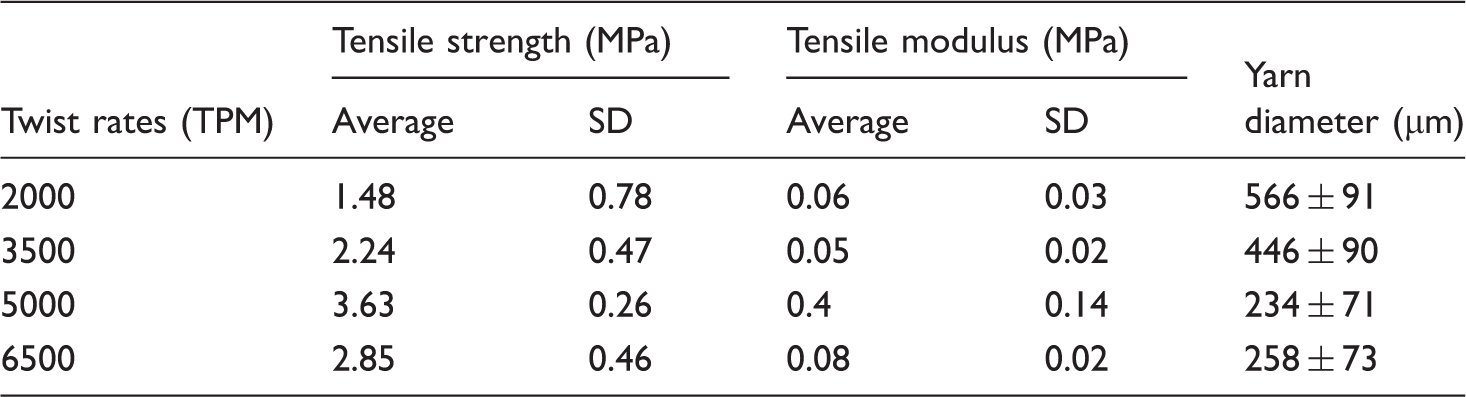
An analysis of variance showed statistically significant difference in tensile strength of the yarns with different twist rates. The results indicated that the higher strength of the composite nanofiber yarns could be obtained with the twist rate of 5000 tpm. The tensile strength of the yarn increased from 1.48 MPa at a twist rate of 2000 tpm to 3.63 MPa at a twist rate of 5000 tpm. Therefore, the strength of the yarn enhanced by increasing the twist rate from 2000 to 5000 tpm. However, more increase in the yarn twist decreased its tensile strength. For increasing the inserted yarn twist, rotational speed of the twister had to be increased. The intensity of the air flow around the take-up unit prevented fabricated fibers from settling into the spinning triangle which resulted in cutting the producing yarn. This discontinuous production due to the problems of increasing air flow resulted in yarns with less tensile strength compared to the yarns with inserted 5000 tpm twist. Other research groups have also reported an optimum point for enhancing tensile strength in their electrospun nanofiber yarns with an increase in the winding speed of the collector [37,38].
The effect of the diameter of the yarns on their tensile strength was considered by fabricating yarns at a twist rate of 5000 tpm with two different take-up speeds of 1.5 cm/min and 3.2 cm/min. The stress–strain behavior of these nanofiber yarns is shown in Figure 8.
Stress–strain behavior of composite nanofiber yarns at a twist rate of 5000 tpm with different take-up speeds.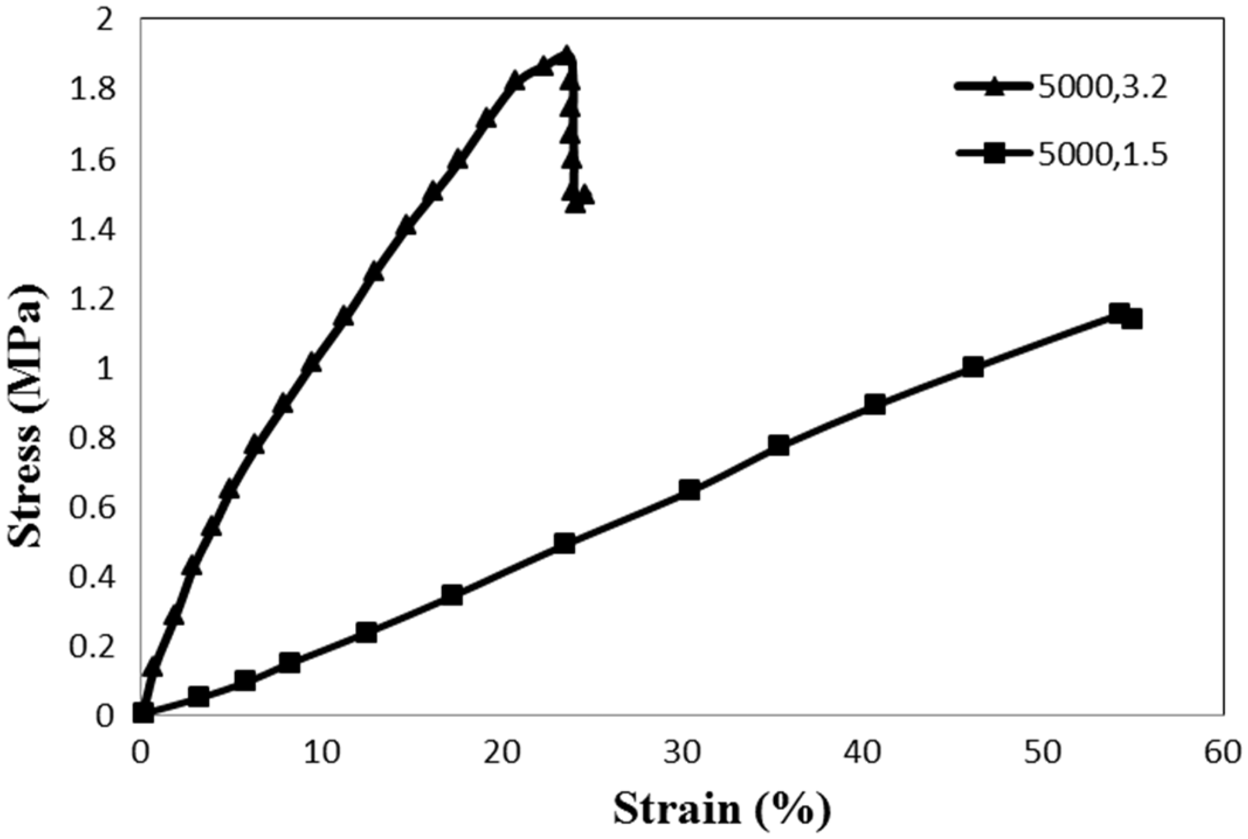
Strength properties of composite nanofiber yarns at a twist rate of 5000 tpm with different take-up speeds.

Equation (2) shows the relation between the yarn diameter (D) and twist angle (α) with yarn twist (tpm).

As it is clear from the equation, increasing the yarn diameter increased the twist angle which resulted in fiber immigration in smaller yarn length. Lower rotation speed of the twister unit was used for the smaller take-up speed to obtain the same twist rate. It resulted in smaller stress forces to the yarns and so fiber compactness beside each other in the yarn cross section decreased and consequently stress transfer between fiber bundles decreased and resulted in reduction of yarn strength.
The photo degradation profile (Absorbance change) of RhB under UV irradiation in the presence of different percentages of composite TiO2/nylon 66 nanofiber yarn is shown in Figure 9.
The photocatalytic degradation of the RhB dye with composite nanofiber yarns.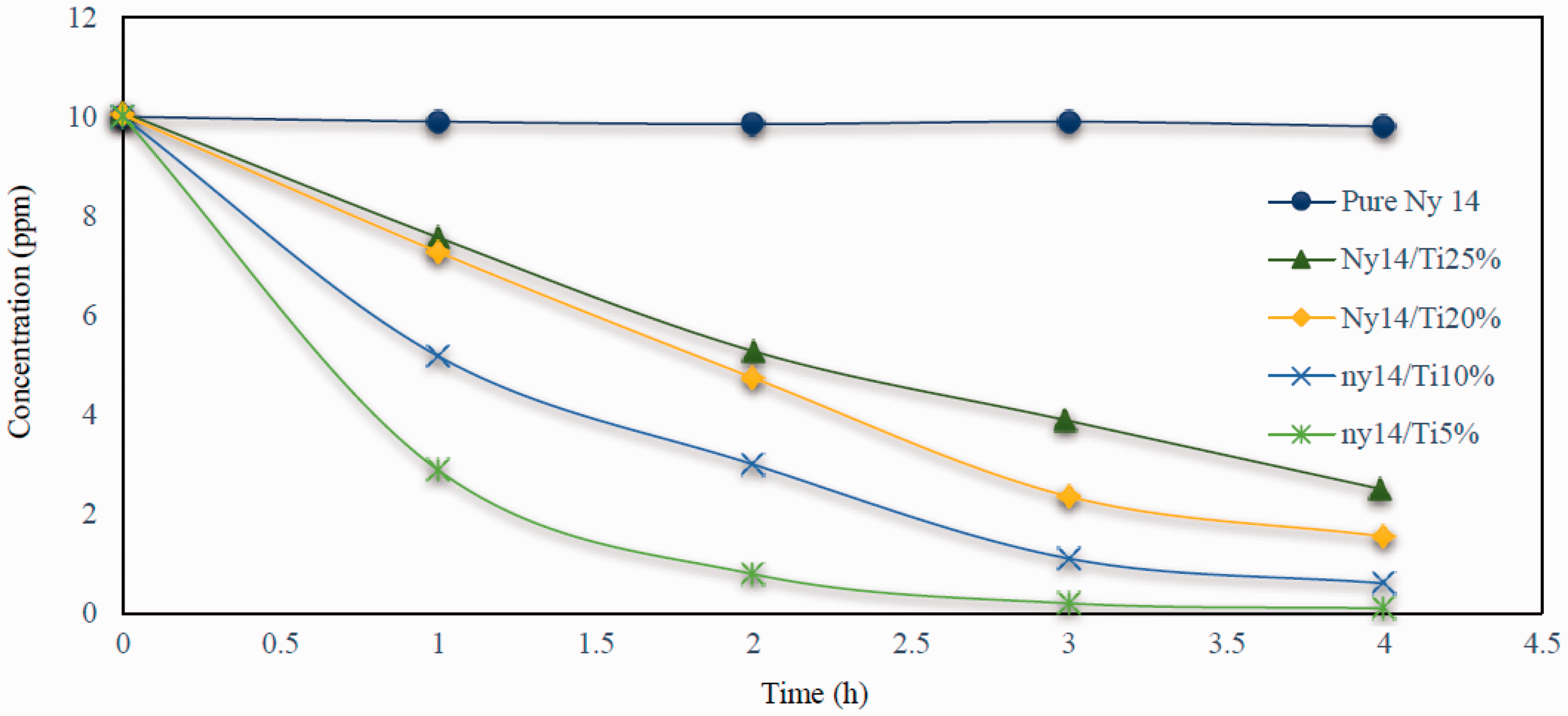
High packing density of yarns with nano structure is a factor for UV penetration and liquid mass penetration to the yarn structure. On the other hand, light could be transited from the porosity between the nanofibers in the yarn which could result in electron excitation of TiO2 NPs in inner layers of the yarn and consequently dye could be degraded not only with the NPs on the yarn surface, but also the ones in the inner part of the yarn. Therefore, composite nanofiber yarns showed high photocatalytic activity.
It was expected that increasing the TiO2 percentage in yarn would enhance its photocatalytic performance. However, it was found that decrease in TiO2 percentage intensified its photocatalytic activity and consequently faster degradation of the dye occurred. Therefore, the best degradation rate was for composite yarns with 5% of TiO2 and the lowest degradation rate was for 25% of TiO2. The diameter distribution rate of nanofibers was observed from their probability density diagram which indicated that increase in TiO2 percentage resulted in electrospun yarns with higher nanofiber diameters. This could confine the TiO2 particles in the fibers instead of standing on their surface which could not be photo activated and so could not influence the degradation of the dye. Increasing TiO2 percentage in the electrospinning solution resulted in more agglomeration of the TiO2 NPs and so they clogged between the fibers in the yarn instead of dispersing uniformly on the fiber surface. Moreover, lower fiber diameter of the yarns in minor TiO2 percentage was a reason for higher specific surface area of the yarns and so more TiO2 NPs could be in contact with the dye solution and consequently demonstrated better dye degradation rate. Composite yarns with 5% of TiO2 could degrade more than 95% of the 10 ppm RhB dye after 4 h of UV irradiation.
For considering the efficiency of composite nanofiber yarns, its photocatalytic activity was compared with pure TiO2 nanofiber yarns which was previously introduced by us [18]. Recently pure TiO2 nanofiber yarns were fabricated by combining electrospinning and sol-gel method. Calcination was used to remove the polymer and solvent. Calcined yarns consisted of pure TiO2 nanofibers with properties similar to TiO2 NPs Degussa P25 after heat treatment at 650℃ – 3 h (75% anatase–25% rutile, particle size = 23 nm). We compared dye degradation behavior of those pure TiO2 nanofiber yarns with our composite nanofiber yarns which is shown in Figure 10.
Comparison of photocatalytic activity of pure and composite nanofiber yarn.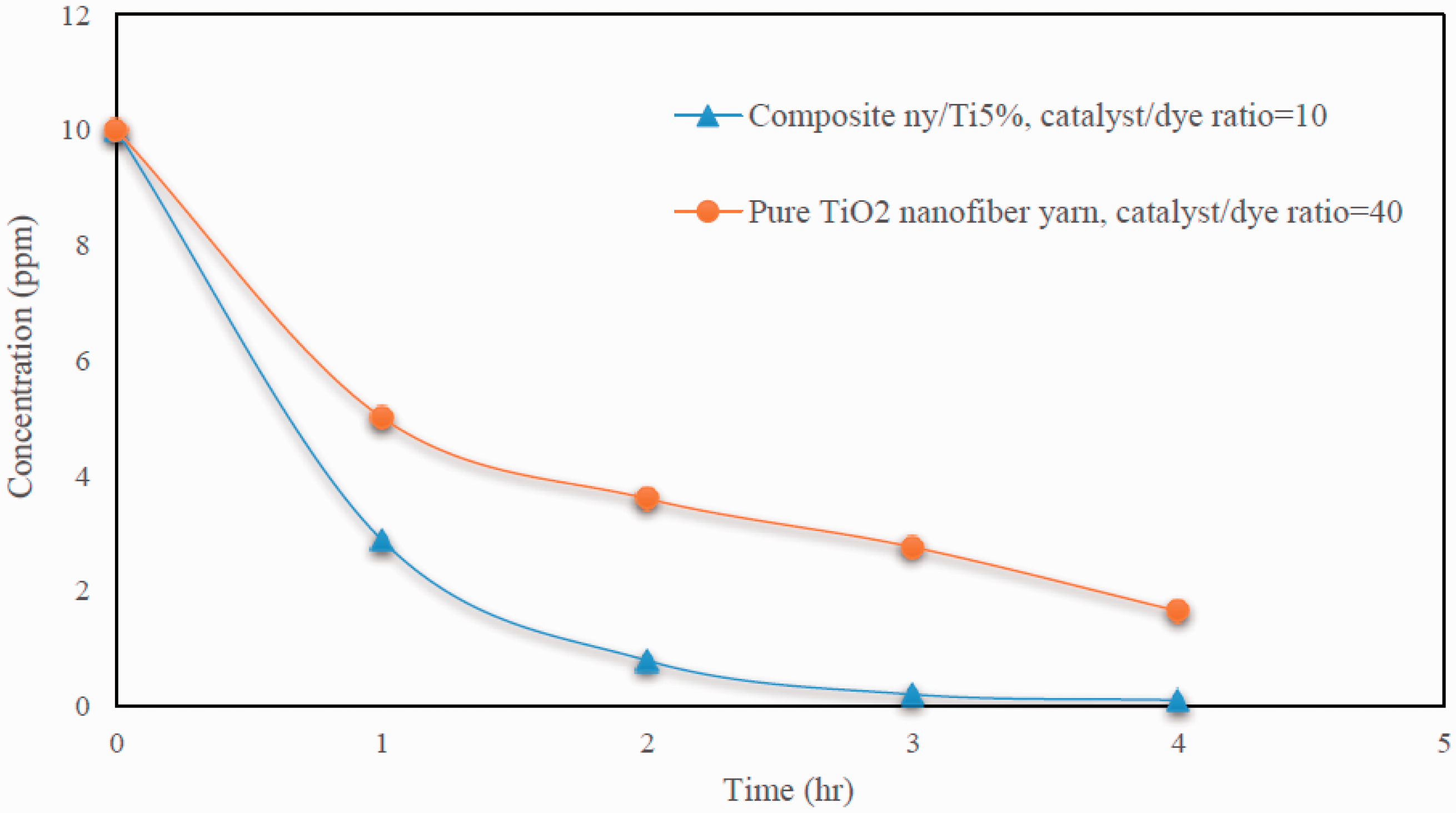
In dye degradation test of pure TiO2 nanofiber yarns, catalyst to dye weight ratio was set to 40. This ratio was reduced to four fold and set to 10 in dye degradation tests for composite nanofiber yarns. However, dye degradation behavior enhanced significantly in composite yarns which had up to four fold less amount of catalyst in the solution. They could decompose 95% of the dye from the solution after 4 h of UV irradiation compared to pure nanofiber yarns which could only degrade 82.5% of the dye at the same time.
Degussa P25 has high photocatalytic behavior. However, they still have some problems for removing them from the purified solution or their agglomeration during the test and so on which results in efforts of different research groups for stabilizing them into a substrate to overcome these problems. In composite yarns, NPs are confined into the nanofiber surface. So they do not pollute the solution. On the other hand, the catalyst has high surface area with the solution. Wicking of yarn structure and hydrophilicity of its materials result in presence of more dye around the catalyst and consequently they can be degrade. The combination of these factors makes the composite yarn an appropriate option for use of TiO2 NPs Degussa P25 for water purification processes.
Conclusions
A simple method has been used to fabricate composite nanofiber yarns of nylon 66/TiO2 using two nozzles and electrospinning method. The effect of the presence of the NPs on the properties of the nanofiber yarns has been investigated. Diameter distribution variations by different amounts of NPs in the electrospinning solution have been considered by calculating the probability density function of the nanofiber diameters. The effect of NPs on the strength of the composite nanofiber yarns has been thoroughly investigated by considering their amount, different take-up speed, and twist rates. It was found that the optimum conditions for producing composite nanofiber yarns with the best tensile strength were composing of 5% of TiO2 with twist rate of 5000 tpm and take-up speed of 1.92 m/h. The effect of the presence of the TiO2 NPs on developing their intrinsic properties to the composite nanofiber yarn has also been investigated by studying their photocatalytic activity. The TiO2 percentage plays an important role on the photocatalytic activity of composite yarns. Yarns with 5% of TiO2 had a significant photocatalytic performance and could degrade 95% of the dye from the solution after 4 h of UV irradiation. The presented composite yarns are a good candidate as a photocatalyst for industrial usage in comparison to TiO2 nanofibers and NPs which is due to their advantages given as follow:
Composite yarns are always in contact with the dye solution without dispersion in the solution.
^ Photocatalyst does not require stirring or ultrasonic for dispersion. ^ The solution is not polluted. They can be removed simply from the purified water without using additional costly processes.
^ Filtration or centrifuge steps are not required for removing the composite yarns from the solution. ^ The photocatalytic activity of the yarns can be enhanced simply by adding more composite yarns to the dye solution despite of nanofibers and NPs in which increasing the amount of catalyst is limited. Higher amount of the catalyst may reduce its activity due to some problems of agglomeration of NPs or preventing of UV light penetration.
Footnotes
Declaration of Conflicting Interests
The author(s) declared no potential conflicts of interest with respect to the research, authorship, and/or publication of this article.
Funding
The author(s) disclosed receipt of the following financial support for the research, authorship, and/or publication of this article: The authors would like to express their sincere thanks to the Iranian National Science Foundation (INSF) for the support given through research grant number of 94027400.