
Abstract
Hexadecane-polyurethane core-shell nanoweb with thermo-regulating property has potential application in technical textiles such as protective clothing. However, there are challenges in preparation of hexadecane-polyurethane core-shell nanofibers due to non-conductivity of hexadecane as well as its low viscosity. The geometry of coaxial nozzle is one of the most important process parameters which plays vital role in the formation of core-shell structured materials such as hexadecane-polyurethane nanofibers. To study the effect of coaxial nozzle geometry on success level of forming core-shell structures, coaxial nozzles with different lengths of inner nozzles were applied. Core-shell structure with suitable phase separation was formed as confirmed by scanning electron microscopy. The presence of both materials (polyurethane and hexadecane) in the nanofibrous mats was established by attenuated total reflectance-Fourier transform infrared spectroscopy. Thermal properties of the nanowebs were studied using differential scanning calorimetry and thermal gravimetric analysis. The results showed that the coaxial nozzle geometry had a significant influence on producing the core-shell structured hexadecane-polyurethane nanofibers. After obtaining core-shell structure by optimizing coaxial nozzle geometry, the core content of nanofibers was increased from 13% to 33% by adding surfactant to the core material. These results showed that the core-shell structured nanofibers with high loading of hexadecane in their core could be obtained by modifying process and materials in co-electrospinning method.
Introduction
Electrospun polyurethane (PU) mats have found their place in filtration and protective clothing applications. The prepared mats protect human body against some climatic issues such as wind, rain and harmful agents due to their barrier properties, high surface area and interconnected porosity [1–3]. Researchers have tried to modify and optimize the process and materials in electrospinning to achieve their desire functionality [4–6]. Also, theoretical research has been performed to predict the characteristics of electrospun mats [7]. On the other side, some researchers have focused to increase textiles functionality via incorporating specific materials such as phase change materials (PCMs) to get technical clothing [8–11]. PCMs could store thermal energy and release it when required during their melting/crystallization process, which increases the products’ thermal capacity. The products containing PCMs would receive the previously adsorbed energy by PCMs when the system temperature decreases. This regulating property provided by nanowebs containing PCMs could be changed when applying various types of PCMs with different melting and crystallization temperatures. Therefore, appropriate phase change temperature should be chosen to assure the storage and release of heat by PCMs in each product to get desired thermal regulation properties [12]. Paraffin waxes such as hexadecane (HD) as PCMs possess the ability of high latent energy storage. They are usually considered as candidates for employing in thermal regulating products [13].
Co-electrospinning is a powerful technique to apply for producing core-shell structured nanofibers with a non-conductive core (e.g. HD) [14]. This method is a modified version of conventional electrospinning. It is commonly used for production of core-shell structure by taking the advantage of using specific nozzle so-called coaxial nozzle [15]. The geometry of nozzles in both electrospinning methods is the most effective process parameter that affects morphology and therefore properties of the final produced nanofibers.
In conventional electrospinning, nozzle length and diameter have been reported as effective parameters which have significant impacts on morphology and diameter of the nanofibers [16]. In the case of polyamide 6 and poly(vinyl alcohol), it has been observed that the nanofibers’ diameter increases as nozzle length and its diameter increase [17,18]. In contrast, in the case of poly(methyl methacrylate) (PMMA) nanofibers, it has been shown that the above mentioned parameters could be ineffective by hoping to get different diameter and morphology [19].
In co-electrospinning, the effect of coaxial nozzle geometry on feasibility of producing core-shell structured nanofibers has been studied [20–23]. The influence of coaxial nozzle diameter on strength of the electric field and morphology of poly(sulfone amide) (PSA)/PU core-shell nanofibers were studied by Tong and Bin-Jie [20]. They reported that the larger electric field could be achieved by larger sized nozzles and also smoother surface would be obtained by co-needle with lower diameter [20]. It has been reported that for the successful fabrication of the PMMA/poly(acrylonitrile) (PAN) core-shell nanofibers, the inner nozzle must be protruded around 0.3–1 mm from the outer nozzle. It has been also shown that in the case of PMMA/PAN, core-shell jets and nanofibers could be obtained when the inner nozzle protrudes from the outer nozzle by 1/2 of its radius [21,22]. The stable and uniform core-shell structured nanofibers were produced using concave type coaxial nozzle for developing poly(vinylpyrrolidone) (PVP)-PAN core-shell nanofibers [23]. It was concluded that in coaxial nozzles, the relative length of outer and inner nozzles in forming a core-shell structure was an effective factor. In mentioned work, several values for relative length of inner nozzle and outer nozzle were examined due to different behavior of various polymers in Taylor cone [21–23].
Most research has been focused on the effect of the coaxial nozzle geometry on production possibility of the core-shell structured nanofibers containing conductive core materials. To the best of our knowledge, there is no publication considering the effect of coaxial nozzle geometry on core-shell forming with non-conductive core material such as HD. So, the major objective of this research was the evaluation of the used materials as well as process parameters impacts on successful production of core-shell nanofibers containing non-conductive component as a core. Five coaxial nozzles with different lengths of core capillaries were prepared for evaluation of the coaxial nozzle geometry impact on feasibility of producing HD (non-conductive material) and PU (conductive polymer) as core and shell, respectively. Produced core-shell nanofibers were characterized by scanning electron microscopy (SEM), attenuated total reflectance-Fourier transform infrared (ATR-FTIR), differential scanning calorimetry (DSC) and thermal gravimetric analysis (TGA). The HD content in nanofibers was increased by adding surfactant in core material and was assessed using DSC and TGA.
Experimental
Materials
Aromatic polyether–urethane (PU) (Mn = 85,000 g/mol) was purchased from Bayer Co., Germany. n-Hexadecane (HD) was supplied from Merck Chemical Co. and was used as received without further purification. DMF (dimethylformamide) and THF (tetrahydrofuran) (Sigma Aldrich, UK) were applied as PU solvents. Triton® X-100 was supplied with Panereac Co. (Spain) and was used as a surfactant.
Set up and methods
The used co-electrospinning setup consisted of a coaxial nozzle, two syringe pumps, a grounded collector screen and a high voltage power supply (Figure 1). One of the syringes was filled with shell polymer solution and another one filled with core material. The rates of core and shell feeding were controlled by syringe metering pumps. Both of syringes were connected to coaxial nozzle by capillary tubes. Five coaxial nozzles were used with different relative lengths of −0.117 mm, 0 mm, 0.117 mm, 0.229 mm and 0.364 mm between their outer and inner capillary nozzles as shown in Figure 2.
Sketch of co-electrospinning setup consists of two syringe pumps, a grounded collector screen and two syringes connected to coaxial nozzle with positive charge supplying by high voltage device. Schematic illustration of the applied coaxial nozzles with different inner nozzle lengths.

The effect of core to shell feeding rates on co-electrospinning process.

N corresponds to unstable Taylor cone-droplets falling from the coaxial nozzle tip.
Y corresponds to stable Taylor cone which was suitable for co-electrospinning.
Characterization
Nanofibers surface morphology and cross-section of nanofibrous webs were evaluated by SEM (model: CamScan MV2300, Czech & England) at 15 kV. Sample preparation for cross-section SEM images was performed by two methods: (1) breaking of nanowebs after keeping them immersed in liquid nitrogen for about 15 min and (2) cutting the nanowebs by sharp blade. Thermal properties of nanofibrous webs were studied by using DSC instrument (model: Maia-F3, Netzch, Germany). DSC thermographs were obtained for calculating PCM loading amount in core-shell nanofibers. The rate and range of heating/cooling were chosen as 10℃/min and 20–80℃ under nitrogen atmosphere, respectively. TGA tests were conducted to evaluate the mass changing in the range of 25–600℃ with the heating rate of 10℃/min under nitrogen atmosphere using thermogravimetric analysis device (model: PL, England). ATR-FTIR spectra were obtained by Fourier transform infrared spectroscopy device (Nikolet Magan-IR 560, USA) at wavenumber range of 400–4000 cm−1. Viscosity of PU solutions and HD were measured using Brookfield DV-II + Pro Viscometer.
Results and discussion
The effect of co-electrospinning process parameters
For achieving stable compound Taylor cone which leads to core-shell structured nanofibers, the core and shell solutions viscosity ratio (ηcore/ηshell) must be greater than a threshold value [24]. For obtaining threshold value for HD (as core) and PU solution (as shell), PU solutions in various concentrations from 9 wt% to 13 wt% were prepared using DMF:THF 70:30 (v:v) as solvent. It was observed that solution with concentration of 9 wt% was not appropriate for electrospinning due to its low viscosity, resulting in non-continuous jet. Concentration higher than 13 wt% was so viscose to have the ability for electrospinning. PU solutions with concentration higher than 11 wt% had the ability to form continuous jet without core injection but when core was injected, the jet cut and polymer droplet fell down from tip of coaxial nozzle. In the range of 10–11 wt%, fluid jet remained continuous with the core injection, therefore the threshold value for concentration 11 wt% (ηcore/ηshell: 3.032 cP/1756 cP) was obtained 0.0017 for co-electrospinning of PU and HD. The concentration 11 wt% was applied as an optimum value for PU solutions in all experiments.
Various shell and core feeding rates were selected and applied to optimize the ratio of core to shell feeding rates with the aim of obtaining higher HD content. Different voltage from 8 kV to 13 kV were used for the co-electrospinning process according to the ratio of core to shell feeding rates but PU concentration and DMF:THF ratio were maintained constant at 11 wt% and 70:30 (v:v), respectively (Table 1). The applied core feeding rate shown in Table 1 was without surfactant addition. Higher voltage caused instability of Taylor cone or jet splitting and lower voltage led to form fluid droplet on coaxial nozzle tip. Generally stable Taylor cone in co-electrospinning process obtains once a stationary compound cone containing core and shell fluids establishes and a continuous single composite jet originates from it.
So voltage was set to a certain value for each core to shell feeding rate ratios. The objective results showed that the maximum loading could be achieved when the ratio of the core to shell feeding rates had the value of 1:7, so this value was selected as a suitable value for the ratio of the core to shell feeding rates.
The effect of the solvent components ratio on co-electrospinning process.

DMF: dimethylformamide; THF: tetrahydrofuran.
The effect of core to shell feeding rates and distance between coaxial nozzles tips and collector screen on fibers diameter.

Confirmed by SEM.
The distance range between tip of coaxial nozzles and collector screen was selected as 13–20 cm (Table 3). According to the data of Table 3, it could be concluded that the changes of the nanofibers diameter were not noticeable during changing of distances between coaxial nozzle tip and collector screen.
The threshold value could be increased by decreasing of surface tension. In this state, viscose force exerted by shell on core surface would be able to overcome the cohesive force of core material more efficiently [24]. For evaluating the effect of surfactant adding on HD loading amount in nanofibers, Triton X-100 (1 wt%) was added to HD for decreasing core material surface tension. It was observed that the core feeding rate with the same shell feeding rate (0.05 mL/h) increased from 0.007 mL/h to 0.016 mL/h by adding surfactant. Increasing the core feeding rate more than this value caused instability of Taylor cone.
Evaluating of core-shell structure forming feasibility using different coaxial nozzles
The side-view SEM images of nanofibers prepared by five coaxial nozzles with different inner nozzle lengths have been shown in Figure 3. The images in this figure were specified by the corresponded coaxial nozzle in the same letter shown in Figure 2, for example the image “e” belonged to prepared nanofibers using coaxial nozzle E.
Side-view SEM images of prepared PU-HD nanofibers using different coaxial nozzles (A, B, C, D and E)-before SEM imaging, hexadecane was removed by soaking nanowebs in hexane for 24 h.
The side-view images in Figure 3 show that just two of coaxial nozzles with 0.177 mm (coaxial nozzle C) and 0.229 mm (coaxial nozzle B) protrusion of the inner nozzle from the outer nozzle were performed efficiently to produce core-shell structured nanofibers. These images implied that there was probability of two fluids (core and shell) mixing when core material had greater interface surface with the shell material in Taylor cones. The low viscosity of HD as well as its non-conductivity was the major reason to accelerate the mixing of two fluids.
In all applied coaxial nozzles in Figure 3, the feeding rates of 0.05 mL/h and 0.007 mL/h were selected for shell and core, respectively. Voltage was set to 8 kV and the value of 13 cm was chosen for distance between coaxial nozzles tips and collector screen.

Specification of coaxial nozzles and core fluids in Taylor cones.

Relative length between inner and outer capillaries of coaxial nozzles.
Contact radius of the core fluid in Taylor cones.
Height of core fluid in Taylor cones.
Interface surface.

Geometry parameters in Taylor cone.
The specifications of coaxial nozzles and their related Taylor cones have been reported in Table 4. It could be seen that the values of interface surfaces between core and shell fluids increased by decreasing the inner nozzles length. Increasing of the interface surfaces resulted in accelerating diffusion of core fluid to shell fluid. Therefore it was desirable to prevent the core and shell fluids mixing by reducing the core flow path into Taylor cone. In Figure 3, it was observed that the coaxial nozzle with the inner nozzle protruded 0.229 mm from the outer nozzle (coaxial nozzle B) showed the best results in forming of core-shell structured nanofibers. However, the coaxial nozzle with the higher inner nozzle length (coaxial nozzle A) was not successful in the formation of the core-shell structure because of core and shell fluids mixing at the edges of Taylor cone.
Top/side-view SEM images of prepared core-shell nanofibers using coaxial nozzle B with shell feeding rate of 0.05 mL/h and core feeding rate of 0.016 mL/h have been illustrated in Figures 5 and 6, the images showed that HD has been placed in the axis of the nanofibers and encapsulated inside the beads too. The beads filled with oil also were observed in McCann et al. [25] and Díaz et al.’s [26] work, they stated that the formation of these beads filled with oil were unavoidable due to low viscosity of oil.
Side-view SEM images (5000× and 10,000× magnified) of HD-PU core-shell nanofibers, shell and core feeding rates were 0.05 mL/h and 0.016 mL/h respectively – before SEM imaging hexadecane was removed by soaking nanowebs in hexane for 24 h. Distribution of nanofibers diameter and top-view SEM images of HD-PU core-shell nanofibers, the shell and core feeding rates were 0.05 mL/h and 0.016 mL/h respectively – before SEM imaging hexadecane was removed by soaking nanowebs in hexane for 24 h, the beads in image before soaking had filled with HD.

ATR-FTIR spectroscopy
To clarify the existence of materials in the nanofibers, ATR-FTIR analysis was conducted. The ATR-FTIR spectra of pure HD, PU and hexadecane-polyurethane (HD-PU) nanowebs have been presented in Figure 7 to prove the co-presence of PU and HD in the nanofibers. In pure HD, strong peaks at 2916 cm−1 and 2854 cm−1 represented the stretching vibration of –CH3 and –CH2– groups and the peak at 1454 cm−1 attributed to bending vibration of them. The peak at 729 cm−1 related to the rocking vibration of –CH2– group.
ATR-FTIR spectroscopy of (a) pure HD, (b) PU nanoweb and (c) HD-PU nanoweb.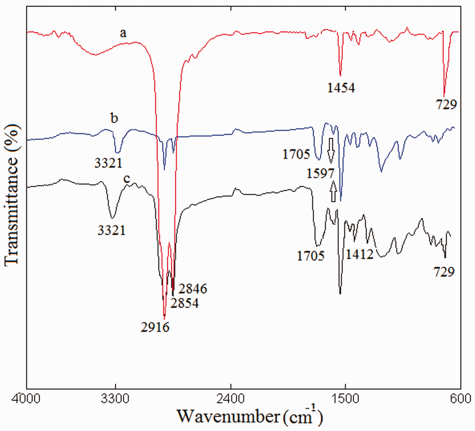
Many peaks of various intensities appeared in neat PU nanoweb sample, the strong peak around 3321 cm−1 was assigned to the stretching vibration of N–H in the urethane group. The peaks at 2916 cm−1 and 2846 cm−1 corresponded to the stretching vibration of –CH2– belonging to polyether. The peaks at 2916 cm−1 and 2846 cm−1 were the stretching vibrations of –CH2– group in state of asymmetric and symmetric, respectively. The peak at 1705 cm−1 was due to the carbonyl bond (C═O) stretching. The stretching vibrations of C═C and C–C bonds in benzene rings caused two strong peaks at 1597 cm−1 and 1412 cm−1.
In PU-HD nanoweb spectrum, all the peaks about PU were observed too but the strong intensified peaks at 2916 cm−1 and 2854 cm−1 due to stretching of –CH2– group in polyether overlapped with the peaks of stretching vibration of –CH3 and –CH2– groups in HD. The peak at 729 cm−1 demonstrated the rocking vibration of –CH2– group and it existed in the spectrum of HD-PU nanoweb while it was not available in neat PU nanoweb spectrum so it belonged to HD component of HD-PU sample, consequently the ATR-FTIR spectra results confirmed the coexistence of both materials (PU and HD) in HD-PU nanowebs.
Thermal properties of nanowebs
DSC thermograms of prepared nanowebs using different coaxial nozzles have been shown in Figure 8. In this figure, observation of the latent heat of melting (23–27 J/g) at about 18℃ could be attributed to HD which confirms the presence of HD in all nanofiber structures. However, SEM results indicated that only some samples including b and c (obtained by coaxial nozzle B and C) had core-shell structures. It could most likely be concluded that in the other samples, HD was dispersed in PU matrix without formation of core-shell structure.
DSC thermograms of obtained nanowebs using coaxial nozzles A, B, C, D and E, the shell and core feeding rates were 0.05 mL/h and 0.007 mL/h, respectively.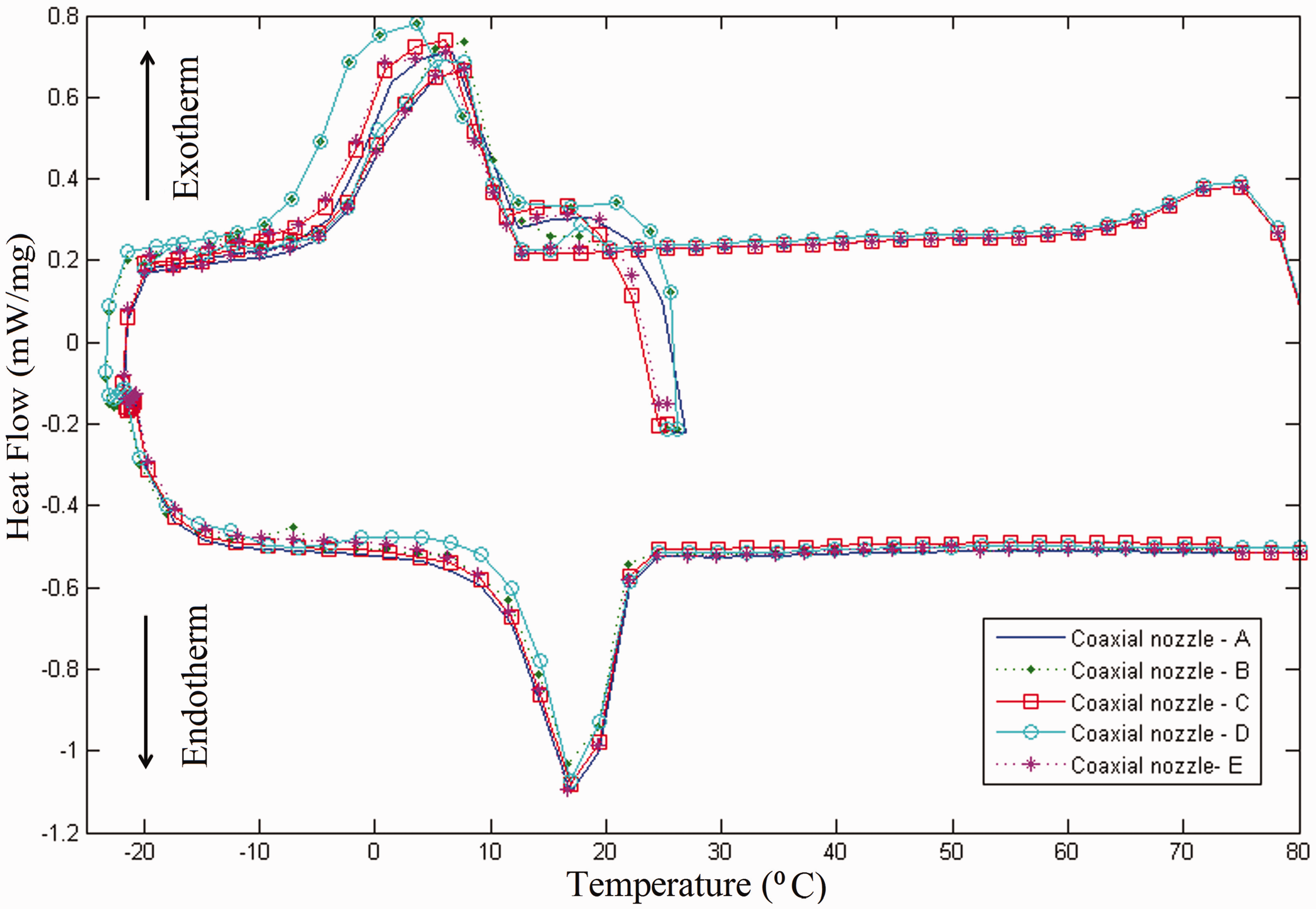
Figure 9 shows the DSC thermograms related to the preparation of core-shell HD-PU nanofibers with and without surfactant addition in their core materials. In this figure, an endothermic peak for both samples was observed at the temperature range from ∼11 to 26℃ corresponding to the latent heat of HD for changing its phase from solid to liquid. For nanofibers with pure HD (11℃), the onset point was lower compared to HD containing surfactant (12℃). This might be attributed to the effect of surfactant on improvement of crystallization structure of HD.
DSC thermograms of the HD-PU core-shell structured nanofibers with (a) HD core and (b) HD core (including surfactant), the shell feeding rates were 0.05 mL/h for both the samples but the core feeding rates were 0.007 mL/h for HD core and 0.016 mL/h for HD core with surfactant addition.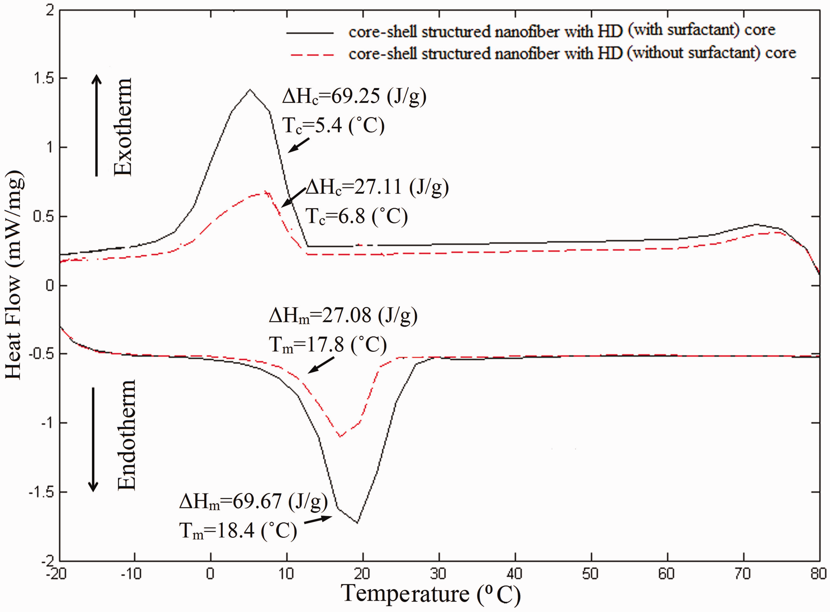
Thermal properties of core-shell structured nanofibers prepared with and without surfactant.

Hm: the latent heat of melting; ΔHc: the latent heat of crystallization; Tm: melting temperature; Tc: crystallization temperature; HD: hexadecane.
Core-shell nanofibrous web with HD core prepared with core and shell feeding rates of 0.007 mL/h and 0.05 mL/h, respectively.
Core-shell nanofibrous web with HD (including surfactant) core prepared with core and shell feeding rates of 0.016 mL/h and 0.05 mL/h, respectively.
HD (used as core of nanofibers).
Weight loss ranging from 100 to 200℃.
The mats containing these nanofibers with the maximum heat storage capacities of ∼69 J/g could be used as technical layers or breathable barriers in thermo-regulating protective clothing. As can be seen in Table 5 and Figure 9, Tm of the nanofibers containing HD in their cores was slightly lower than that of the core material, HD (20℃). However the nanofibers containing HD changed its phase at about 18℃, this temperature is in the range of human comfort zone. So, the produced mats would be a potential candidate for using in clothing.
The capability of thermal energy storage or thermal regulating efficiency (HD loading amount) could be calculated from the ratio of melting enthalpy of nanowebs to melting enthalpy of HD (213 J/g) [27,28]. The thermal regulating efficiency of nanofibers with HD and HD core containing surfactant was calculated from DSC thermograms shown in Figure 9 which were 13% and 33%, respectively.
In literatures, the maximum loading of HD in core-shell PVP-TiO2 has been reported as 31% [25]. However, Wang et al. could load 10% of HD in the core of microfibers [29]. In this work by optimizing the co-electrospinning process parameters such as coaxial nozzle geometry and materials adding, the maximum loading was obtained as 33% in the core of PU nanofibers.
TGA thermograms and their first derivatives (DTG) of core-shell structured nanofibers with HD and HD contained surfactant cores and simple PU nanofibers (without core) were obtained and have been presented in Figure 10. In these curves, two major steps of weight loss were observed in temperatures ranges of 100–200℃ and 300–500℃. The earlier loss in the temperature range of 100–200℃ corresponded to evaporation of HD and the later in 300–500℃ attributed to PU decomposition. The weight loss of 42% and 22% for HD evaporation was observed for nanofibers prepared by core containing surfactant and without it, respectively. According to initially weight of core-shell nanofibrous (12.3429 g) and 4.8% remaining sample mass (Figure 10, curve c), the weight of remained mass was obtained about 0.6 g for core-shell nanofibers with HD included surfactant in their cores. The capital letters in DTG curves belong to the same letters in TGA thermograms. The DTG curves showed some peaks that the range of occurring them were the same as weight loss steps in TGA thermograms, for example, the peaks of core-shell nanofibers with HD and HD containing surfactant core were observed in ranges of 100–200℃ (maximum at 195℃) and 300–500℃ (maximum at 347℃) in DTG curves, the ranges of TGA changes were 100–200℃ and 300–500℃ too. Similar to TGA analysis, the peak at 195℃ belonged to HD evaporation and the peak at 347℃ attributed to PU decomposition. The simple PU nanofibers showed only one broad peak at 358℃ related to PU decomposition. So, TGA thermograms validated the presence of noticeable amount of HD in core-shell structured nanofibers with injection of HD contained surfactant as core.
TGA thermograms and DTG curves of (a and A) the PU nanofibers (without core), (b and B) core-shell nanofibers with HD core and (c and C) core-shell nanofibers with HD core (including surfactant).
Thermal stability of a polymer could be interpreted by TGA analysis [30]. As shown in Figure 10 and Table 5, no significant weight loss before 100℃ was detected, therefore, this layer would be appropriate for using in climate conditions which temperature would not exceed 60℃. In other words, the prepared core-shell nanofibers have a good thermal stability in common climate.
Conclusions
The impact of materials and process parameters were investigated for successful production of HD-PU core-shell nanofibers. After evaluating and determining of the general materials and process parameters such as concentration, voltage, distance between coaxial nozzle and screen collector, core to shell feeding rates in co-electrospinning of HD-PU, two specialized parameters including coaxial nozzle geometry as a process parameter and surfactant addition in core content as a material parameter in success level of core-shell nanofibers formation were studied in details. Five coaxial nozzles with different lengths of inner nozzles were prepared and the morphology and thermal properties of the obtained nanowebs were studied using these coaxial nozzles. ATR-FTIR, DSC, TGA and DTG results confirmed the presence of HD and PU in nanowebs. Side-view SEM images verified the formation of core-shell structure for those nanowebs which were prepared by the coaxial nozzles with inner nozzle protruded from the outer nozzle in around 0.117 mm and 0.229 mm. It was found that, employing inappropriate nozzle geometry would increase the probability of core and shell fluids mixing in Taylor cone due to non-conductivity and low viscosity of HD and contact between core and shell fluids in Taylor cone. The results also indicated that by addition of surfactant in core material, the HD loading amount in core-shell nanofibers increased about 33% (from 13% without surfactant addition). So according to these results, the core-shell structured HD-PU nanofibers could be produced in controlled conditions with noticeable content of HD (non-conductive material) by modifying co-electrospinning process and materials parameters.
So, modification of process and materials parameters in co-electrospinning is the first and essential step for successful production of core-shell nanofibers with non-conductive cores that should be considered.
Footnotes
Declaration of Conflicting Interests
The author(s) declared no potential conflicts of interest with respect to the research, authorship, and/or publication of this article.
Funding
The author(s) received no financial support for the research, authorship, and/or publication of this article.