
Abstract
Extensive use of composite materials leads to an increase in waste materials. Therefore, it is necessary to find a proper way to recycle the composites. In this research, the powder waste of carbon-epoxy resin composites collected from the cutting and grinding process have been added into glass fiber reinforced phenolic resin composite during the preparation process in order to enhance some mechanical characteristics. Thermal behavior, tensile and flexural properties of adding powder composites have been analyzed. Results show that adding powder waste in a certain proportional range can improve the performance of the new composites.
Introduction
Because of the outstanding properties of carbon fiber reinforced plastic (CFRP), fiber reinforced polymers are widely used in many areas [1]. To reduce the body mass and save fuel consumption, carbon fiber reinforced composite material has become the first choice in the field of aerospace and transportation industry in recent years. This excellent material develops very fast in the promotion of energy saving and emission reduction regulations. The waste product that comes as a result of the rapid development and mass production of CFRP can always be recycled, reused. This can reduce the environmental pollution decomposition pressure.
With CFRP's extensive use, it is challengeable to recycle cutting waste and used materials of CFRP, including discarded cars and some other application materials. There are mainly two kinds of recycling method-chemical and physical method. The chemical method uses mainly pyrolysis and solvent method, whereas the physical method is mainly mechanical crushing. The method of pyrolysis recycling means the composites will decompose into fiber and resin under certain conditions. But for a large size of impurities within the waste product, the performance of stability and the quality of the recycled fiber reduces drastically. Also, it needs plenty of heat energy. Solvent recovery method is a method of separating and recovering the matrix resin and fiber under certain conditions. This method is safe in operation and it can generate clean fibers, but the reaction time is long. Physical method relies mainly on machinery and equipment, by applying a mechanical force, the thermosetting resin composite crushes or is chopped. Physical method cannot recycle carbon fiber efficiently, and it is only suitable for the composite materials, which are not polluted, but physical method operates easily and it produces no pollutant.
The literature indicates that some waste from the manufacturing of composites can be reused and this kind of waste is clean. Powder waste obtained in manufacturing process can be added into matrix. The Company Carbontek S.L., added powder waste from the manufacturing process, mainly from cutting process, into matrix to reduce the waste material, and if possible, change the mechanical properties of new composites. Thomas et al. [2] evaluated the effects of the incorporation of different percentages of this powder waste on the mechanical properties of recycled compounds. The conclusion was that powder waste can be used as a new reinforcing phase in hybrid composites to improving its mechanical characteristics.
Shokrieh et al. [3] studied the effects of multi-walled carbon nanotubes (MWCNTs) on the thermal residual stresses in polymeric fibrous composites. Results showed that MWCNTs could reduce the residual stresses in laminated polymer composites, both in micro and macro levels. Mannov et al. [4] have proved reduction in compressive strength after impact in fiber reinforced polymer composites with thermally grapheme oxide by matrix modification.
The preparation of waste material which was for input to the processes is a critical stage. Turner et al. [5] have developed a process that provides clean, high quality fibers with good mechanical property retention, this process is based on a fluidized bed. Kennerley et al. [6] and Pickering et al. [7] also contributed to a fluidized bed process in order to recover the reinforcing fibers from the scraps of thermoset composites. Some authors [8–10] have studied the effects of silica nanoparticles incorporated into epoxy matrixes. Results show that there is no negative effect on the fiber–matrix interfacial bonding strength.
Xu developed a method which can recycle fibers of high quality from carbon fiber/epoxy composites. It was realized that the degradation rate of epoxy resin was 90% and the strength of filament remains was more than 95% of its original strength. Bai et al. [11] studied another chemical method of recycling carbon fiber from epoxy resin in oxygen within supercritical water. Some other authors also wrote literatures about recycling of CFRP in water [12]. All these methods of recycling and reusing obsolete composites can produce a high-quality material.
Upon critical observation and evaluations from the above, it is clear that some mechanical and chemical recycling methods require strict conditions. In this article, an easy mechanical method was used to recycle CFRP, the powder obtained from CFRP was used to make new composite and some mechanical properties were studied.
Material and methods
Materials and sample preparation
The powder waste was obtained from the cutting and grinding process of CFRP, which were incorporated into the phenolic matrix phase. Because of the glass fiber and phenolic resin are cheaper, the newly prepared composites were made by glass fiber and phenolic resin. Newly prepared composites do not need much strength, using glass fiber and phenolic resin can totally show the differences led by different powder waste adding proportion.
The cutting and grinding process took place under a closed hood, which can prevent the powder from floating into the air, powder waste can also be protected from being polluted. Filters were used to collect the powder. Figure 1 shows the leftovers after cutting and grinding. The leftovers were usually land filled or used next time. Figure 2 shows the powder waste. Because of particle size differences of the powder, the powder needed to be sieved to remove the large particles present in the powder waste, because experimental error would be made. The powder which was sieved under 80 µm were used. To reduce the increasing manufacturing costs, no further treatment was required.
Leftovers after cutting and grinding. Powder waste generated by grinding and cutting process.

The main objective of this article is to demonstrate the effects of the addition of powder to the resin in the preparation of composite materials. There are three kinds of powder waste, all the powder was evaluated and compared, in order to find a proper powder added into new composites. Each kind of collected powder is divided into three groups. Powder was measured by Master Min Granulometer. Particle size of the powder was measured according to the light scattering theory, particle can make laser light scattering. Figure 3 shows three group of diameter measurement data and the powder was from carbon fiber epoxy plastics (Type A). The powder with 28.2 µm size takes up 33.8% of the first group of powder sample; powder with 43.8 µm size takes up 36.3% of the second group of powder sample, and powder with 58.8 µm size takes up 36.0% of the third group of powder sample. The particle diameter of the powder varies from 21.0 µm to 78.8 µm, which is nearly 35%, and its size varies from 28.2 to 58.8 µm. The Type “A” powder was seen to be fine. In this experiment, carbon fiber epoxy plastics’ powder is used.
Powder of different particle diameter and its proportion, powder waste from composite materials prepared by carbon fiber and epoxy resin (Type A).
Figures 4 and 5 show the other two kinds of powder, glass fiber reinforced plastics powder and carbon fiber phenolic plastics, respectively. Under the same deformation conditions, different composites had different particle sizes. Compared with the other powders (Types B and C), the diameter of Type “A” has a lower order of magnitude. It is much smaller than that of Types B and C in size. Type C has the same particle size as Type B but takes up well-proportioned than the other two powders. Type “B” has an unevenly distribution and the size of its particle diameter is the largest among three powders. Using powder Type “A” in the preparation process of composite materials is easier than the other two powder types. Smaller sizes of powder waste were distributed uniformly during the resin import process, making it easier to flow with the resin. How the Type “A” powder waste affects the material’s mechanical properties and thermal behavior was analyzed.
Powder of different particle diameter and its proportion, powder waste from composite materials prepared by glass fiber and phenolic resin (Type B). Powder of different particle diameter and its proportion, powder waste from composite materials prepared by carbon fiber and phenolic resin (Type C).

Powder waste as shown in Figure 2 was collected under a hood. The composite after grinding and cutting can be preserved in a long period of time and it can be used to further up some other research studies. But the powder waste must be sealed properly, so as to prevent it from absorbing moisture from the air. From Figure 2, the powder is seen as gray. Since the carbon fiber is black, the corresponding composite is also black. The same happens to the powder theoretically, the powder presents gray color, which is due to the diffused reflection, which unlike the carbon fiber. The fine carbon fiber remains in the powder, presents a metallic luster can be seen as some shiny particles. The powder can absorb moisture in the air, which adds an additional weight to the powder. Because of this property of the powder, the collected powder should be added to the resin immediately or must be preserved in a sealed environment as said earlier in order to keep constant weight.
The reinforcing body of the composite material is glass fiber. Figure 6 shows the glass fiber fabric. In the picture, the darker colored parts of the fabric indicate glass fiber multifilament, and the brighter parts, a bundle yarn. The fabric is a four axial glass fiber warp knitted fabric with the main body made of four glass fiber layers, which four layer stacks together by different axis (quad-axis). Reinforcement used in the experiment are two pieces of fabrics, which is eight layers glass fiber. When observed from the front as shown in Figure 7, the glass fiber (the white color line) of the first layer of the fabric is arranged vertically (0°); the second layer arranged in 45°; the third arranged in 90°; and the last layer in 135°(or −45°). Quad-axis arrangement ensures the stability of the fabric in each direction. From the thickness view in Figure 8, the glass fiber is placed in different orientations. Since polyester yarn (PET) has a higher strength, the four layers fibers were bundled with polyester multifilament. The image appears to be a polyester yarn produced by knitting method, the pad digital of the bundle yarn goes 1-0/1-2//, this can make all glass fiber fixed firmly.
Physical photograph of four axial fabric (0°/+45°/90°/−45°). Multi-axial (quad-axis) structure diagram (front view). Multi-axial (quad-axis) structure diagram (through-thickness view).


After characterizing the powder waste, they were collected and added into the phenolic resin (Ashland 194), which was supplied by Ashland Company. The proportions for the addition of the powder waste were 1%, 3%, and 5% wt. The resin and powder waste were mixed and stirring for 24 h. The color of resin with powder is slightly different from the pure resin.
Physical properties and thermal behavior
Specimens with size 100 mm × 15 mm × 2 mm for bending experimental condition were used to determine the volume density. It was found that the density of the composites, increased slightly with the addition of powder waste. Figure 9 shows four sheet specimens (for bending tests) containing 0%, 1%, 3%, and 5% wt. of powder waste.
Detail of four sheet specimens (0 wt. %, 1 wt. %, 3 wt. %, and 5 wt. %).
A test of relationship between the quality of the newly prepared composites and its temperature were carried out in a fully enclosed atmosphere. The thermal behavior of the sample by different powder waste ratio was measured by using thermogravimetric (TGA), a system with ca. 3 mg powder waste sample in nitrogen atmosphere. TGA was carried out in an inactive environment, with a TGA system and a heating rate of 20℃/min.
Mechanical properties
A three-point bending test and tensile test were carried out on an Instron universal testing machine. Figure 10 shows the machine. Twelve sheet specimens with size (100 mm × 15 mm × 2 mm) for three-point bending were tested. Another 12 sheet specimens with same sizes were used for tensile test. Figure 9 shows specimens for the tests and computer model specimen.
Instron Universal Machine.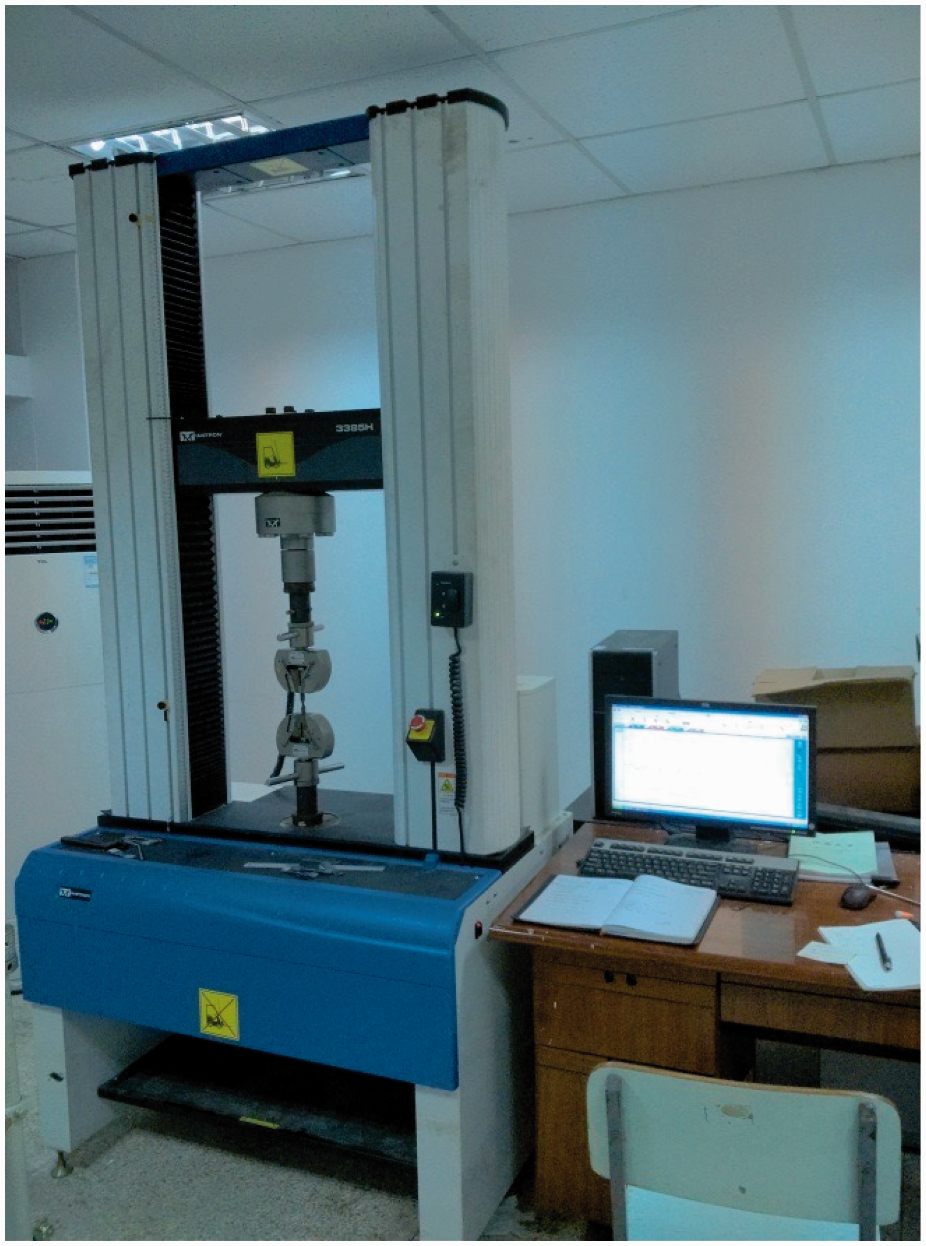
Experimental procedure and testing methods
Tensile and bending performance tests were carried out using Instron Universal Machine (as shown in Figure 10) with a statics load sensor and Instron Bluehill software. In general, 24 sheet specimens with different proportion of powder waste were tested using the machine. Figure 11 shows four specimens. Each specimen has the same size (100 mm × 15 mm × 2 mm), and a cut of 10 mm width in the middle. The specimens were curved in the middle to put much concentration on the stress.
Detail of specimens for tensile and tensile tests.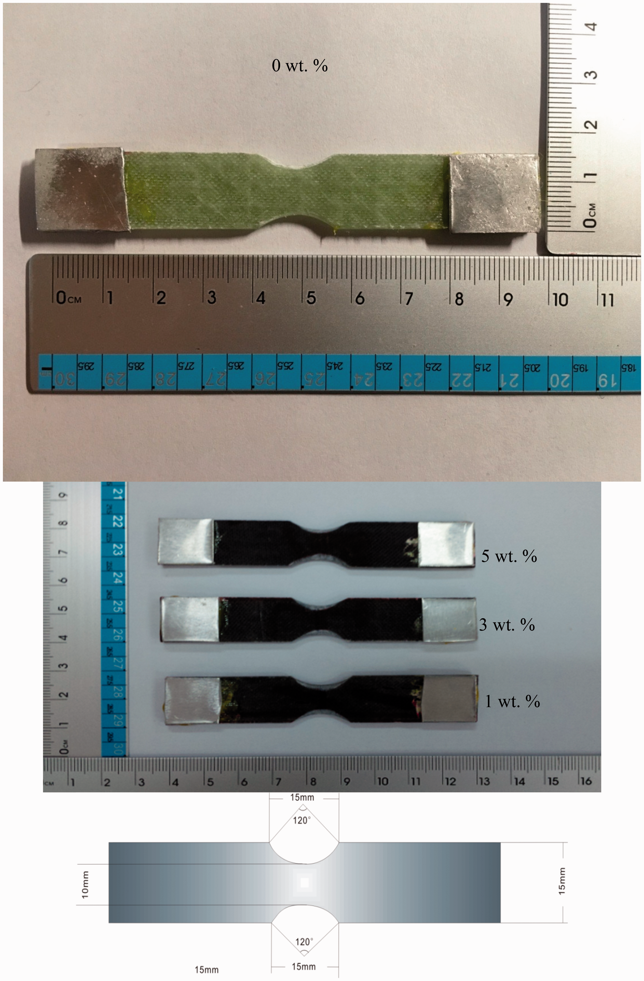
Results and discussions
Manufacturing
Adding powder waste into the thermosetting resin, increased remarkably the fluid viscosity of the mixture. Thomas et al. [8] studied the viscosity of a similar mixture, but the additions beyond 20% wt. couldn't be studied due to the great loss of fluidity. It takes a long time to mix and stir the mixture, in order to ensure an evenly distribution of powder waste residue properly in the matrix phase. The use of Ashland 194 resin demands a lower percentage of V388 hardening agent (much less viscosity). In view of this, during the mixing procedure, a lengthy time was taking in mixing and stirring and also a hardening agent was used properly. The mixture includes resin, hardening agent, and powder waste. Adopting a low mixing ratio (1%, 3%, and 5% wt.) avoids uneven mixing and the powder waste has little effect on the viscosity.
Physical properties and thermal behavior
Figures 9 and 11 show the dimension of the composite for bending and tensile test. The length of the materials is 100 mm, and the width is 15 mm. The difference between the two materials is that the composites for tensile tests were cut in, 10 mm wide at the middle in order to put much concentration on the stress. From the image of the actual object, the color of the composites with 3% wt. powder waste were darker than the 1% wt., so was the same with the 5% wt. With increase in the proportion of powder waste, the transmittance of the specimens becomes poor, and the powder can be seen under the light through the newly prepared composites.
The weight was recorded during the process of which the heating temperature was 20℃/min, and the heating temperature ranges between 20℃ and 900℃. Figures 12 to 15 reveal the results of thermal behavior test. For pure glass-resin specimen, thermal decomposition happens at 360℃, and the weight loss was around 27.5%, which is lower than the specimen with resin-carbon powder waste. The specimens with powder waste depolymerizes at 400℃, which is 40℃ higher than pure glass-resin specimens. It can be seen in the figures that the weight loss of the specimens with powder waste 1% wt. is around 50%, the specimens with powder waste 3% wt. is around 42% and the specimens with powder waste 5% wt. is 42%.
TGA/DTG curves of the newly prepared composites (0% powder waste addition). TGA/DTG curves of the newly prepared composites (1% powder waste addition). TGA/DTG curves of the newly prepared composites (3% powder waste addition). TGA/DTG curves of the newly prepared composites (5% powder waste addition).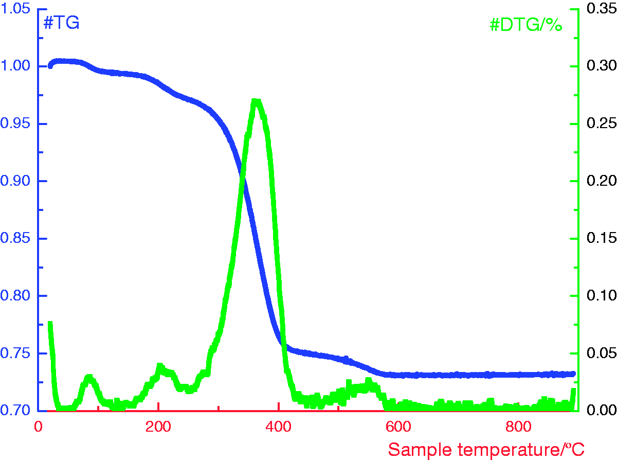


From the figures, it could be seen that the addition of extra powder waste can improve the thermal decomposition temperature of the original specimens. From this experiment, adding a small amount of powder can improve decomposition temperature by 40℃ higher. But adding powder waste can decrease the thermal stability of the material. Besides, the thermal decomposition of material changes by different addition proportion. In this experiment, it can be concluded that the specimens with powder waste of 1% wt. are nearly two times than the original pure ones by weight loss. Also with the increase in the weight proportion by 3% wt. of powder waste, the ratio of weight loss decreases, but improving slightly the thermal stability of the material. Until adding powder waste at 5% wt., weight loss did not change. But the thermal decomposition temperature increases slightly.
Mechanical properties
Figures 16 and 17 and Table 1 show the results of the tensile modulus of elasticity and bending modulus of elastic (MPa), Young's modulus was analyzed.
Stress–strain curve of tensile test with different powder addition ratio. Stress–strain curve of bending test with different powder addition ratio. Results of the mechanical tests.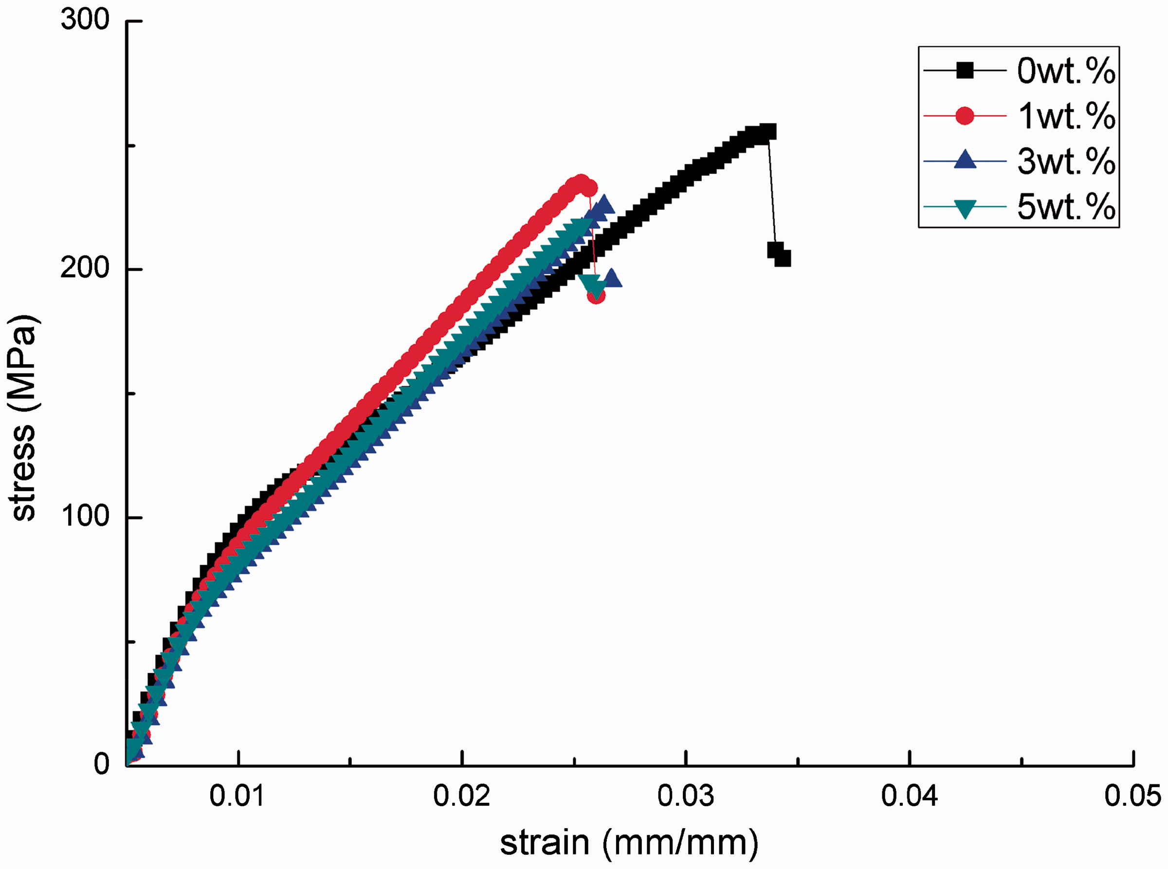


Figure 11 shows the different kinds of specimens for tensile test. It is concluded that the tensile and flexural behavior is improved when increasing the filling volume fraction [13]. From the result of Figure 16 and Table 1, the specimens with 1% wt. powder addition ratio as compared with the specimen without powder waste has a slightly better tensile property. The specimens with the addition of 1 wt. % powder waste provided a 23138.14 MPa tensile modulus of elasticity, the pure ones were 22167.80 MPa. The increase percentage therefore is 4.38%. When the proportion of powder waste increases to 3% wt., the tensile modulus of elastic in the composites is 18886.67 MPa, providing a 14.80% loss in the tensile strength than the pure ones. Compared with the pure ones, the specimens with 5% wt. (18703.97 MPa) powder waste provided only a 15.63% loss. From the figures obtained, the elongation at break of the pure specimens is longer than the newly prepared composites, it could be concluded that adding powder waste makes composites brittle.
Figure 9 shows specimens for bending test, whereas Table 1 shows the bending modulus of elasticity of specimens with different powder addition proportion. It can be found that specimens with the addition of 1% wt. of powder waste provided a 1050.24 MPa bending modulus of elasticity, whereas the pure ones’ is 887.15 MPa, indicating a bending strength increased by 15.53%. When proportion of powder waste increases to 3% wt., the bending elastic modulus of the composites is 950.89 MPa, the increase in strength becomes 7.18% more than the pure ones. The bending modulus of elasticity of the specimens with 5% wt. powder waste is 896.40 MPa, which has a 1.04% increase than the pure one. The specimens with 5% wt. powder waste have nearly the same maximum bending strength with the pure ones.
Compared with the increase of the tensile strength, the contribution of powder to the increase of bending strength is more obvious. The maximum improvement of the tensile properties is 4.38%, whereas for the bending properties is 15.53%.
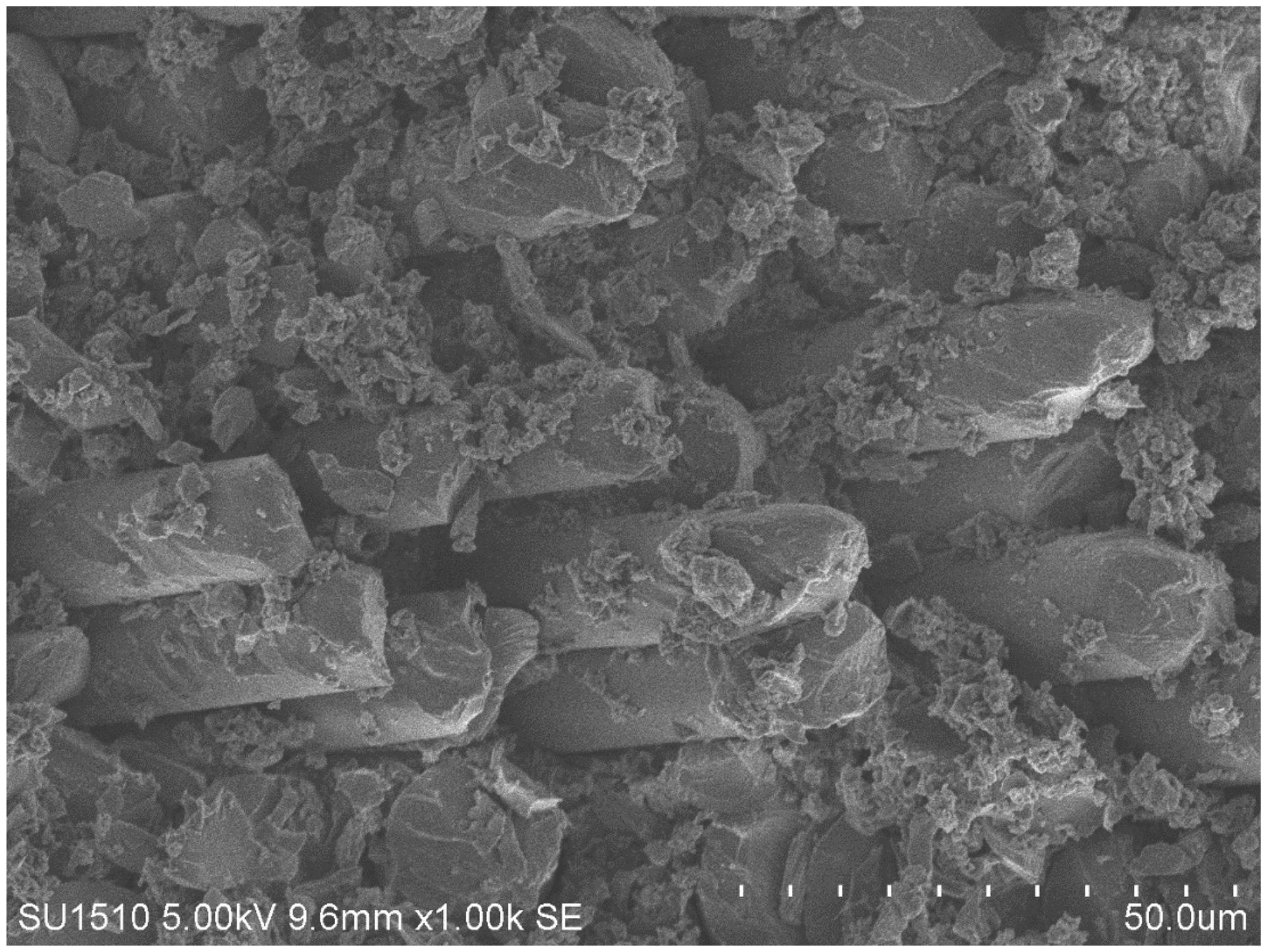
The specimens were observed using a scanning electron microscope. Figures 18 through 25 show the SEM images of the specimens with different powder waste addition (0%, 1%, 3%, and 5% wt.). It can be seen from the images that the river lines are very smooth, which the characteristics of the glass fiber is. The particulate matter around the glass fiber indicates that the powder waste make the internal interface of the material rough. From the images, the size of the particulate matter is nearly 50 µm. The observed results were in agreement with the previous particle size test results. It is obvious that with the increase of the proportion of the powder waste, the arrangement density of the particles in the images increased.
SEM image of the composite with 0% powder waste addition.
Figures 22 through 25 show the cross-sectional SEM images, the voids variation at different quantities of powder can be seen. From the images, the circular part in the images is glass fiber cross-section. Around the glass fiber, resin and powder mixed together. The particle size of powder is also under 80 µm, it is consistent with the observation and testing result. It is obvious that the voids between powders get smaller by the increasing quantities of powder.
SEM image of the composite with 1% powder waste addition. SEM image of the composite with 3% powder waste addition. SEM image of the composite with 5% powder waste addition. SEM image of the composite with 0% powder waste addition (cross-sectional). SEM image of the composite with 1% powder waste addition (cross-sectional). SEM image of the composite with 3% powder waste addition (cross-sectional). SEM image of the composite with 5% powder waste addition (cross-sectional). Specimens after tensile and bending tests (0 wt. %). Specimens after tensile and bending tests (1 wt. %). Specimens after tensile and bending tests (3 wt. %).


With the addition of powder waste, the mechanical properties of the composite increase first and then decreases in a certain range. Therefore, it can be concluded that adding a small amount of powder waste can improve the tensile and flexural properties of the composites. Furthermore, the severity of the decreases happened with increasing proportion of powder. It includes that the tensile mechanical properties of composites depends on the acting force between the reinforcement and the matrix. The stronger the acting force, the better the performance of the composite is. When powder waste was added to the material, it helps build a stronger composite, which is as a result of the reinforced interface. Powder waste provided a good bond between the resin and fiber. But the composite will be hard and brittle if the addition is too much, since the reinforced fiber is the main body under load. This is in accordance with the results of the tensile test. Too much powder waste reduces the contact between the resin and the fiber. Little powder waste enhanced the composite interface and would be contaminated if the powder is in excess and there is little connection between fiber and resin. In conclusion, adding certain proportion of powder waste can enhance the tensile and flexural properties, however adding in excess will bring the opposite effect.
The failure of specimens comparison
Properties of composites are dependent on the properties of reinforcement and matrix. The failures of composites include matrix failure, loss of contact between the matrix and reinforcement, separation between layers and fiber breakage and others. Any of the failures mentioned can cause the damage of composites, and thus the properties of the composites are decreased.
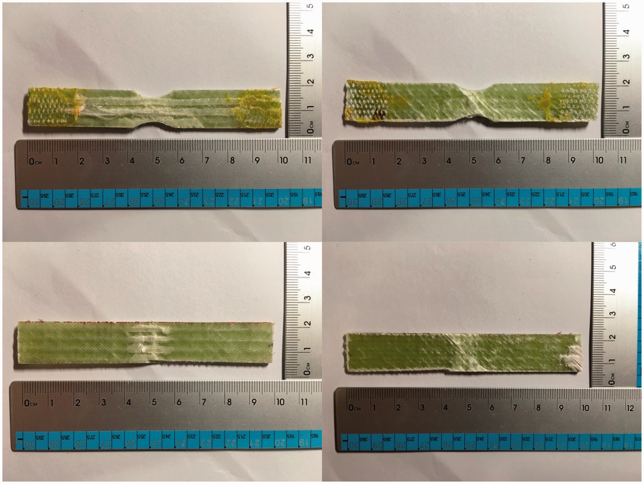
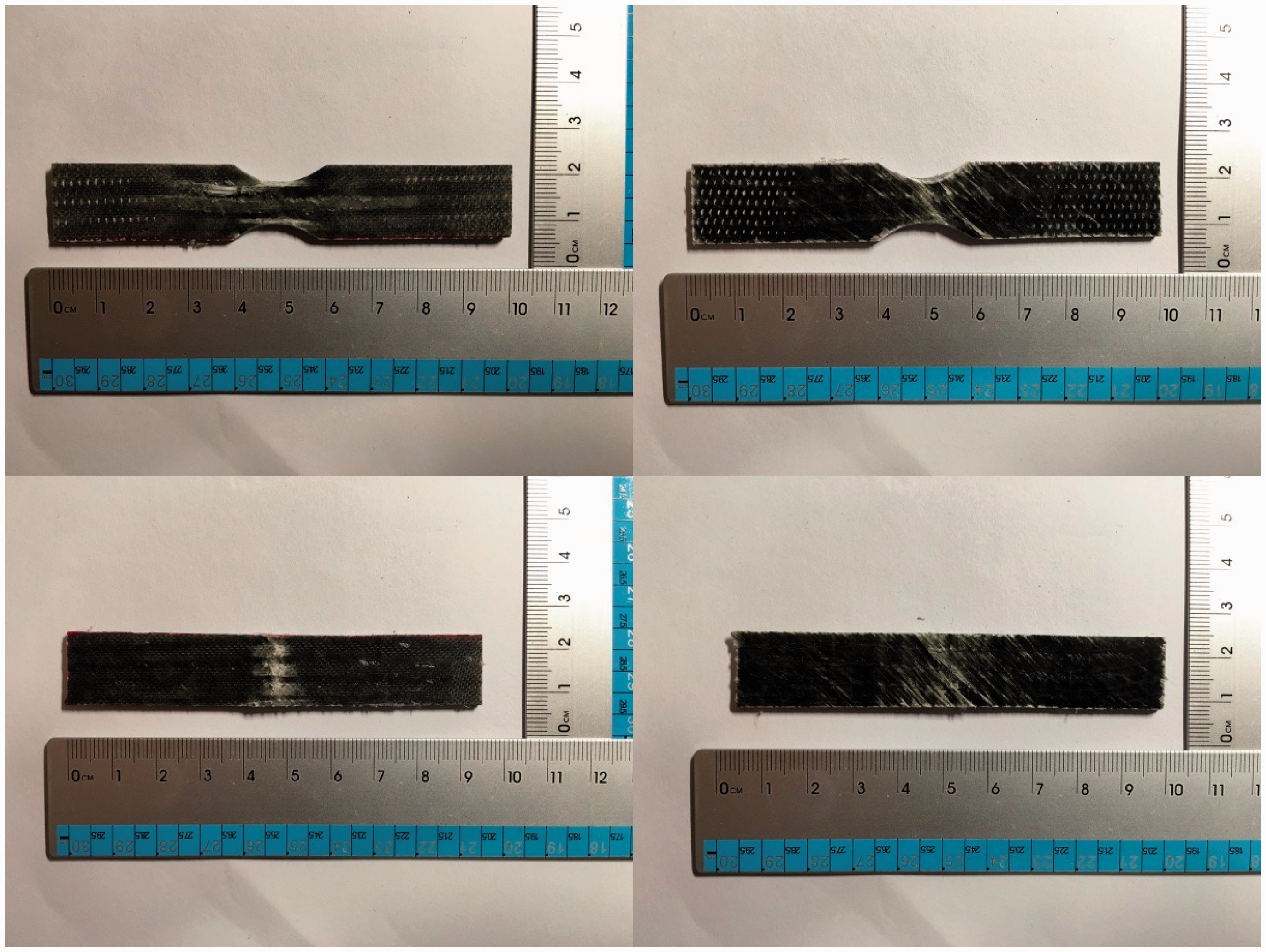
Figures 26 to 29 show different specimens after tensile and bending test. Because of the reinforcement is a multi-axial glass fiber fabric, fibers are under different stress forms in different directions. Each layer of the glass fibers damaged in different forms. The fiber breaks and it’s pulled out from the glass bundle along the stretching direction. The movement of the fiber is characterized by a slip between the fibers and this movement differs from each of the four composite but under the same applied load. The white part of the specimens is the relative motion area of the fiber and resin. Based on the analysis of the tensile data, specimens with little powder waste bears larger load than the specimens with higher addition proportion. The composite’s deformation is similarly in line with the tensile test results. Damage area of the specimens with little powder waste is also greater than the specimens with higher addition proportion on both sides. Slippage between the fiber and the resin happens on the front side of the composites, but if the break doesn't occur on the back side, then the slippage between the fibers and resin is not obvious. The fracture occurs under the action of the shearing force.
Specimens after tensile and bending tests (5 wt. %).
The main type of failure of the composites which occurred in the three point bending load test includes fiber tensile failure, surface damage, internal shear failure and many others. Figures 26 to 29 show different specimens after bending testing. Because of the multi-axial glass fiber fabric, the failure is similar to the tensile testing results. The color of the damage area is also white. During the bending test, the upper layer of the composite was under pressure, and the glass fiber under the upper layer bears the extrusion force, the extrusion force was along the fiber axis. The glass fiber of other layers slips slightly, but the fibers in the middle do not move making the middle area bears the main load. The failure of the composites on the back side is similar to the tensile tests. With respect to the four kinds of specimens with powder waste, the more the proportion of powder waste increase, the smaller the damage area within the composites.
It can be seen that composites were not completely broken apart and such characteristic is helpful in daily life. There is still a residual strength, which can still bear some load. The incomplete damage of the composites can provide protection.
Conclusions
Based on this research, the following conclusions can be drawn:
The addition of powder waste improves the mechanical properties, especially the tensile and bending properties, but this improvement must be in a certain addition proportion. With regards to the TGA test, adding powder waste to the new composites will reduce its thermal stability, but the thermal decomposition happens in a higher temperature. The addition of powder waste to the newly prepared composites contributes a slightly increase of the density. However, powder waste provides some effects on the composites. The lesser the powder added, the greater the damage area within the composites. Fires in different layers damage in different forms.
Finally, adding powder waste into the process for the preparations of new composites is possible, it can improve some characteristics. This research also realized the recycling of the obsolete composites.
Footnotes
Declaration of Conflicting Interests
The author(s) declared no potential conflicts of interest with respect to the research, authorship, and/or publication of this article.
Funding
The author(s) disclosed receipt of the following financial support for the research, authorship, and/or publication of this article: The authors acknowledge the financial support from the National Science Foundation of China (No. 11302085), the Fundamental Research Funds for the Central Universities (No. JUSRP 51625B and JUSRP51404A) and the China Postdoctoral Science Foundation(2016M591767).