
Abstract
In practice, the coated fabric is available in many shapes and sizes, not just rectangle and plane. In order to increase the shape-shifting abilities of coated fabrics, polyurethane-coated multi-axial warp-knitted fabric (PU-CMWKF) is developed. In this paper, the tensile characteristics of PU-CMWKF were investigated. Five groups of tensile experiments, with off-axial angles of 0°, 22°, 45°, 67.5°, and 90°, were conducted under constant velocity. The failure mechanism was explored by analyzing the damaged specimens. Additionally, the deformation behavior of PU-CMWKF in three regions was investigated by utilizing the digital image correlation (DIC) system, and an orthogonal anisotropic model was used to predict the modulus and Poisson’s ratio of 22.5° and 67.5°. Research results showed that the apparent modulus of PU-CMWKF strongly depended on the cut of directions. And the failure mechanism under in-plane direction loading suggests that tensile and shear failure act together. The analytical model is validated along five directions in the representation of elastic constant under corresponding small strain.
Introduction
Fiber-reinforced composite materials, with high specific strength and stiffness, are widely used in the aerospace industry, boat manufacture, architectural engineering, etc. [1–3]. To utilize such kinds of materials effectively, researchers have placed considerable importance on textile structural composites. Zheng et al. [4,5] have focused on the mechanical behaviors and structures of woven fabrics, such as testing the tensile feature under uni- and bi-axial loads [6]. In addition, mathematical models were constituted to predict the anisotropic tensile behaviors of the coated polyester woven fabrics [4,7]. Also, the important engineering parameters such as Poisson’s ratio and elastic modulus of the coated fabrics were measured. Zhou et al. [8] studied elastic modulus and Poisson’s ratio of knitted fabrics by uniaxial tensile test and obtained the elastic modulus by using linear regression. Sun et al. [9] developed a mechanical model to calculate Poisson’s ratio of the woven fabric. Penava et al. [10] analyzed the elastic constants and theoretically calculated elastic constants that had a good agreement with the experiment results. For the multi-axial warp-knitted fabrics (MWKF), the following papers are found to be useful to discuss the fabric properties, such as the comparison analysis about the mechanical properties with different polymer-coated membranes or different inserted yarns [11–13] and also the manufacture and structure investigations [14,15]. Zhou et al. [16] showed that the MWK structure with double loop pillar stitch was better than the common tricot stitch. Gao et al. [17,18] studied the properties and meso-scale mechanism of MWK from different architectures, and found that the tear properties were dependent on the structures strongly. Kong et al. [19] studied tensile extension properties and deformation mechanics on the effect of different stitching conditions. Rong et al. [20] investigated the effect of strain rate on the tensile properties and the failure models under different strain rates. Hu et al. [21] built a uniaxial tensile model for calculating the tensile modulus in any direction. Du et al. [22] developed a geometric model with the minor modification of the MWKF, which can also analyze the MWK system with six or more layers of insert yarns. Kang and Kim [23] studied the energy-absorption under impact loading.
In order to have a good vision on the strain deformation of the material during the tensile progress, the digital image correlation method (DIC) was utilized. Zhao et al. [24] thought that DIC was easy to adapt the environment and had a wide range of application. Pan et al. [25] studied on the DIC for deformation measurement, and several basic questions were solved. Kraft et al. [26] studied the orthotropic elastic constants of a micronic woven wire mesh via DIC; the DIC was used to measure the strain of the material. Pinto et al. [27] used the DIC to get the strain field and an analysis of the strain was studied in this paper.
Current research on the coated fabric and its properties, focusing on the structure of woven, the mechanical properties of MWK specifically for the study, are few. In this paper, the mechanical characterization of PU-CMWKF through a group of basic tensile experiments is revealed. Furthermore, the strain–stress curves, damaged mechanism, elastic modulus, and Poisson' ratio are explored. Besides these, the modified model, which is not symmetrical absolutely, is also discussed to express the relationship of the elastic constants.
Experimental
Materials and specimens
The material discussed in this paper is polyurethane-coating MWKF. The reinforced structure, MWKF, is shown in Figure 1(a). Apparently, the reinforced yarns are inserted in four directions. And the yarns in different directions are not interlaced with each other, but only bound by stitching yarn on the pattern of tricot. The inserted order is warp yarns (90°), yarns in −45° direction, the weft yarns (0°), and yarns in 45° direction. The cross section of the fabric is shown in Figure 1(b). The parameters of MWKF structure are listed in Table 1. The average thickness of the PU-CMWKF is 1.38 mm and the area density is 1420 g/m2.
(a) The schematic of MWKF. (b) The cross section of MWKF. Structural parameters of the MWKF.

PU-CMWKF is illustrated in Figure 2(a). Specimens were cut in five in-plane directions, i.e., 0°, 22.5°, 45°, 67.5°, and 90° with the weft direction as datum direction (0°) for uniaxial tensile experiments. Directions 0°, 45°, and 90° are parallel to the fiber directions, and 22.5° and 67.5° are the biggest angle that departs from fiber directions. The specimens were cut into 200 mm × 50 mm in size, and the gauge length was 100 mm in the uniaxial tensile test as shown in Figure 2(b).
(a) The external view of PU-CMWKF. (b) The dimensions of the specimens.
Uniaxial tensile test
The uniaxial tensile tests were carried out on the basis of ISO13934.1 at 1KN Reger6100 universal test machine, and the constant loading speed was 100 mm/min, corresponding to the nominal strain rate of 0.0278 s−1. In order to obtain the strain more than 400%, the stretch should not be stopped. For each direction, five tensile tests were performed successfully to obtain the average of apparent modulus, failure stress, failure strain, and Poisson’s ratio.
DIC systems were used to measure the deformation field and to estimate Poisson’s ratio of the material. Figure 3(a) shows the photograph and schematic of the experimental set-up. One set of DIC system includes two cameras which were used to capture the three-dimensional deformation field on the surface of the specimen. The front surface of the specimen was painted with Black-White marks (Figure 3b), which was used to obtain the coordinates of the specimens. Five photos were taken every second. The deformation of the material was computed by the commercial DIC software (included in the XJTUDIC system).
(a) The schematic of the experimental set-up. (b) The front surface of specimen.
Results and discussion
Tensile properties of PU-CMWKF
Figure 4 illustrates the strain–stress curves of five-direction representativeness of the specimens. It is noticed that the elongation of each specimen is fairly excellent which were more than 400%, and the end of the tensile test is due to the limit size of the tensile equipment instead of the breakage of the specimens.
The strain–stress curves of representativeness of the specimens.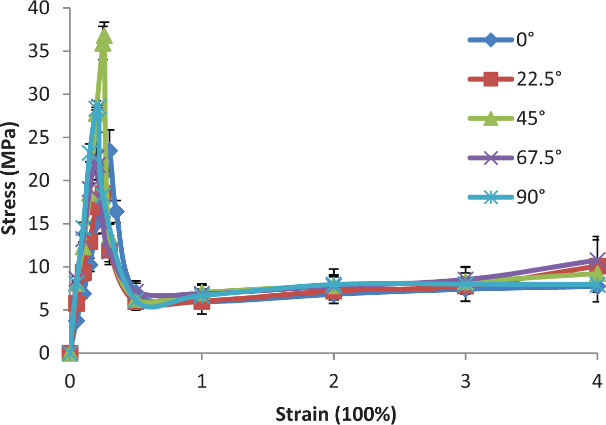
What’s more, to compare the stress after the elongation more than 100% which remained around 5 MPa, the yarns in the PU-CMWKF had been fractured at this moment. Thus, it is demonstrated that the PU-membrane exhibits excellent elongation and ductility.
From the obtained strain–stress curves (see Figure 5), the part before ultimate strain of the uniaxial tension tests, it can be noticed that the beginning parts of the curves vary from specimen to specimen because it is strongly affected by the directions.
Stress–strain curves with increase of stress.
The maximum stress and corresponding strain–stress (MPa) (%).

Failure mechanism
Figure 6(a) shows configuration of the failure 0° specimen. It can be observed that the yarns at the edge of the specimen were curly for looping, and the edge of the specimen was separated, as shown in Figure 6(b). These phenomena can be observed in all specimens. It reveals that some yarns in the specimen were drawn out from the PU-CMWKF without breaking and the two membranes were separate. Hence, it can be deduced that the interface shear debonding took place under tensile loading.
Tensile failure photograph of PU-CMWKF along direction 0° broken fiber.
As shown in Figure 6(c), the specimen was tore off, in order to have a good view of the reinforced fiber inserted in the specimen. It can be observed that the yarns were fractured, and the yarns gathered together at the side of the specimen. Thus, it can be deduced that the failure happened under tensile loading with the breakage of the fibers and the fiber cohesive failure. To compare Figures 6(c) and 2 (a) (the fabric without stretch), the fibers between 45°and −45° were rotated, which could be explained by the shear failure that happened in the tensile process.
Apparent modulus
Figure 7 shows the strain–tress curve of the 0° direction specimen within 80% of the ultimate stress. It is not exactly linear apparently. But all the R2 values obtained from the linear regression curves are completely higher than 0.95, indicating that it is reasonable to make a liner assumption. Hence, the elastic modulus between 0% and 80% of the ultimate force of this material can be obtained as in Figure 4.
The elastic modulus within 80% of the ultimate stress at the 0° direction specimen.
However, it is easy to find from Figure 5 that there was an obvious turning point in strain–stress curve, except the 0° case. In order to calculate a more accurate initial modulus, double lines (Figure 8) are utilized in this paper. The turning point which has the smallest error is obtained by the post-processing programs. And the elastic modulus values obtained from the first phase were used in this paper as in Table 3.
Double lines used to calculate the elastic modulus.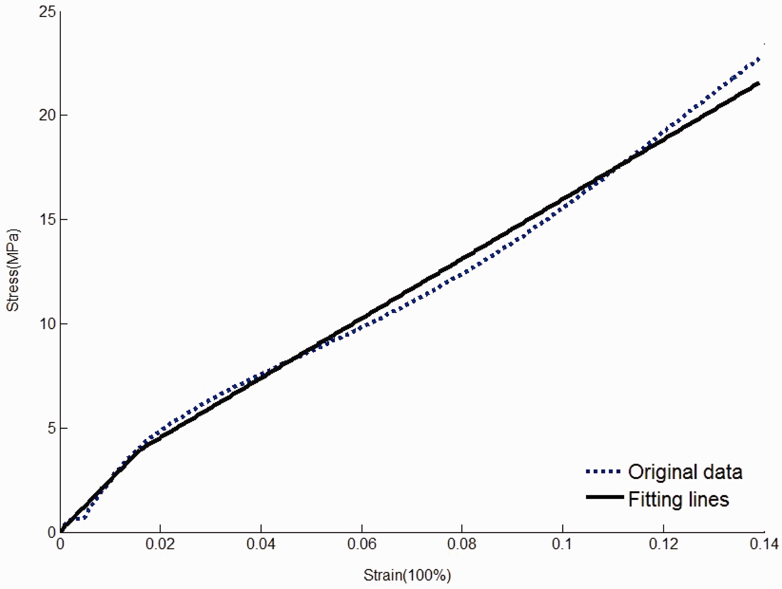
The initial modulus of specimens cut in 45°, 67.5°, and 90° directions is relatively approachable, which is also higher than that of other two, and 0° specimen is the smallest one. Also it can be seen apparently that the maximum stress of 45° specimen is higher than that of those in other directions. It can be found easily that the more the cutting direction closes to 67.5° direction, the greater initial modulus will become.
Estimation of Poisson’s ratio
Poisson’s ratio is one of the most important mechanical properties of the material. Although different testing methods have been used [25,27], the most commonly used one is the DIC technology, which is a more precise method to record the deformation of materials. In this paper, Poisson’s ratio of the flexible material is calculated by this method. However, it is difficult to ensure every painted point in the specimen under perfect uniaxial stress state because of the effects of material heterogeneity and boundary condition. Therefore, several approximate methods are proposed to estimate the “apparent” Poisson’s ratio of materials as follows.
At the beginning, the way used to calculate Poisson’s ratio by means of the transverse strain and axial strain in the center of the specimen is shown in Figure 9(a), it is a standard picture which is plotted by the DIC system marked with about 4800 datum points.
(a) The standard picture plotted by DIC system marked with datum points. (b) The result of Epsilon Y = 1% calculated by the DIC system.
However, as shown in Figure 9(b), the result of Epsilon Y = 1% calculated by the DIC system indicated that the deformation of the specimens are not homogenous, as the consequence, Poisson’s ratio obtained by this way is not be able to reflect the real strain change of the whole specimen. In this case, more lines are taken into consideration. Thus, after calculating by the DIC system, the coordinates of all the points at every tensile state can be obtained, and the corresponding points at the edge of the specimen were used to calculate the strains, the average of transverse strains and axial strains are then used to obtain Poisson’s ratio in the following methods.
Values of the elastic modulus in five directions (MPa).

Poisson’s ratios obtained from the whole specimen.

However, the second method considers the boundary effect which requires the selection of a shrunken region far away from the fixture. Figure 10 illustrates the region of ABCD graphically, the length of axial region is set as the same as that of transverse region which is chosen up to maximum length. Also, the calculating method is the same as the method 2 and the result is shown in Table 5 and Figure 11.
Square region of ABCD choose for calculating Poisson’s ratio. (a) Strain contours of y (Epsilon Y = 1%). (b) Strain contours of x (Epsilon Y = 1%). (c) Strain contours of y (Epsilon Y = 2%). (d) Strain contours of x (Epsilon Y = 2%). Poisson’s ratios result of the square region.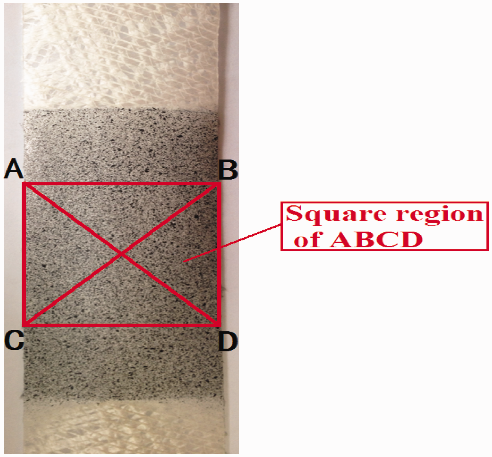


The last method used in this paper calculates the average strains only by using the central part of the specimen. Figure 12 illustrates the region (EFGH) selected to estimate Poisson’s ratio, and the result is shown in Table 6 and Figure 13.
Region (EFGH) chosen for calculating Poisson’s ratio. (a) Strain contours of y (Epsilon Y = 1%). (b) Strain contours of x (Epsilon Y = 1%). (c) Strain contours of y (Epsilon Y = 2%). (d) Strain contours of x (Epsilon Y = 2%). Poisson’s ratios’ result of EFGH region.


The analysis model
In order to further investigate the PU-CMWKF, the material is treated as a thin orthotropic sheet. And the orthotropic and elastic materials can be described by the following off-axial constitutive relationship [4,7]
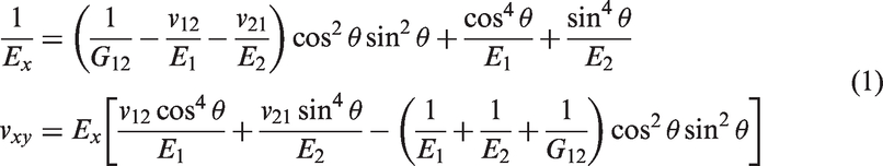
In the equations, the suffixes 1 and 2 represent the principal directions of the material; suffixes x and y correspond to the loading directions of the material, E, v, G, and θ denote the Elastic modulus, Poisson’s ratios, shear modulus, and the off-axial angle in relation to the principal direction 1, respectively.
Let, E3 = 
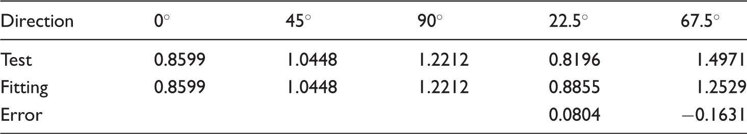
The predicted elastic modulus obtained by the whole specimen.

The predicted results obtained by the whole specimen.

The predicted results obtained by the square region of the specimen.

The predicted results obtained by the EFGH region of the specimen.
To compare the predicted errors in the direction of 22.5°, it is obvious that the errors in the whole region and the square region of the specimen are similar and smaller than that of the region EFGH. It indicates that a more accurate predicted error in the direction of 22.5° can be obtained by choosing the transversal area with a length as long as possible.
In the direction of 67.5°, the predicted errors of the EFGH region are the smallest and most accurate; however, the predicted errors in the square region are the largest. There are no yarns run through the area according to the area proportion and, therefore, it is more accurate to predict Poisson's ratio of 67.5° when the axial length was long.
However, generally, the investigation of the predicted results of Poisson’s ratios reveals that the PU-CMWKF material fits the test data very well with the errors all <20%, and by comparing the predicted results, it suggests a more effective way by using the square region to calculate Poisson's ratios of this material in off-axial directions.
Conclusion
This type of PU-CMWKF is commonly used in construction, transportation, and other fields. It is easily affected by multiple forces in different directions in the process of use that would affect the security and service life. In this paper, the tensile property of the PU-CMWKF is tested at different directions. By comparing the strain–stress curves obtained by experiment, it reveals that the initial modulus is different among specimens in different directions. The more the closer to 67.5°, the higher the initial modulus is. In other words, the PU-CMWKF has a good strengthening effect when it is perpendicular or skewed to the direction. It can adapt the individuation and diversification of actual demand. Moreover, the characteristic of great elongation of the PU-CMWKF is particularly significant, more than 400%.
Three main states result in the failure of this material under tensile load: interface shear debonding, the fiber cohesive failure, and the breakage of the fibers. All these specimens are damaged under tension together shear load.
Different methods are selected to estimate Poisson’s ratio of this material. It can be observed that, there is an accurate predicted result in the direction of 22.5° by choosing the region of transverse as large as possible. Also, in the region of EFGH, the predicted results of 67.5° are the most accurate one. Generally, all the methods used to calculate Poisson’s ratio of the material are relatively accurate, and the region of square region used to calculate Poisson's ratio is more effective in both the directions.
From the predicted results obtained by orthogonal anisotropic model, the errors of Elastic modulus and Poisson’s ratio are less than 23.62%. Thus, the PU-CMWKF is orthotropic material when strain is less than 2%.
Footnotes
Declaration of Conflicting Interests
The author(s) declared no potential conflicts of interest with respect to the research, authorship, and/or publication of this article.
Funding
The author(s) disclosed receipt of the following financial support for the research, authorship, and/or publication of this article: The authors of this paper gratefully acknowledge the support of National Natural Science Foundation of China (NSFC 11472077), Shanghai Natural Science Foundation (13ZR1400500), and Fundamental Research Funds for the Central Universities (2232015D3-0, XDJK2013C132, and XDJK2014C127).