
Abstract
In this study, a novel approach and the related equipment of coaxial electrospinning have been developed to fabricate a new ultrafine polysulfone amide/polyurethane coaxial fibers at nanoscale, with the polysulfone amide as the core and the polyurethane as the shell of the blended fibers. As the co-spinneret has effects on the structure and properties of the spun fiber, three types of co-spinnerets with different diameters were designed to investigate its effects on the fabricated fibers in this research. Three series of polysulfone amide/polyurethane coaxial fibers were spun using the self-developed coaxial electrospinning equipment, and these fibers were characterized systematically using scanning electron microscope, transmission electron microscope, X-ray diffraction, differential scanning calorimeter and thermogravimetric. High-speed photography was used to digitalize the image of the tailor cone and jet motion of polymer fluid during the spinning process, which provides a detailed description of the electrospinning for the further theoretical analysis. The three-dimensional electric field simulation was also carried out to model the differences of electric field. Our experimental results show that the mechanical and thermal properties of the core–shell fibers fabricated in this research have been improved in the comparison with the fibers spun using the conventional single-needle electrospinning method. The composite fibers have the core–shell structure, so that it can combine the excellent thermal properties of the polysulfone amide and the excellent mechanical properties of the polyurethane. The newly developed polysulfone amide/polyurethane fiber could be used in the field of industrial textiles; it has the potential applications for the development of high-performance apparels in the future.
Introduction
Co-electrospinning is one of the new expanded methods based on the previously known electrospinning [1,2], which can fabricate the core–shell fibers at the nanoscale using the nanotechnology. To develop new functional nanofibers, some researchers have presented the concept of co-electrospinning (or coaxial electrospinning) to produce the core–shell composite nanofibers [3–6]. It was reported that the polymer solutions could be supplied from a spinneret consisting of two coaxial capillaries. A core–shell droplet emerges and spurts from the spinneret, and when the electric field is sufficiently strong, the jet could be sprayed fast away from its tip [7]. The sprayed jet could be solidified after the solvent existing inside the jet evaporates eventually, and then, the as-spun fibers with the core–shell structure could be deposited on the electrode receivers [8].
In recent years, many researchers have investigated the optimized co-electrospinning methods and the related equipment, such as increasing the numbers of spinnerets to improve the distribution performance of the electric field [9,10], or designing a new flat core–shell spinneret to expand the distribution of the electric field [11]. Zhou et al. [12] reported a new needleless emulsion electrospinning method for scale-up fabrication of ultrathin core–shell polyacrylonitrile (PAN)/isophoronediisocyanate (IPDI) fibers, which can be incorporated at the interfaces of polymer composites for interfacial toughening and self-repairing due to polymerization of IPDI triggered by environmental moisture. Zheng et al. [13] designed a new multihole spinneret with equilateral hexagon hole array to meet a high-production requirement and high quality of nanofibers. Wu et al. [14] developed an approach to the scale-up of co-electrospinning via a flat core–shell structure spinneret which has a flat surface involves shell holes and core needles to fabricate composite nanofibers with special morphologies.
Meanwhile, some scientists have developed the new functional materials at the nanoscale by using these co-electrospinning methods. Lin et al. [15] reported a polystyrene/polyurethane (PU) fiber as a sorbent for oil soak-up via coaxial electrospinning. They showed that the resultant composite PS-TPU fibers orientated randomly in a form of non-woven mats with nanoscale structure. Zhu et al. [16] synthesized p-CuO/n-TiO2 composite nanofibers using side-by-side electrospinning combined with sol–gel process. They found that the configuration of spinneret had obvious effect on the preparation efficiency of the composite fibers.
For obtaining multifunctional fibers, the location and spinning direction of the spinnerets could be changed to prepare bi-component fibers. Tijing et al. [17] used side-by-side angled two-nozzle electrospinning to improve the quality of the electrospun nanofibers. Others developed special functional fibers by the blending of different polymer materials for complementary performances. For example, Chen et al. [18] provided an effective method of making nanoscale fibers via combining flexible thermoplastic elastomer polyurethane (TPU) component and a rigid thermoplastic component using coaxial co-electrospinning systems. Kessick and Tepper [19] reported the formation of core–shell structures from a composite of one conducting polymer poly(aniline sulfonic acid) and one non-conducting polymer poly(ethylene oxide) by conventional electrospinning from a two-component solution.
Although many researches have been done for the development of core–shell nanofibers, very few works have been reported to spin the composite fibers containing the polysulfone amide (PSA) and PU. It is valuable to present a new method and the related spinning system which can be used to develop the PSA and PU core–shell nanofibers. It is well known that PSA fiber has excellent heat resistance, flame retardant, thermal stability, etc., so that it can be applied to develop those protective products used in aerospace, high-temperature environments and civil fields to satisfy the flame retardant requirements. PU consists of the hard and soft segments. The hard segments of the PU can improve its mechanical properties due to a relatively high-transition temperature, whereas the soft segments of the PU are with a better elasticity. Also, it is reported that PU has good blood compatibility, which causes it to be of considerable value in medical devices [20]. However, the thermal stability of PU is not as good as the PSA, while the mechanical properties of the PSA are not good enough for the designing of functional textile in some cases. Therefore, it is possible to combine these two polymers to spin the composite fiber, which endows both advantages of these two kinds of polymer.
In this work, the composite core–shell nanofibers with an elastomeric component (PU) and a rigid component (PSA) were prepared by co-electrospinning technique. As PU has perfect mechanical properties, it can be selected as the core component of the composite yarn; PSA has good flame retardant property, so it can be selected as the shell component to improve the thermal stability of the composite yarn. Through the combination of these two polymers, it is feasible to improve the overall performance of the core–shell composite fibers. Meanwhile, three-dimensional (3D) electric field simulation is used to investigate the formation of the core–shell structures, three sets of co-spinnerets are designed and fabricated to do the comparison experiments and three kinds of electric field distribution with different needles’ shape have been studied systematically.
Experiments and simulation
Material preparation
The PSA was used as spinning solution with the intrinsic viscosity of 2.3 dL/g, and N,N,-dimethylacetamide (DMAc) was selected as dissolvent in this study. The two of them were supplied by Shanghai Tanlon Fiber Co., Ltd., China. PU (5526) was supplied by DUPONT, USA. All of these materials were used without further purification.
A certain amount of PSA was dissolved in the DMAc solution using ultrasonic vibration for 60 min at 60℃. PU solution was prepared by dissolving the PU chips in solvents of DMAc, and the mixture solution was stirred for 4 h at the room temperature. In our experiments, the solid concentration of the PSA solution was set to be 10%, the PU solution was 20% to satisfy the viscosity requirement for the electrospinning process and the spinning was performed at 20℃ and 40%–60% relative humidity (RH) in air.
Experimental setup
The schematic of the co-electrospinning system is shown in Figure 1. Three core–shell spinnerets with different diameters were made by positioning the core needle inside the center of a coaxial spinneret, as depicted in Figure 2. As the minimum core–shell spinneret, the core needle was a blunt-type stainless steel needle with inner and outer diameters of 0.34 and 0.64 mm, respectively. The shell needle was also stainless steel with inner diameter of 1.25 mm. The middle core–shell spinneret has core needle with inner diameter of 0.51 and outer diameter of 0.82 and shell needle with inner diameter of 1.36 mm. The maximum core–shell spinneret was composed of core needle which has inner and outer diameters of 0.75 and 1.00 mm and shell needle with inner diameter of 1.55 mm. The solutions for the core and shell materials were separately injected into the spinneret via corresponding syringes and pumps. A high-voltage supply was applied to the spinneret and the metal collector used in this experiment was flat-shaped. The experimental parameters of the coaxial electrostatic spinning process were set as follows: (a) the extrusion speed was set to be 0.0001 mm/s, (b) the voltage and distance were 25 kV and 15 cm and (c) all spinning process was under 45℃.
Schematic of the self-designed co-electrospinning system. Coaxial spinnerets (minimum sized on the left and maximum sized on the right).

Characterization
The surface morphology of the prepared core–shell fibers were investigated using a scanning electron microscope (SEM) (S-3400N, Japan) after the process of gold coating (coating time is 60 s). The internal morphology of the core–shell fibers was studied using transmission electron microscope (TEM) (JEM-2100, JEOL, Japan). The statistical calculation of the fiber diameter from the SEM images was done using Image-Pro Plus software (Media Cybernetics Co., USA). The mechanical behavior of electrospun core–shell fibers was investigated with a single-fiber testing machine (YG006) under a crosshead speed of 20 mm/min at room temperature. The crystalline structure of the fibers was characterized using the X-ray diffraction (XRD) (k780 FirmV_06). The thermal properties of coaxial fibers were determined using the thermogravimetric (TG) analyzer and differential scanning calorimeter (DSC).
Imaging of the jet path
A high-speed camera (HG-100 K, Redlake Inc., San Diego, USA) equipped with a Nikon 24-85 mm, f 2.8 zoom lens was employed to digitalize the image sequences of the jet motion during the co-electrospinning process. The used camera has the capability of recording images at a frame rate up to 100,000 frames per second (f/s). The light source used in our experiments was two 2500 W fluorescent lamps. A Nikon digital camera (Nikon Inc., Japan) equipped with a Nikon 24-85 mm, f 2.8 zoom lens was also employed in the experiment.
Electric field simulation
The 3D electric fields were simulated and analyzed by COMSOL Multiphysics (COMSOL Inc, Swedish). The electric field intensities were calculated by COMSOL software. Before the calculation, the physical geometries of the co-electrospinning setups (e.g., electrode, spinneret and collector) and polymer solutions were established according to the practical dimensions, locations and relative permittivity used in our experiments.
Results and discussion
Jet path
Figure 3 shows the composite droplets formed at the tip of three different core–shell spinnerets under the conditions of 15 cm working distance and 25-kV applied voltage separately. The PU-core solution was color-dyed to enhance the contrast of the imaging object and the background. The red shell solution and white core solution can be identified clearly from the image.
Composite droplet formed at the tip of the core–shell spinneret. (a) Minimum core–shell spinneret. (b) Middle core–shell spinneret. (c) Maximum core–shell spinneret.
Figure 4 shows that the shape of the droplets can be changed with the increasing size of spinnerets. The magnified image of spinneret is illustrated in Figure 4. The jet processing of the minimum spinneret is shown in Figure 4(a). At the beginning, the range of voltage is between 5 and 10 kV which is too low to draw the droplet to form the fiber. Figure 4(a-1) shows that the shape of the composite droplets looks like half ellipses. It is observed that droplets are becoming more and more acute with the increasing of the voltage as illustrated in the three pictures. When the voltage is up to 25 kV, Taylor cone is so sharp and stable that the fibers which are being stretched can be identified clearly. The forming of the droplets and the spraying of the jet in Figure 4(a) are the same as the forming process of Taylor cone in Figure 4(b) and (c). The yellow lines in Figure (a-4), (b-4) and (c-4) denote the angle of jet spraying, which becomes larger with the increasing size of the needle diameter. The distribution of electric field is associated and affected by the diameter of needles. The jet path in the stable stage of the spinning process is similar to the jet motion in a single-fluid electrospinning process [21]; however, it is different with the electrospun processing of off-centered core–shell spinneret which has many coils at the beginning of jet spraying [19].
The forming process of the Taylor cone when voltage increasing from 0 to 25 kV. (a) The minimum core–shell spinneret. (b) The middle core–shell spinneret. (c) The maximum core–shell spinneret.
Electric field distribution
The 3D electric fields formed by the three co-electrospinning system with different needles were simulated by the COMSOL Metaphysics® Finite Elemental Analysis software. The simulations were under the conditions of 15-cm working distance and 25-kV applied voltage, which have been used successfully in our previous experiments for a stable spinning process. The lines of simulated electric fields formed by the three types of spinneret can be used to describe the distribution of the electric field running for the electrospinning and make comparison with the experimental observation as shown in image a1, b1 and c1. The direction and length of the arrow represent the orientation of the electric field lines and the strength of its intensity, respectively. It seems that the electric field lines generated in the minimum sized needle are more concentrated around the central line of the spinneret, while the electric field lines are scattered and distributed outwards the central line of the spinneret for the maximum sized needle, which corresponds to the distribution angle of jet spraying. That means the distribution of the electric field determines the size and range of the jet whipping. It is obvious that length of arrow is elongated with the increase of needle diameter, which can be used to describe the change of its intensity.
Other images are top view and main view of the cross-sectional surface of electric field distribution for different co-spinnerets. The electric field distribution of these images is similar with each other, belonging to an inhomogeneous electric field with an extremely high electric field concentrated in the surrounding area of the needle. The points of A, B and C in Figure 5 are in the same position, respectively; however, they have various electric field intensities with different values. The calculated data demonstrate that the electric field intensity increases as the increasing size of co-needles, as shown in a3, b3 and c3.
Simulation of electric field of three co-spinnerets. (a) Series are the minimum spinnret. (b) Series are the middle spinneret. (c) Series are the maximum spinneret. a1, b1 and c1 are simulation of electric field lines. a2, b2 and c2 are simulation of top view of electric field distribution. a3, b3 and c3 are simulation of main view of electric field distribution.
Morphology of PSA/PU composite fibers
SEM analysis
The SEM image of the electrospun PSA/PU fibers spun using the co-electrospinning system is shown as the left image in Figure 6. The distributions of fiber diameter at various needles are shown as the right chart in Figure 6. The fibers were prepared by electrospinning 12 wt% PSA as shell component and 20 wt% PU as core component. The processing conditions were set to be 15-cm working distance and 25-kV applied voltage. The range of fiber diameters varies from 100 to 300 nm. From the SEM images, it is found that the spinnerets with larger diameters can be used to spin more helical nanofibers; the reason behind this is that it may be caused by a wide range of spraying and whipping. It is well known that the uniformity of the core–shell structures is one of the most important factors for the application of core–shell nanofibers. The uniformity of fibers in this experiment is in the desired range because proper crimp can increase the fiber strength which will be discussed next. Wu et al. [22] mentioned that helical structures of the nanofibers are expected to contribute better resiliency and flexibility of the fiber mechanical properties. They observed that helical conformation can be found in biological systems such as plant tendril and the electrospun helical nanofiber resemble the tendrils in shapes. Therefore, compared with the experiment made by Wu, the fiber curl in this discussion is acceptable, which indicates that it is better to choose smaller co-needles to spin the smooth and superfine fibers; however, the larger co-spinnerets should be used to spin the fibers with better mechanical properties.
The SEM image (left) and diameter distributions (right) of fiber at various needles. (a) The minimum core–shell spinneret. (b) The medium core–shell spinneret. (c) The maximum core–shell spinneret.
TEM analysis
The TEM images in Figure 7 demonstrate the impact of different diameters on the coaxiality of PSA/PU fiber. Under the same spinning condition, the surface of overall fibers appears to be very smooth and straight. However, there is a huge discrepancy inside these fibers as illustrated in the TEM images. The minimum sized coaxial spinnerets can be used to spin the fiber with superfine structure; however, the boundary between the core and shell part is not clear, as depicted in Figure 7(a). However, Figure 7(b) and (c) illustrates that the core fiber produced from the bigger sized spinneret is more clarity. Based on the simulation results, higher electric field can be generated by the bigger needle, the fiber is fully stretched due to the strong electric force. The mechanical behavior of PSA and PU droplets seems to be different during the spinning process; therefore, the overall morphology of the core–shell fibers should be investigated in the consideration of both the internal and external structure.
The TEM images of fibers. (a) The minimum core–shell spinneret. (b) The middle core–shell spinneret, (c) The maximum core–shell spinneret.
XRD analysis
XRD is used to investigate the phase structures of the composite nanofibers. For comparison, the XRD data of the pure PSA and PU were also measured in our experiment. Figure 8 shows the XRD patterns of pristine and composite PSA/PU nanofibers. The XRD pattern of pristine PSA nanofibers demonstrates a broad peak at 24° due to the amorphous nature, and the PU is at 21°. The core–shell fibers were spun using the co-needle spinning system, the PU was blended with the PSA to form the core–shell structure, and therefore, the diffraction peak of the composite fiber is shift to the left compared with the diffraction peak of pure PSA as that the peak of PU is less than PSA. The intensity of the diffraction patterns was increased with increasing diameter of spinnerets as line(4), line(3) and line(2) in orders. However, it is observed that the intensity of composite nanofibers is greater than PSA but less than PU which is one of factors to influence mechanical properties as illustrated in Figure 8.
XRD curves of electrospun neat PU and PSA by single-nozzle and composite fibers by coaxial-nozzle.
Mechanical properties
The average tensile strength of the composite nanofibers with different spinneret is depicted in Figure 9. Meanwhile, pristine PSA and PU were also included to do the comparison with nanofibers made by coaxial electrospun. The summarized result of tensile strength and strain from five prepared fibers is shown in Table 1. The mechanical properties of the pristine PU fiber are better than the pristine PSA because the PSA fiber is a little brittle compared with PU. The PSA/PU composite fiber spun using co-electrospinning method has better tensile strength than pristine PSA but poor than PU nanofibers. With the increase of jet hole, there is a tendency that the strength of coaxial spun fibers is increasing.
Tensile strength curves of electrospun neat PU and PSA by single-nozzle and composite fibers by coaxial-nozzle. Data of mechanical properties about the electrospun neat PU and PSA by single-nozzle and composite fibers by coaxial-nozzle. PSA: polysulfone amide; PU: polyurethane. DSC curve of electrospun neat PU and PSA by single-nozzle and composite fibers by coaxial-nozzle.

In the previous paragraph, it was mentioned that fibers from bigger spinneret are more curled and twisted than the small ones and the crystallinity is greater for larger ones. These two phenomena might be the cause of this result. Moreover, Sambaer et al. [23] have studied that the larger jet diameter covers a greater area for the fibers than that of the smaller jet diameter which brought the result is that the density of fibers became greater. Therefore, the mechanical strength of the composite fiber obtained from the co-nozzle system is greater than the pristine PSA fiber obtained from the single-nozzle system. It is a good way to improve the density of PSA without damaging the PSA.
From Table 1, it can be concluded that core–shell nanofibers with a special structure produced by this new designed setup were finer than conventional PSA nanofibers prepared by single-needle electrospun in the consideration of breaking strength, breaking elongation and strain.
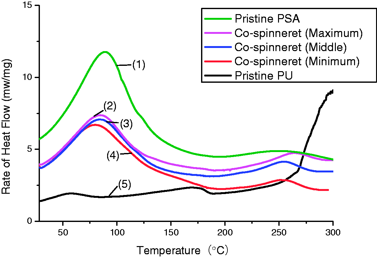
Thermal properties
DSC curve of five fibers prepared in this research has been illustrated in Figure 10. Lines (1) and (4) represent PSA and PU, respectively. Line (1) representing pristine PSA has a diffuse peak from 30℃ to 130℃ due to the evaporation of the water. The endotherm of region around 250℃ may be resulted by the volatilization of water between polymer molecules and various additives [24]. The black line (5) associated the major weight loss can be divided into three sections of heat weightlessness about PU. The endotherm around 30℃ to 75℃ corresponding to the disruption of short-range order of the hard segments induced by room temperature annealing. The region between 150℃ and 200℃ may be caused by the disruption of long-range order of hard segment. When the temperature is up to 250℃, PU reaches the temperature of the thermal decomposition.
When line (5) is compared with lines (2), (3) and (4), the curves of the core–shell fibers provided by co-electrospinning had a sudden steep which means that the addition of PSA in PU changes the behavior of thermal decomposition from 50℃ to 150℃. Meanwhile, PSA delayed the decomposition of the PU after 250℃ because PSA, which is located as the shell part outside, is able to protect the core part of PU. Wei et al. [25] mentioned the cross links are so important that can immobilize the chains to some extent. Therefore, the link between PU and PSA has the effect of decreasing the decomposition temperature.
Thermal performance analysis
Both the TG and derivative thermogravimetric (DTG) curves of PSA, PU and the PSA/PU composites are illustrated in Figure 11, respectively. From the TG curve, it can be observed that pure PU has three stages of weight loss which starts from about 260℃. The first stage is in the range of 262℃–352℃, the second phase is in the range of 360℃–460℃ and the third stage is 460℃–700℃. It can be concluded that there are two thermal decomposition peaks between 200℃ and 450℃ because the flexible PU molecule is made up of long chains (soft chain segment) and short chains (rigid chain segments) which decomposes one after another.
TG curves (left) and the DTG curves (right) of PSA and PU as well as the PSA/PU composites.
The curve of pure PSA fiber can be divided into roughly three intervals [26]. The first stage comes mainly from the volatilization of combined water between polymer molecules and various additives when room temperature is up to 100℃. The second loss may be the increasing high-polymer macromolecule chain movement rate until fracture, with small molecular substances releasing in the form of gas formation. The third is carbon stable stage (600℃–700℃). There is not much effect of weightlessness when rising temperature as a result of that most polymer materials have carbide A.
Parameters of different PSA/PU composites during the thermal decomposition.

T0: the initial decomposition temperature; d α /d t : the maximum deposition rate; Tmax (℃): the temperature at maximum rate; α: the residual mass at 700℃; PSA: polysulfone amide; PU: polyurethane.
Conclusions
The PSA/PU composite core–shell fibers fabricated from three different diameter spinnerets were characterized systematically for the development of new functional textile materials. The images of the tailor cone and jet motion of polymer fluid during the spinning process were digitalized to investigate the forming of droplets and the spraying of the jet. The 3D electric field simulation was also carried out to model the differences of electric field. The experimental results can be summarized as follows: The electric field lines are scattered outwards with the increasing of co-spinneret diameter, the field distribution angle corresponds to the angle of fiber whipping. The strength of electric field produced by larger sized spinnerets was strong than small ones. The morphology of core–shell fibers produced by small co-needle has smooth surface while with unclear solution boundaries. However, large co-needle produced more helical fibers due to wide range of whipping. The mechanical and thermal properties of the core–shell fibers fabricated can been improved in the comparison with the fibers spun using the conventional single-needle electrospinning. The core–shell structure can combine the excellent thermal properties of the PSA and the excellent mechanical properties of the PU. Compared three kind of coaxial fibers, it was found that larger fibers have better mechanical and thermal properties because of more coarse diameters and curling due to the jet whipping.
Footnotes
Declaration of Conflicting Interests
The author(s) declared no potential conflicts of interest with respect to the research, authorship and/or publication of this article.
Funding
The author(s) received no financial support for the research, authorship and/or publication of this article.