
Abstract
For decades, street lighting and electric poles are made of metal and it is vulnerable to corrosion due to the harsh weather and chemicals. To overcome such essential problems, galvanized iron is used although it adds more hard work to increase the manufacturing cost. Therefore, fiber reinforced polymer lighting pole is proposed. Fiber reinforced polymer materials possess many advantages such as corrosion resistance, high specific strength and stiffness, etc. Two-dimensional woven fabrics and three-dimensional woven fabrics preforms are used to produce composite structures. However, complex shapes cannot be manufactured as a one piece preform. Woven fabrics, whether two-dimensional or three-dimensional need to be cut into patterns to finally produce the complex shapes. These processes add more cost and time to the final composite products. In this research, innovative technique to produce a three-dimensional complex shape knitted preform using regular flat-knitting machine will be presented. Production of such shaped three-dimensional preform permits the production of one piece-shaped preform without any connection or further sewing processes. Produced knitted preform can be used for various reinforcement applications such as light and communication poles, scaffold façades, traffic sign, oars, and wind mill blades.
Keywords
Introduction
For many years, metal alloys have been used for manufacturing of lighting poles, traffic signs, and communications lines. For all these years, corrosion has been considered a major problem due to the severe effect on structure integrity. Corrosion may lead structure to collapse, which threats people lives [1]. Thus, heavy weight, high maintenance required, and corrosion of metals have opened research areas to replace metals with fiber reinforced polymer (FRP) [2]. FRP materials are known to be stronger, lighter than steel, and resistant to corrosion. These advantages have opened the door for them to replace steel and metals alloy in numerous markets and applications like military, aerospace, windmill, automotive, bridges, and constructions [3]. Thus, there is a growing increase in using FRP in construction of outdoor light poles [4].
From the design perspective, light poles consist of several parts, namely anchor base (pole base), pole shaft, supports, and brackets/arms [5]. These parts need to be assembled and welded together to form the final three-dimensional (3D) shape of the light pole. Therefore, the final shape of any light pole is considered complex.
Two-dimensional (2D) fabrics reinforced polymer has been used for decades in aircrafts, high performance vehicle, and civil infrastructure such as building, poles, bridges, and pipe lines [6–8]. Textile preforms have been used as a composite reinforcement material due to their advantages such as easy to handle, can be tailored to fit different shapes, and for their good mechanical properties [9–11]. To acquire the final shape of the light pole, stacks of 2D laminates are used to reach 3D shape and stitching may be applied to bind all stacks together [12, 13]. High cost is considered one of the main drawbacks of the laminates manufacturing and this is due to the high labor intensive in manual layup. Using a prepreg laminates adds extra cost to the composite production as the large and expensive refrigerator is needed to extend the shelf lives of the prepreg before the resin consolidates. Molding complex shapes using prepreg laminates is difficult as the prepreg and fabric plies characterized by its poor drape properties. Therefore, the final complex shape cannot be fabricated as one piece and need to be fabricated using several laminate parts that are joined together by cocuring, adhesive bonding, or mechanical fastening [14].
On the other hand, 3D orthogonal woven preform and layer interlock weave are two of the most common 3D fabric architecture, whereas all layers are integrated in three directions (X, Y, and Z) to form the final 3D structure [15]. Despite the technology development in creating 3D preform, the fabrication of 3D complex shapes using woven preforms is still difficult. This difficulty due to its inherit inflexibility, the manufacture of highly curved shapes requires the woven preform to be cut into shapes for folding, which adds more cost and hand labor. On the other hand, 3D-knitting preform presents a fabric that is characterized by its high deformability and directly fabricated with the required 3D complex shapes [16, 17]. Several attempts were conducted on weft-knitting machines to produce spacer fabric as a complex shape that can be used for composite materials [18, 19]. Knitting machine with special technical requirement was used to develop 3D spacer fabrics with four reinforcement layers [20–22].
Nevertheless, several studies were conducted on FRP poles using filament winding and pultrusion techniques, whereas these two fabrication methods are dominating the fabrication techniques of FRP poles. Behavior of scaled FRP transmission poles under cantilever loading conditions was investigated [23]. FRP light pole with 76 mm outer diameter and 6 mm wall thickness diameter was fabricated by filament winding. Linear behavior of the FRP poles was observed up to failure. Study on the flexural behavior of lightweight (FRP) poles was carried out by Slimane and Radhouane [24]. FRP poles with length ranging from 5 to 12 m were fabricated and tested under static flexural. Glass fibers with two different linear densities were used. Filament winding was used to fabricate the FRP poles. FRP poles are divided into different zones, whereas the number of layer and fiber orientation are different from one zone to another. Results indicated that the use of low linear density glass fibers could increase the ultimate load-carrying capacity up to 38% for some FRP poles.
In this paper, a state of the art of complex 3D-knitted preform production technique is presented to provide a possible solution to overcome the 2D and 3D preforms’ drawback. This technique proves the possibility of producing a complex 3D-shaped preform that contains all the light pole parts in one preform unit and no further cut into shape or tailoring are required. One piece preform with different designs and shapes such as scaffold façade, oars, and ladders can be fabricated using this technique.
Light pole
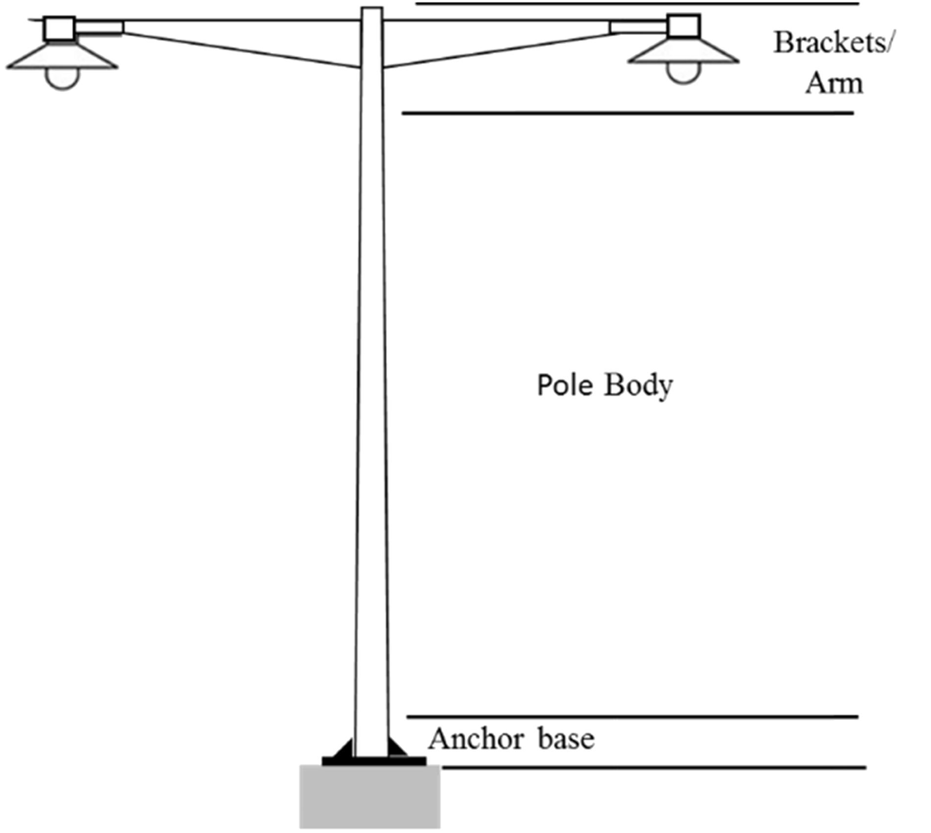
There are many different shapes and designs of outdoor light poles, although all light poles consist of three main parts, anchor base, pole shaft, and brackets/arm. These parts are shown in Figure 1.
Anchor base: which is a metal square or round in shape with slotted holes for anchor bolt. Pole Shaft: there are several designs of pole shafts such as round conical, octagonal tapered, straight square, and tubular stepped. Brackets/arm: Single or double brackets/arm are in the shape and dimension as per customers requirement. Schematic diagram of common street metal light pole. Light pole parts and welding location (indicated in red color). Concept design for light pole (2D design).
Manufacturing light poles is not an easy process, whereas each part has to be prepared first and then all parts are assembled together. Anchor base, for instance, is made of two different parts (square base with slotted holes and anchor/pole support) that are welded together (Figure 3). Pole shafts are made of steel sheet that is folded into required shape and welded longitudinally by automatic arc welding machine. Pole shaft is also welded to the anchor base and to the two rectangular supports (Figure 2). The top parts of the light pole are the brackets or arm which is the part that holds the light source. This bracket or arm made is manufactured separately and it is made of steel sheets that is folded into required shape and welded together and the final bracket or arm is welded to the pole shaft (Figure 2). Red lines in Figure 2 show the welded location for each part of the light pole and welded location of each part to the main pole shaft.


Experimental
Flat-knitting machine
All complex-shaped 3D-knitting preforms in this work were carried out on electronic flat-knitting machine (Stoll Model CMS 430.6). The flat-knitting machine is equipped with single carriage which is mounted on top of two needle beds and holds the cams for controlling the needle for knitting. Knitting is performed on both needle beds (arranged in V-shape) when the carriage is traversed over them. Machine parameters were as follows: stitch length NP = 10, takedown force WM = 5.1, fabric takedown value WMF = 1, auxiliary takedown blocking control W + C = 10, contact pressure of the auxiliary takedown W + P = 2, and carriage speed of 0.85 m/s. The machine gage of 5 needles/inch and total number of needles 453 per machine width were used to produce the complex knitting preforms. Minimum of two yarn feeders was used to perform the knitting process. Starting location of the yarn feeder is determined according to the knitted shape.
Complex knitted shape for light pole
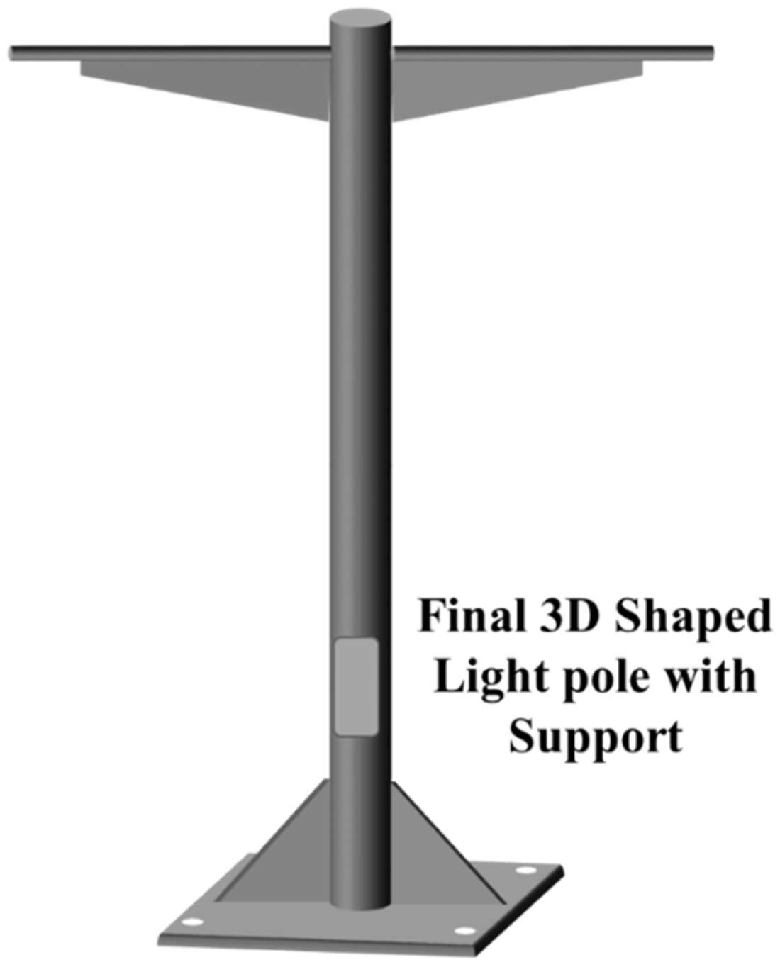
Proposed knitting techniques permit the knitting of single piece of complex shapes using regular flat-knitting machines. As described earlier, steel light pole is made of three main parts, namely anchor base, pole shaft, and brackets/arm which carry the light source. All parts are assembled together via welding process. In this study, flat-knitting machine is used to knit a complete one single preform that contains all light pole parts, whereas all light pole parts are connected together during the knitting process; therefore, no further machining or welding process is required. Figure 3 illustrates the concept design of the proposed light pole design to be knitted on the flat-knitting machine. Figure 4 illustrates the schematic diagram of the final 3D-shaped knitted light pole preform. Knitting process of the complex 3D-shaped light pole is described as follows.
Anchor base is knitted as two layers knit fabric whereas the bottom part and the two sides are not connected (Figure 3). Pole anchor base supports are two triangles that provide a support to the pole shaft. These supports are one layer knitted fabric. Pole shaft is knitted as a tubular fabric connected to the anchor base and to the two triangle supports (right and left to the light pole). Bracket/arm is the part that carry the light source. This light pole design has two brackets/arms located on both sides of the light pole. Bracket/arm consists of two parts, bottom part (triangle shape) is designed to provide extra support to the bracket/arm. The top part is a tubular fabric and it holds the light source. The main target of this tubular section is to provide path for electric wire to pass through. Schematic diagram of the final 3D-shaped knitted preform.
Development of complex 3D-shaped flat-knitting preforms
For the creation of such complex 3D shapes, the innovative knitting techniques using minimum of two yarn feeders were used. Small scale of light pole preform was fabricated with total of 140 needles per needle bed. One hundred needles per needle bed are used to knit the anchor base and 140 needles per needle bed are used to knit the top wide part of the preform, which contains the brackets/arms on both sides of the light pole shaft. The following knitting procedures are shown in Figure 5.
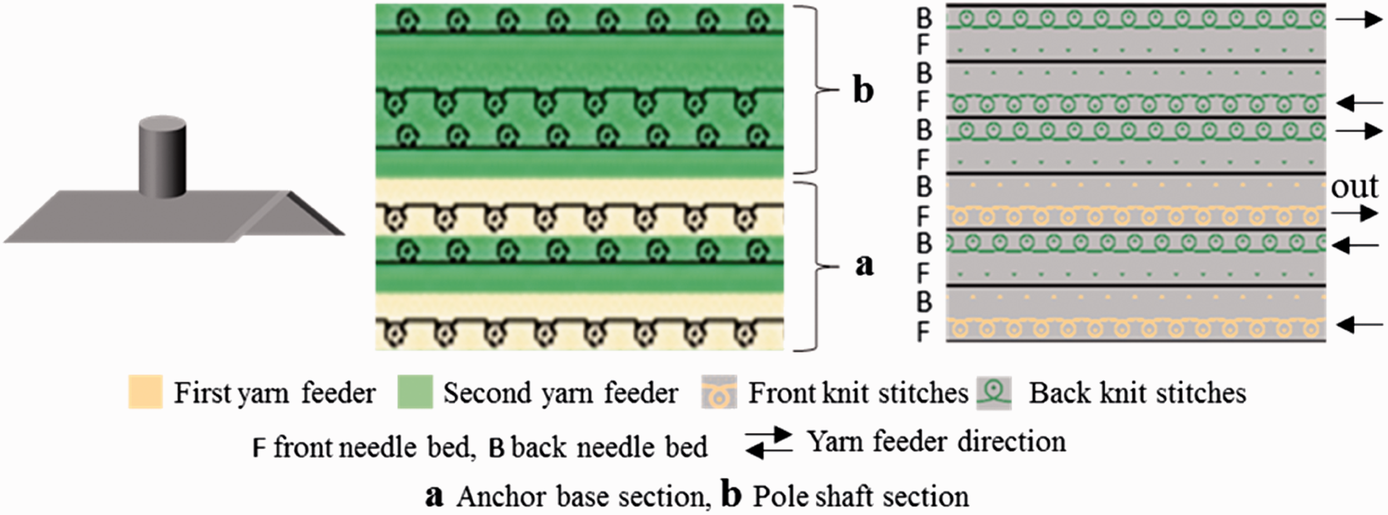
As described earlier, anchor base is a two-layer fabric that is connected from one side (top part which is attached to the bottom section of the pole shaft) and not connected from bottom and both sides. So, in order to knit the anchor base with this specification, two yarn feeders are used. One yarn feeder (first yarn feeder) is used to knit the top layer of the anchor base and it works on needles located on the front needles’ bed, the other yarn feeder (second yarn feeder) is used to knit the bottom layer and it works on back needles which are located on the back needle bed. This technique will permit the production of two separate layers and not connected from both sides and bottom part as well. Knitting cycle is repeated until the determined length is reached. Front and back knit stitches are shown in ivory and green colors in Figure 5. Pole shaft is a tubular structure that is linked from both sides, so only one yarn feeder will be used to knit the tubular structure (second yarn feeder which is indicated in green color). The first yarn feeder used previously to knit the back of the anchor base will move out of the fabric section. Figure 6 shows the schematic diagram, knitting symbol, and technical notation of the anchor base and pole shaft connection. It can be seen from the technical notation that after the determined length of the anchor base is knitted (section Two diagonal supports are designed to provide support to the light pole shaft. These two supports are linked to the pole shaft and the anchor base (Figure 7). Same yarn feeder used to knit the light pole shaft is used to knit the two supports. In order to knit this part of the light pole preform, in each knitting cycle the yarn feeder works on needles located on front bed and back bed at the same time. This knitting structure will provide higher yarn density and thicker fabric. Total of 17 needles per needle beds are used, this number of needles presents only half of the needle density on both needle beds which are used to knit this part of the preform. To give the supports the triangle shape (Figure 8), knit stitches must decrease gradually to the left over a number of courses. This technique is called stitch transfer, whereas the stiches are gradually transferred from one needle to the next needle whether right or left. This technique gives clean sealed edges. In this case, the number of stitches decreased to the left from 34 stitches to zero stitches in 71 courses. The transferred techniques occurred in several steps as follows and technical notation is shown in Figure 8.
Back stitch is transferred from back needle to front needle; One knitting cycle is performed; Front stitch is transferred from the front needle to the back needle; Back needle bed is moved to the left; Then back stich is transferred from back needle to the second front needle to the left.
Schematic diagram of anchor base (left), knitting symbol (middle), and technical notation (right). Schematic diagram of anchor base and pole shaft connection (left), knitting symbol (middle), and technical notation (right). Schematic diagram of anchor base and pole shaft support (left), knitting symbol (middle), and technical notation (right). Schematic diagram of anchor base and pole shaft right diagonal support (left), knitting symbol (middle), and technical notation (right). Bracket/Arm is the part that carries the light source. Design of bracket/arm includes bottom support and horizontal tubular structure. The main reason of the tubular structure is to conceal the electric cable that transfers the electricity to the light source. Figure 9 shows the schematic diagram of the bracket/arm, knitting symbol, and technical notation. Second yarn feeder which is used to knit the pole shaft is used to knit the bracket/arm support. Half of the needles on both front and back needles beds are used to knit the bracket/arm support to prevent any buckling that may have happened if all needles are used. Working needles are alternated per each cycle to give more rigid and steady structure. In order to knit the bracket/arm, the first yarn feeder which is moved out earlier (after finishing the anchor base section) is moved back to knit the tubular bracket/arm. Two yarn feeders are used in this part to have an open side which will provide a path for the electric wire. The last part of knitting process is the cast off. The main reason of this part is to get the preform out of the machine with clean and sealed edges to prevent any unraveling that may have occurred to the preform during handling. Casting off is similar to stitch transfer, whereas the stiches decrease gradually without knitting any courses after the transferring action (Figure 10). Schematic diagram of pole bracket/arm (left), knitting symbol (middle), and technical notation (right). Schematic diagram of pole bracket/arm castoff (left), knitting symbol (middle), and technical notation (right).
Thus, the number of active needles is decreased by one needle to the left. Repeating transfer action will result on reducing number of needles from 34 to zero in 71 knitting cycle (courses).


Result and discussion
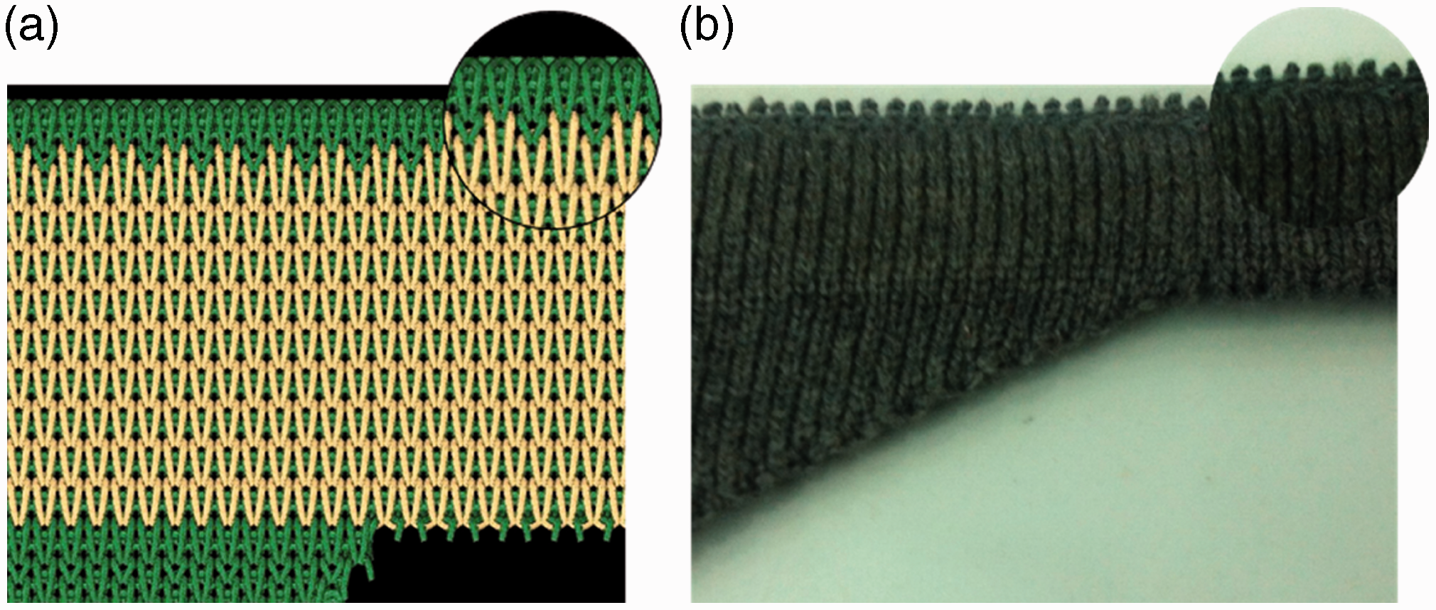
Stoll CMS 430.6 knitting machine with machine gage of 5 needles/in. (2 needles/cm) per needle bed was used to manufacture the light pole-knitted preform. Figure 11 shows flat-knitted innovative-shaped light pole preform. Figure 11 shows the machine final preform right after knitting process. No cut or sewing was carried out on the manufactured knitted preform. Unfolded and folded anchor base are shown in Figure 11(a) and (b). Figures dimensions do not represent the real dimension of the light pole. Final preform consists of 2.7 stitches/cm in the width direction and 5 courses (stitches’ raw)/cm in the longitudinal direction. Preform loop length is 16 mm and dimensions can be controlled by changing the loop length, number of active needle, loop structure, and yarn count. The complex 3D-shaped flat-knitting light pole preform shown in Figure 12 proves that the new knitting technique concepts are extremely flexible in shaping the complex shapes that are suitable for composite applications. Tubular pole shaft is designed to 7.6 cm in diameter and 41 cm in length. Tubular bracket/arms are 1.3 cm in diameter and 21 cm in width. Plastic tubes are inserted into the pole shaft and brackets/arm to give the final shape of the preform. The developed solution for 3D complex-shaped knitted preform offers the chance for significant knitting preforms’ shapes and designs.
Final shaped flat-knitting light pole preform. Final complex 3D-shaped flat-knitting light pole preform.

Figures 13 to 17 show the CAD design, 2D, and 3D images for the complex 3D-shaped preform. Anchor base structure is shown in Figure 13; two different colors (ivory and green) are used in the CAD design to differentiate between the front stitches and back stitches. Each color was driven by separate yarn feeder to acquire an unconnected side and bottom as shown in Figure 13(b). Full needle density of 2 needles/cm per needle bed is used to knit the anchor base preform. Figure 13(c) shows the final shape of the unfolded square shape anchor base with dimension of 36 cm × 36 cm. Pole shaft–anchor base support is shown in Figure 14. To provide the two supports with a strong and thicker structure, the two supports are knitted as a one-layer preform, which means needles located on both front bed and back bed are used to knit the two supports. And since the pole shaft and the anchor base are knitted as a two-layer preform and each needle bed is responsible for only one layer, therefore half of the needle density of each needle bed are used to knit the two supports. In this case the same number of needle/cm for both needle beds per knitting cycle was used for anchor base, pole shaft, and pole support (Figure 7). This will prevent any buckling that may occur. Figure 14 shows the clean edges as a result of the stitch transfer technique.
CAD design, 2D, and 3D images of anchor base-knitted preform. CAD design, 2D, and 3D images of pole shaft–anchor base support. CAD design, 2D, and 3D images of pole shaft preform. CAD design, 2D, and 3D images of bracket/arm preform. Bracket/arm flat-knitting preform cast off.


Pole shaft preform is shown in Figure 15. Thirty needles per needle bed are used to knit the 7.5 cm diameter tubular pole shaft preform. One yarn feeder is used to knit the pole shaft preform, while two yarn feeders are used to knit the bracket/arm tubular preform (Figure 16). Bracket/arm is opened from both sides to permit the electric wire to pass through. Figure 17 shows the clean ending of the last stitch raw of bracket/arm after the casting off. This will prevent the last raw to unravel during the future handling during the composite manufacturing.
Figure 18 shows a small scale of final composite structure of the light pole. Plastic tubes were threaded into the tubular section of the pole to acquire the cylindrical shape. The plastic tubes were covered with release agent to facilitate its removal afterword. Hand layup using polyester resin was conducted to fabricate the final shape of the light pole composite. Any other composite fabrication technique such as resin transfer mold, vacuum bagging, and vacuum-assisted resin transfer molding may be used. Cotton yarn was used in this paper to prove the concept of manufacturing a 3D complex shape, as manufacturing a 3D complex shape (such as light pole) using a flat-knitting machine was the main objective of this paper. Other types of yarns can be used such as glass fibers and carbon fibers. It is worth mentioning that final composite’s mechanical properties depend on fibers and matrix types.
Final light pole composite structure.
Nevertheless, this innovative technique can be used to design numerous complex shapes, which is very difficult with other preform fabrication methods, such as different shapes and dimensions of light poles, traffic signal light, traffic signs, and scaffold façade. Knitted composites materials are considered anisotropic due to the nature of yarn orientation in the knitted preforms [25]. Knitted composite is characterized by its impact and delamination resistance; these characterizations are due to the high energy absorption of its loop structure. Moreover, the modulus can be enhanced by adding straight yarns as a reinforcement weather in wale direction or course direction [26]. Several researches were conducted to investigating the mechanical properties of knitted preform composite. Some of these researches studied the effect of knitted fabric structures on composite mechanical properties [27]. Rib 1×1 was found to have the highest breaking load, highest strain, and highest work of rapture of 610.91 N, 17.98 %, and 5.84 N m, respectively. It was also found that loop length and stitch density have a significant effect on knitting composite tensile properties [28]. Ramakrishna and Hull [29] have investigated energy absorption capability of knitted glass/epoxy and knitted carbon/epoxy composite tubes under different impact test speed. Results revealed decrease in specific energy absorption for both materials by 20% in impact loading [30].
Conclusion
FRPs are becoming a preferable substitute to metal due to its light weight, high strength-to-weight ratio, and noncorrosive nature. Metal light poles are made of several parts that are welded together, which consume more time and add more cost to the manufacturing process. There are several techniques for manufacturing FRP poles such as filament winding, pultrusion, and Resin Transfer Molding (RTM). Even these techniques cannot be used to produce a one piece of FRP light pole. Whereas, stacks of fibers or fabrics preforms are tailored to the shape of the light pole parts, then these parts are assembled together to have the final shape of light poles.
In this study, an innovative technique was developed to produce a one-piece FRP light pole without any further cut and sewing process. In this innovative technique, a flat-knitting machine was used to produce a complex 3D-shaped preforms for composite application. The produced light pole knitted preform includes all light pole parts, namely anchor base, pole shaft, anchor base–pole shaft supports, and bracket/arms. Mechanical properties of such complex preform can be determined by yarn type, yarn count, needle density, and loop length. The proposed novel 3D complex knitted shape permits tremendous application possibilities such as light weight complex shape structures, scaffold façade, and traffic signs.
Footnotes
Acknowledgement
The author is thankful to the Egyptian United Group company for using their facility.
Declaration of Conflicting Interests
The author(s) declared no potential conflicts of interest with respect to the research, authorship, and/or publication of this article.
Funding
The author(s) received no financial support for the research, authorship, and/or publication of this article.