
Abstract
Textile-based body worn sensors are preferred due to its comfortability for continuous monitoring of the body vital signs and kinematics. This research discusses the development and characterization of elastomeric tape for strain sensor application and is used for the measurement of elbow angle. The stress strain properties of commercially available elastomeric tapes have been analyzed for the selection of suitable specifications of elastomeric tape. The actual sensor has been developed with the help of narrow width tape loom by introducing the silver-coated nylon yarn in the middle of the tape structure. The effect of linear density of conductive yarn and number and strands of conductive threads used on sensitivity of the sensor was studied. The repeatability of the developed sensor was characterized by cyclic testing using Zwick tensile tester.
Based on the results, polyester yarns were used as base threads along with rubber threads for the sensor development. It was found that sensor developed using finer yarn with six conductive threads has higher sensitivity. The developed sensor was integrated on to elbow sleeve and elbow angle measurement was done. The results of the developed tape sensor have been compared with the hospital goniometer for 10 male subjects. The results showed that the developed tape sensor is suitable for measuring the elbow angles up to 150°.
Introduction
With the rapid development of smart textiles and wearable electronics, textile products have been getting ever more functional and clothing offers new features rather than just protecting against environmental conditions or fulfilling fashion needs. There is ongoing research in the integration of sensing functionality into traditional textile structures and these new textile structures integrated with sensing properties can be defined as intelligent textiles or functional textiles [1, 2]. An improved integration of smart functions into textile structures is especially relevant for the health care sector, where monitoring of body parameters such as respiration, heart activity, blood pressure, and body movement are of particular interest [3]. The integration of electronic properties directly into the clothing environment carries some advantages such as increased comfort, mobility, usability, and aesthetic properties. Electrical functions can be embedded in textiles by using weaving, knitting, and embroidery or nonwoven production techniques. However, one of the main issues that determines the effectiveness of the resulting structure is the selection of an appropriate production method and the incorporation of suitable raw materials to meet such requirements as working range, responsivity, repeatability, and the response time required for the target application [4].
The creation of textile-based strain sensors has attracted researchers’ attention, and hence many investigators are working this area and numerous different kinds of technique have been used in order to create strain-sensing structures [5–7]. Fang et al. developed an electro-elastic dynamic model with surface/interface effect and investigated the electromechanical response of multilayer piezoelectric nano-cylinder under electro-elastic waves [8]. Gheibi et al. fabricated Polyvinylidene fluoride (PVDF) nanofiber mat by electrospinning and showed that the developed mat can be used to convert mechanical energy to electrical power [9]. Sorayani et al. fabricated PVDF–ZnO nanofiber mats by electrospinning technique and analyzed the electrical response of samples based on applied constant mechanical tensions [10]. These sensors are used to measure human body movements or respiratory activity. Scilingo et al. created strain-sensing fabrics by coating Lycra/cotton fabrics with polypyrrole and carbon-loaded rubbers. These strain-sensing fabrics exhibited a strong variation of strain–resistance with time and they showed a high response time to applied mechanical stimulus [11].
Another method for the creation of textile-based strain-sensing structures is embedding of conductive yarns into knitted or woven structures. As a distinction from the coated sensors, they offer an integration of the sensing part during the manufacturing stage of the fabric. Thus, this approach reduces the production stage to one step. Since woven fabrics are generally characterized by their dimensional stability, poor skin contact, and limited elastic recovery, knitted structures are more suitable for strain sensor applications as it is easier to create flexible structures that fit closely against the human body [12]. Zhang et al. created knitted strain sensors by using stainless steel yarns and carbon yarns and identified that the contacting electrical resistance between overlapped fibers is the primary factor in the sensing mechanism. They also considered electrically conductive fabrics as pure resistive network and found a solution for the plain fabric circuit network [13, 14]. Kun et al. modeled 1 × 1 conductive rib fabrics as resistive networks and found a relationship between extension and the equivalent resistance both experimentally and theoretically [15]. Li et al. also investigated the relationship between the electrical resistance and textile force, which includes the length-related resistance of conductive yarns and the contact resistance of two overlapped yarns [16]. However, the effects of base fabric parameters on sensor characteristics were not studied in the earlier research.
The primary objective of this new study was to develop plain woven fabric-based strain sensors using narrow width tape loom by introducing the silver-coated nylon yarn in the middle of the tape structure. The stress strain properties of commercially available elastomeric tapes have been analyzed for the selection of suitable elastomeric tape specifications. Thus, this study enables the creation of more reliable sensors in terms of repeatability. Silver-coated nylon yarn was used as a sensing element and this was introduced in the middle of the tape structure to help reduce the conductive yarn structural deformation during long-term force loading. The following section describes the selection of elastomeric tape specifications based on analysis of stress strain behavior of different elastomeric tapes and production of elastomeric strain sensors followed by the testing method for the sensitivity of the developed tape sensors. The third part reports the results obtained from the experimental procedure and discussion of the electromechanical properties of the developed sensor.
Materials and methods
Materials used
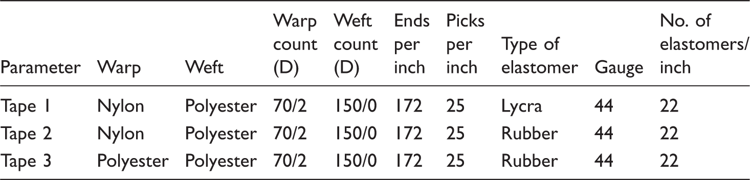
Sourced tape specifications.
Methods
The sourced tapes were tested in Zwick/Roell tensile tester to measure the cyclic load-bearing capacity. The test was carried out three times with 40% extension and 50 cycles each with a preload of 0.5 N with 250 mm as gauge length at a traversing speed of 250 mm/min. The sensor has been developed with the help of narrow width tape loom by introducing the silver-coated nylon yarn in the middle of the tape structure.
Resistance and gauge factor measurement
The elastomeric tape sensors were extended with the help of fabric extension meter from an initial length of 25 cm. They were extended up to 40% with an interval of 1 cm. The resistance change (linear resistance) thus caused due to the extension was noted down using Agilent 34401A 6½ digital multimeter. The gauge factor was calculated by using the formula given below

Strain-sensing mechanism
The tape structures are woven in a tensioned state which when relaxed makes the warp yarn, except the rubber yarns, to shrink and form a loop-like structure. Because of the compact woven structures, the loops of conductive yarn thus formed touch each other.
According to Holm’s contact theory

From equation (2), it can be seen that the electrical resistivity and material hardness are constant for a given material, but the number of contact points and the contact pressure are variable depending on the sensor design [17]. Thus, higher contact pressure and increased number of contact points between conductive parts lower the contact resistance (idle condition of the tape sensor). When the tapes extend (during the force loading), the contact points between the loops gradually decrease and hence there is an increase in the path of the current flow. The increase in the path of the current flow increases the resistance of the conductive yarn, so the overall electrical resistance of the tape sensor.
Results and discussion
Analysis of tensile characteristics of elastomeric tapes
Force required for 40% extension.

The cyclic loading test was carried out for three times with 40% extension and 50 cycles each and hysteresis curves of the tapes are shown in Figure 1. It is observed that the tape 3 shows the consistent increase in stress for the extension and the curve merge as one showing its good recovery potential.
Displacement vs. force graph for 50 cycles (a) Tape 1, (b) Tape 2, and (c) Tape 3.
The area of hysteresis for the first 50 cycles for all the tapes is shown in Figure 2. It can be clearly seen from the graph that the area of hysteresis goes on decreasing with the increase in the number of loading and unloading cycle. From the results of tensile testing graphs, it is observed and confirmed that the conditioning cycles are necessary for the tapes before the measurements in order to increase the accuracy and repeatability. Table 3 shows the coefficient of variation of hysteresis and it is observed that the reduction in the Coefficicent of variation (CV%) is very high in tape 3 i.e. CV% is only 2.09 after 50 cycles.
Area of hysteresis for first 50 cycles. Cyclic loading results.

Analysis of change of stress for unit change of extension
From the cyclic testing results, the displacement Vs force curve for the mid (25th) cycle has been separated out and the slope of the loading and unloading curve has been calculated in order to find out the change of stress for unit change of extension.
Figure 3 shows the change of stress for unit change of extension for the above three tapes. It is observed that the loading and unloading curve follows the same trend in case of tape 2 and tape 3. The change of stress for unit change of extension is very high at lower degrees of stretching and hence it was assumed that the change in resistance will also be high at lower degrees of stretching. However, among tape 2 and tape 3, considering the low force taken by the tapes (7.9 N for tape 2 and 6.8 N for tape 3) and low CV% in hysteresis (2.73% for tape 2 and 2.09% for tape 3) and the change of stress for a unit extension, the specifications of the tape 3 were considered to be suitable for a strain sensor development.
Change of stress for unit change of extension (a) Tape 1, (b) Tape 2, and (c) Tape 3.
Effect of linear density of conductive yarn on gauge factor
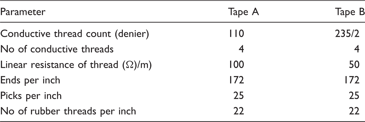
Specifications of Tape A and Tape B.
Resistance vs. extension of sample tapes A and B.


Displacement vs. resistance of tapes A and B.
It is clearly observed from Figure 4 that the resistance goes on increasing with the increase in stretch up to some point and then there is a small drop in resistance, again there is an increase and a drop in resistance. The same trend is observed in both the cases. The increase in resistance in the starting may be due to the increase in length due to extension of crimp and the drop in resistance is because of the high stretch, the crimp is removed and all the yarns will combine and act as a single yarn, which reduces the resistance. The trend is observed to be very minimal in case of Tape-B due to the lower resistance and the coarser yarn structure, which restricts the change in resistance and it is the reason for the lower gauge factor of Tape-B.
Effect of number of conductive threads and yarn strand on gauge factor
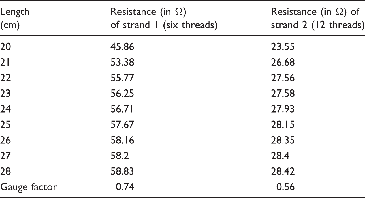
In order to study the influence of number of conductive threads and the yarn strand on the tape sensor sensitivity, tapes have been produced by replacing the base threads with conductive threads in one and two dents, respectively (Figure 5) and the gauge factor has been calculated by stretching the 20 cm tape to 40% extension. For measurement of resistance, all the conductive threads were combined and the overall resistance has been considered and the results are shown in Table 6. It is observed that the tapes with two strands of conductive threads have a lower gauge factor than that of the single strands. It is due to the rubber threads that separate the two sets of conductive threads and thus these two strands will act as resistors in a parallel circuit, so the resultant resistance will be lower than that of the actual resistance present in a circuit. So the gauge factor is lower for the tape developed using 12 conductive threads.
Tapes with two different yarns strand. Influence of yarn strand on gauge factor.
Sensitivity of the textile strain sensor
The final tape sensor has been developed with six conductive threads (single strand) of 110 dtex in a plain weave pattern. Hysteresis is the most important parameter and it should be low for good sensitivity. So in order to study the hysteresis behavior of the developed elastomeric tape sensor, it was subjected to cyclic loading for 25 cycles using Zwick/Roell tensile tester and Figure 6 shows the elongation and recovery behavior of the elastomeric tape for 25 cycles.
Displacement vs. force graph of final tape sensor for 25 cycles.
The area of hysteresis of the developed elastomeric tape for 25 cycles is shown in Figure 7. A peculiar behavior was observed that the hysteresis of initial four cycles deviated from other cycles. After the first four cycles, the area of hysteresis is almost constant and confirming the repeatability of the tape. Table 7 shows influence of first four cycles on the average area of hysteresis, standard deviation (SD) and CV% of hysteresis values. It is observed that CV% of the area of hysteresis for 25 cycles is 13.08. But the CV% of hysteresis excluding the first four cycles i.e. 5–25 cycles is only 3.07. From this, it was confirmed that the conditioning cycles are necessary for the elastomeric tape before taking actual measurements in order to increase the accuracy and repeatability. Hence, it was decided that to give first four cycles as preconditioning before actual testing for reducing hysteresis effect of elastomeric tape. So it was programmed in the software of the tester to give four preconditioning cycles before the actual measurement to improve the sensitivity of strain sensor.
Area of hysteresis of the final tape sensor for 25 cycles. Hysteresis properties of tape sensor.

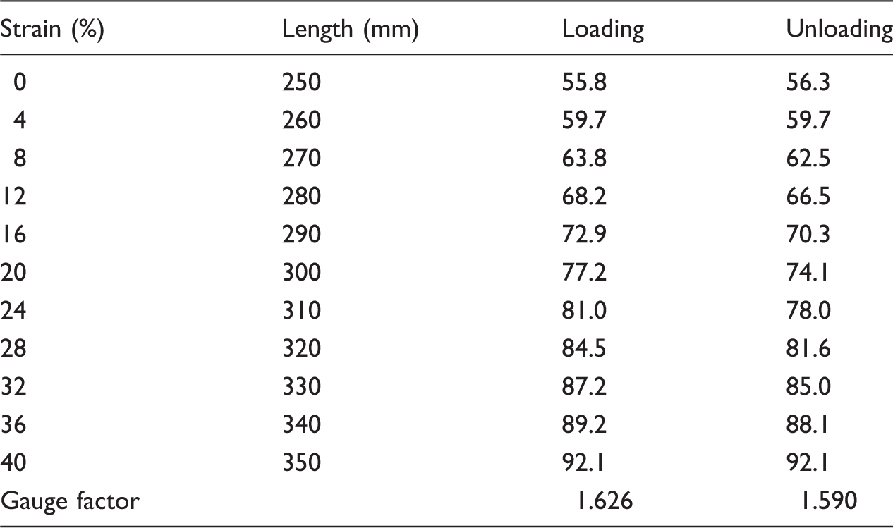
Change in resistance for change in strain of the final tape sensor.
Gauge factor for five cycles for final tape sensor.


Repeatability trends of five cycles of final tape sensor.
Measurement of elbow angle using textile strain sensor
In order to measure the elbow angle using the developed tape sensor, the sensor has been integrated with the elbow sleeve as shown in Figure 9. The angle calibration has been done with the help of mechanical goniometer and measurements were done for 10 subjects and the trial is repeated for five times for each subject [14]. Figure 10 shows the average result of all the subjects. It is clear from the results that the repeatability of the tape sensor is good because all the bending and relaxation curves overlap with each other. CV% has been calculated for all the subjects in order to find out the variability within the subject readings. Some of the samples exhibited the CV% above 1, it is due to the change in initial resistance of the sample, which changes the rate of change. This may be due to time delay at the time of measuring the resistance, which makes the tape to relax itself and changes the rate of change in resistance and increases the CV% within the subjects. The results from all the subjects were averaged out in order to get a single bending and relaxation curve and is shown in Figure 11.
Sensor-integrated elbow sleeve. Elbow angle vs. change in resistance for 10 subjects. Elbow angle vs. change in resistance (average of 10 subjects).


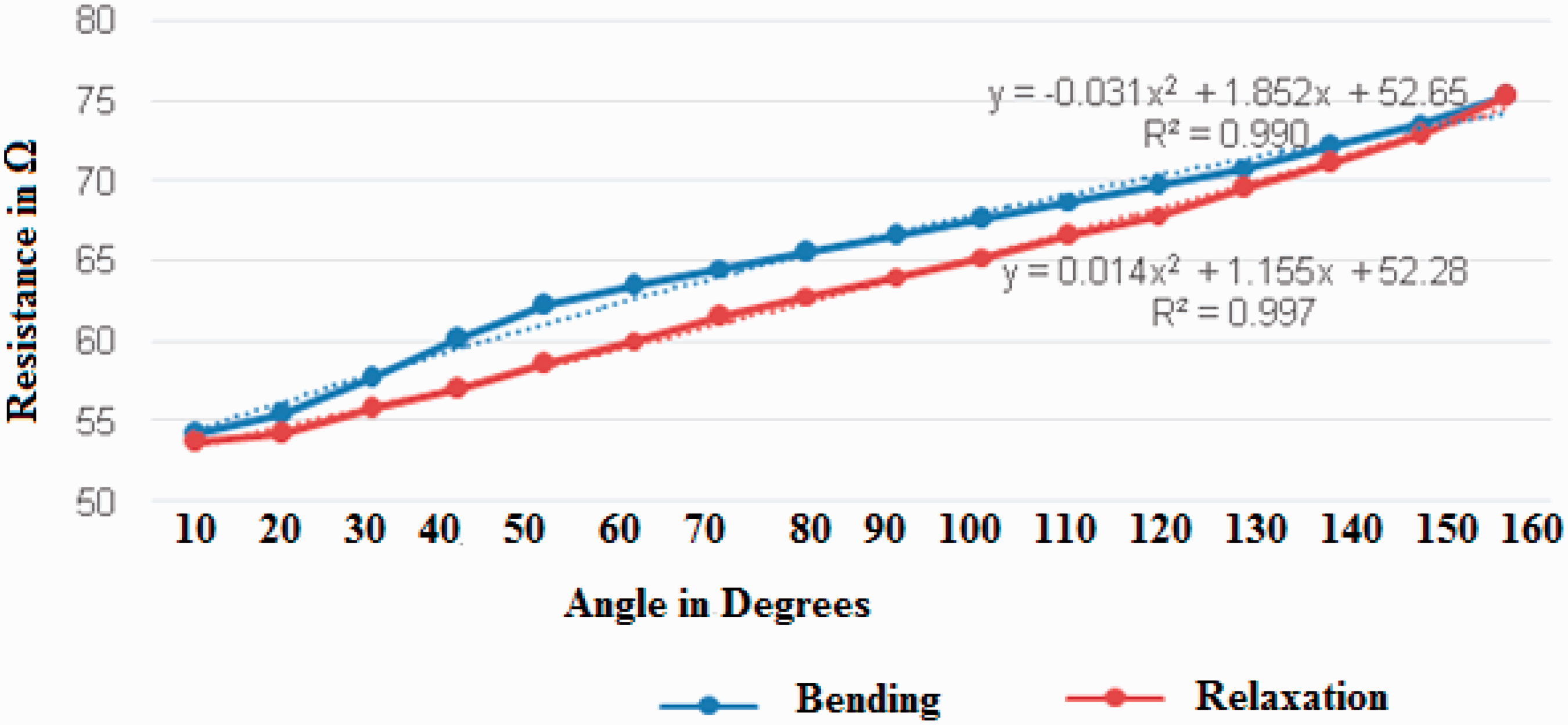
From the averaged bending and relaxation curves, quadratic equations (3) and (4) have been derived. Equation (3) shows the relationship between the resistance changes for the bending cycle and the elbow angle. The equation has R2 value of 0.9908 that indicate that the derived equation follows the reality with 0.92% error. Equation (4) shows the relationship between the resistance changes during the relaxation cycle and the elbow angle. The derived equation has R2 value of 0.9977. It is clear that the chance for equation (3) to fail from the reality is 0.33%. These R2 values are above 0.85, so these equations can be programmed to give the elbow angle at the time of bending and relaxation. From these results, it is concluded that the developed tape sensor can be used to measure the elbow angle up to 150°.
Conclusions
In this work, tensile characteristics of the commercially available elastomeric tapes were analyzed using Zwick/Roell tensile tester in order to optimize the specifications for the textile strain sensor. It was found that the elastomeric tapes made from polyester yarns with 22 rubber threads per inch take less force and have lower CV% in hysteresis during cyclic tensile testing and hence these specifications were used for elastomeric tape strain sensor development. The sensor made from 110 dtex with six conductive threads has good sensitivity.
From cyclic testing results, it is concluded that preconditioning of the elastomeric tape sensor reduces the hysteresis effect thus increasing the repeatability and also increases the sensor sensitivity. The developed textile sensor has been tested for change in resistance with linear extension for strain sensor application and it is observed that there are changes up to 40% extension. The elastomeric tape sensor so prepared can be used to measure the elbow angle up to 150°.
Footnotes
Declaration of Conflicting Interests
The author(s) declared no potential conflicts of interest with respect to the research, authorship, and/or publication of this article.
Funding
The author(s) received no financial support for the research, authorship, and/or publication of this article.